
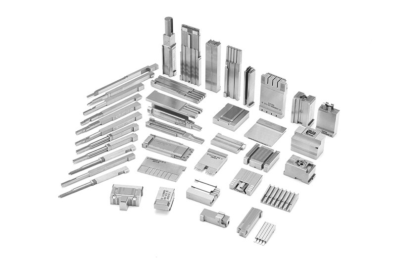
Plastic film parts · Precision mold insert
Board to Board, FPC, RF Mold Parts – Precision Connector Components for RF & Signal Applications Board to board, FPC,RF mold parts
Brand Xuxiang Mold
Availability Made to drawing
RFQ pricing
Quote from STEP / PDF & quantity
Engineer reliable high‑frequency connections with these precision Board to board, FPC, RF mold parts designed for demanding PCB and flexible circuit assemblies. Each molded RF component is optimized for stable impedance control, consistent contact pressure, and secure mechanical retention in compact electronic designs. Ideal for RF modules, antenna boards, test fixtures, and miniaturized devices, they help you reduce signal loss and improve long‑term reliability. Combine them with your preferred board‑to‑board and FPC connector systems to streamline layout, simplify assembly, and increase production yield.
(Board to board, FPC,RF mold parts)
- ISO 9001:2015–oriented process & documented inspection paths
- Zeiss / Nikon class metrology available for critical dimensions
- DFM feedback from 10+ senior tooling engineers
- Dongguan HQ + Quanzhou capacity for volume programs
Board to board, FPC,RF mold parts
High‑Precision Board to Board, FPC, RF Mold Parts for Advanced PCB Integration
These Board to board, FPC, RF mold parts are specialized connector and housing components engineered for modern RF and high‑speed signal designs. They support robust interconnections between rigid PCBs, flexible printed circuits (FPC), and RF modules while maintaining tight mechanical tolerances and consistent electrical performance.
As devices get thinner and more complex, engineers increasingly rely on compact board‑to‑board and FPC connectors to route RF and high‑speed signals in constrained spaces.[3][9][14] Our RF mold parts are designed to complement these connector systems, providing precision‑molded dielectric structures, shielding interfaces, alignment features, and strain‑relief support that help maintain signal integrity and mechanical reliability through the entire product life cycle.
Whether you are building wireless communication modules, IoT sensors, automotive electronics, industrial control units, or consumer devices, these RF mold parts give you a robust foundation for dense interconnect architectures and repeatable mass production.
Key Features & Benefits
Engineered around industry best practices for board‑to‑board and FPC interconnects, these RF mold parts offer a practical combination of mechanical strength and RF performance.[2][3][9][14]
- Optimized for Board‑to‑Board and FPC Connections
Designed to interface with common fine‑pitch board‑to‑board and FPC/FFC connectors, enabling short RF paths and compact module stacking.[2][3][5] - RF‑Conscious Mold Design
Dielectric geometry and clearances are arranged to support controlled impedance routing, minimize parasitic capacitance, and reduce reflections in RF circuits. This is especially beneficial around antenna feeds, RF front ends, and filter networks.[1][12] - Stable Mechanical Retention
Locating posts, alignment ribs, and molded support walls reduce connector stress during mating/unmating, vibration, and drop events. This helps maintain contact normal force and prevents micro‑cracking on solder joints over time.[7][9] - Support for Fine‑Pitch, High‑Density Layouts
Compatible with microminiature connector footprints and narrow‑pitch FPC terminations, allowing designers to stack boards or fold FPCs in extremely tight enclosures without sacrificing reliability.[2][6][15] - Versatile RF and Signal Use
Suitable for low‑power RF modules (Wi‑Fi, Bluetooth, GNSS), intermediate‑frequency routing, and sensitive analog or mixed‑signal sections where controlled routing and shielding are essential.[1][12] - Manufacturing‑Friendly
Geometry is optimized for automated assembly with pick‑and‑place, reflow, and standard SMT lines. Clear mechanical registration features help reduce placement errors and improve yield.[5][8] - Durability in Demanding Environments
When paired with appropriate connector families and PCB materials, these mold parts support applications in automotive, industrial, and telecom products that see temperature cycling, vibration, and long service lives.[4][7][14]
Specifications & Key Attributes
The table below summarizes typical attributes of Board to board, FPC, RF mold parts. Exact values vary by specific part number, connector system, and application; use this as a selection guide during design and sourcing.
| Attribute | Description |
|---|---|
| Product type | Precision‑molded RF connector parts for board‑to‑board and FPC interconnects |
| Compatible interconnect styles | Board‑to‑board mezzanine connectors, board‑to‑FPC / FFC connectors, RF module interfaces |
| Typical pitch compatibility | Fine‑pitch connectors commonly used in high‑density PCB and FPC layouts (exact pitch per series) |
| Supported PCB types | Rigid FR‑4 boards, rigid‑flex boards, and flexible printed circuits (FPC)[9][10] |
| Typical applications | RF modules, wireless communication boards, IoT devices, automotive electronics, industrial control, consumer electronics |
| Material class | High‑performance insulating and structural polymers suitable for RF and SMT processing (specific resin per part) |
| Mechanical features | Alignment bosses, guide walls, strain‑relief supports, seating planes tailored to selected connector families |
| Electrical focus | Support for controlled impedance routing, minimized parasitics, and stable RF performance when used with proper PCB design |
| Assembly method | Surface‑mount or through‑hole locator options, compatible with automated pick‑and‑place and reflow processes |
| Design customization | Custom geometry and interface features can be developed to match specific connector, FPC, or RF layout requirements |
Typical Use Cases & Ideal Users
Board to board, FPC, RF mold parts are well‑suited for a wide range of electronics manufacturers and design teams who need compact, reliable RF interconnections.
- RF Module Integration
Use these mold parts to mount and align RF daughterboards on a main logic PCB, ensuring repeatable spacing and reliable shielding around RF front‑end components such as LNAs, PAs, and filters.[1][12] - Antenna and FPC Routing
For devices where the antenna resides on a flexible circuit or separate board, mold parts can guide and support the FPC path, protecting it from kinking and maintaining stable impedance at transition points.[9][10][13] - Compact Consumer Devices
Smartphones, wearables, handheld terminals, and home automation products often rely on fine‑pitch board‑to‑board and FPC connectors for space‑saving stack‑ups. RF mold parts help achieve consistent assembly quality across high‑volume builds.[2][3][6] - Automotive & Industrial Electronics
In ECUs, telematics modules, ADAS sensors, and industrial controllers, stable RF connections must survive temperature cycling and vibration. Properly designed mold parts work with automotive‑grade connectors to enhance long‑term durability.[4][7][14] - Test, Measurement & Prototyping
Engineers can use these parts to create modular RF evaluation boards, test fixtures, or interchangeable RF front‑end blocks that plug into a common baseboard, speeding up iteration and validation.
Design & Buying Guidance
To get the best performance from Board to board, FPC, RF mold parts, consider the entire interconnect system, not just the individual component.[2][3][9][14]
- Match Parts to Your Connector System
Start by selecting your board‑to‑board or FPC connector series and pitch, then choose mold parts whose geometry and seating planes are compatible. This minimizes tolerance stack‑up and ensures proper mating alignment. - Consider RF Path and Impedance
Plan RF transmission lines (microstrip or stripline) and ground reference planes around the mold geometry. Maintain controlled impedance at transitions, avoid unnecessary stubs, and keep RF paths as short and direct as possible.[1][12] - Account for Assembly Processes
Verify that the parts are suitable for your soldering process (typically reflow) and that pick‑and‑place equipment can recognize and handle the mold geometry. Provide clear fiducials and keep‑out zones on the PCB.[5][8] - Environmental & Compliance Requirements
For automotive or industrial deployments, confirm material suitability for operating temperature range, flammability rating, and any required industry standards through the specific part documentation.[4][7] - Prototype Before Volume
Build initial prototypes with the selected board‑to‑board/FPC connectors and RF mold parts together. Verify mechanical fit, insertion/extraction forces, and RF performance under realistic test conditions before committing to mass production.
By treating these mold parts as an integral part of the RF and connector system, you can improve both product robustness and manufacturing efficiency.
FAQ
Are these Board to board, FPC, RF mold parts compatible with my existing connector series?
Compatibility depends on the specific connector family, pitch, and board layout you are using. In most cases, these mold parts are intended to complement common fine‑pitch board‑to‑board and FPC connector types. Share your connector part numbers and PCB drawings with your supplier to confirm mechanical fit and alignment before ordering for production.[2][3][15]
Can I use these mold parts in high‑temperature or automotive environments?
Many board‑to‑FPC and RF interconnect solutions are designed for elevated temperatures and automotive conditions, but exact limits vary by part.[4][7] Always review the material specifications and operating temperature ranges for the particular mold part and connector combination to ensure they meet your application requirements.
How should I design my PCB to maintain RF performance around these parts?
Use controlled‑impedance transmission lines, maintain a continuous reference ground plane, and keep RF traces as short and direct as possible near the mold interface.[1][12] Avoid sharp bends and sudden width changes, and consult your RF and connector datasheets for recommended pad layouts and ground stitching practices.
Do these Board to board, FPC, RF mold parts affect assembly or rework?
They are generally compatible with standard SMT assembly lines, including pick‑and‑place and reflow processes.[5][8] For rework, follow recommended procedures for your FPC or board‑to‑board connectors, using appropriate temperature profiles and tools to avoid damaging nearby RF components.
What is the typical lead time and shipping method for these RF mold parts?
Lead time depends on whether you are ordering standard or customized parts and on current inventory levels. Smaller quantities typically ship by standard courier, while volume production orders may use scheduled logistics. Check with your distributor or manufacturer for up‑to‑date lead times and shipping options.
Can I request custom geometry or private‑label RF mold parts?
Custom designs are often available for OEM customers who need specific interface heights, alignment features, or enclosure integrations. Provide your mechanical models, PCB stack‑up, and RF requirements so the engineering team can evaluate feasibility and tooling details.
How do I ensure proper fit when stacking multiple boards with these parts?
Use accurate 3D models of the mold parts and associated connectors in your CAD tool to validate clearances, stack heights, and tolerance accumulation. It is recommended to build pilot assemblies and perform mechanical stress tests before full‑scale production.
What is the warranty and returns policy for Board to board, FPC, RF mold parts?
Warranty terms vary by supplier but typically cover manufacturing defects for a defined period. Inspect incoming parts for visual or dimensional issues before assembly. If you encounter defects, document the issue with photos and lot numbers and contact your supplier for RMA and replacement or credit handling.
How should I store these RF mold parts before assembly?
Keep parts in their original packaging to protect them from dust, mechanical damage, and moisture. Store in a dry environment within the recommended temperature and humidity range for electronic components, and observe any moisture‑sensitivity labeling if provided.
Do I need any special cleaning or maintenance after assembly?
Once assembled, these mold parts typically require no special maintenance beyond standard PCB handling practices. Avoid aggressive chemical cleaners that could attack plastic materials, and follow your connector manufacturer’s guidelines if periodic inspection or cleaning of the mating contacts is required.
Same drawing, predictable results—next batch
Share revision, quantity ramp, and inspection level. We quote process route, ship date, and documentation in one structured response.