
Plastic film parts · Precision mold insert
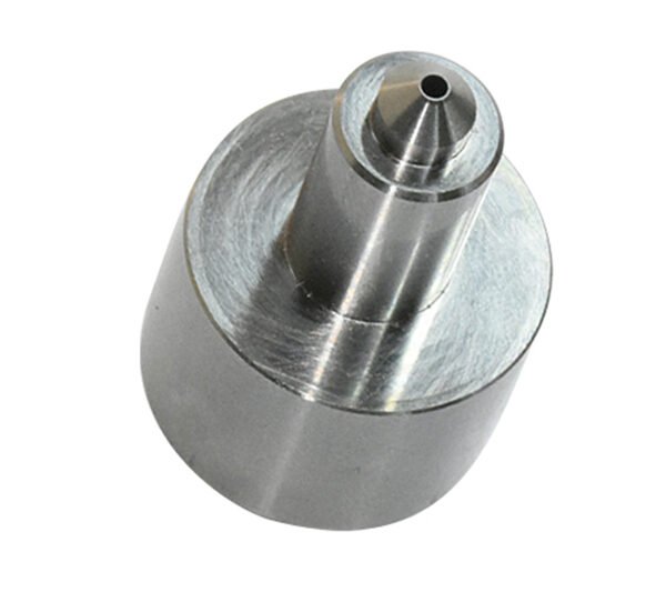
Board to Board, FPC, RF Mold Parts – Precision RF Connector Components Board to board, FPC,RF mold parts
Brand Xuxiang Mold
Availability Made to drawing
RFQ pricing
Quote from STEP / PDF & quantity
Enhance the reliability of your RF and high-speed designs with precision-engineered board to board, FPC, RF mold parts. Built for modern compact electronics, these components support stable signal integrity between PCBs and flexible printed circuits in demanding environments. Robust molding and tight-tolerance metal inserts help reduce noise, improve mechanical stability, and extend product life cycles. Ideal for RF modules, IoT devices, and compact communication systems, they integrate seamlessly into automated SMT and assembly lines. Choose these parts to simplify your RF connector architecture while maintaining high performance and production efficiency.
(Board to board, FPC,RF mold parts)
- ISO 9001:2015–oriented process & documented inspection paths
- Zeiss / Nikon class metrology available for critical dimensions
- DFM feedback from 10+ senior tooling engineers
- Dongguan HQ + Quanzhou capacity for volume programs
Board to board, FPC,RF mold parts
What Are Board to Board, FPC, RF Mold Parts?
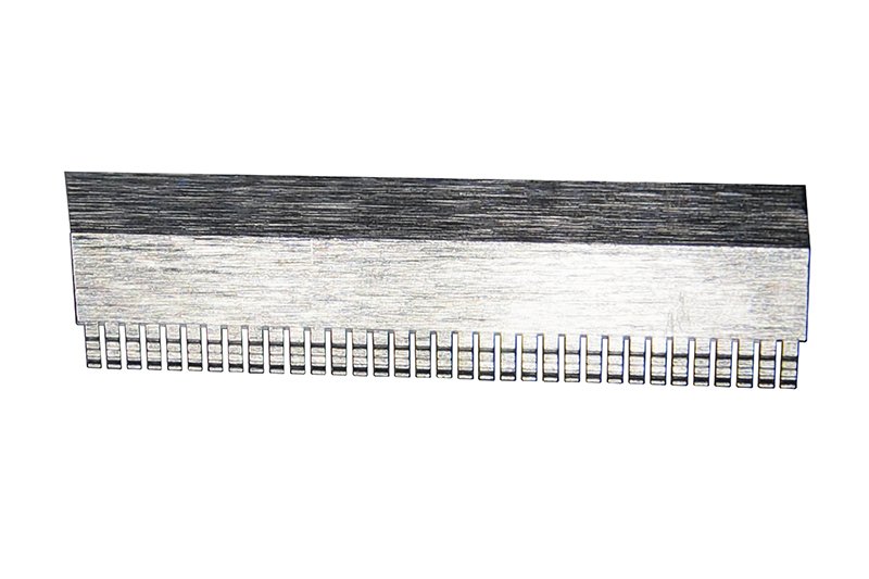
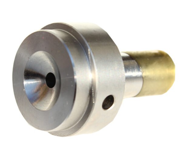
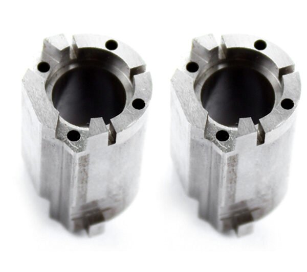
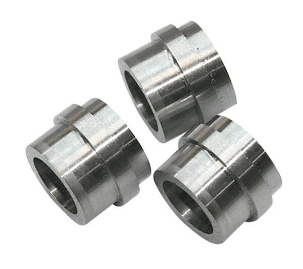
Board to board, FPC, RF mold parts are specialized mechanical and electrical components used inside RF connectors and RF modules to create robust connections between rigid printed circuit boards (PCBs) and flexible printed circuits (FPCs). They typically include precision metal terminals, shielding elements, alignment features, and encapsulating molded housings designed to maintain consistent impedance and signal integrity for radio-frequency applications.
In many RF systems, designers must route sensitive signals across multiple boards or from a rigid PCB to a flexible tail that interfaces with antennas, displays, or sensors. Board-to-board and FPC connectors, supported by dedicated RF mold parts, provide a compact and reliable way to achieve this without bulky cabling or hand-soldered jumpers. These parts are used in applications such as wireless modules, routers, base stations, IoT devices, automotive telematics, industrial radios, and consumer electronics.
By combining precise metal contacts with high-performance molding materials, this family of components helps protect RF paths from mechanical stress, vibration, and environmental influences while making assembly easier and more repeatable on modern production lines.
Key Features & Benefits
Board to board, FPC, RF mold parts are engineered with RF performance, manufacturability, and durability in mind. When specified correctly, they offer multiple advantages for OEMs and design engineers.
- Stable RF performance: Carefully controlled contact geometry and dielectric materials help support consistent impedance and low insertion loss along the signal path, which is critical for RF, microwave, and high-speed digital lines.
- Reliable board-to-board and FPC transitions: Components are designed to bridge gaps between parallel or stacked PCBs, as well as between rigid boards and flexible circuits, reducing the need for coaxial jumpers or discrete wiring.
- Compact, high-density layouts: Fine-pitch contact arrangements allow more signals to be routed in a small footprint, supporting today’s miniaturized wireless modules, wearables, and handheld devices.
- Mechanical robustness: Molded housings and reinforcement features protect contacts from vibration, shock, and repeated mating cycles, extending product life in harsh environments such as automotive or industrial applications.
- Improved assembly efficiency: Parts are typically designed for automated pick-and-place handling and reflow processes, reducing manual operations and improving yield.
- Design flexibility: A combination of vertical and horizontal orientations, multiple pin counts, and different stacking heights or FPC insertion directions helps match mechanical constraints and enclosure designs.
- Enhanced shielding options: Mold parts can integrate or support metal shields, ground structures, and reference planes to minimize EMI/EMC issues and crosstalk between adjacent signals.
Specifications & Core Attributes
The exact characteristics of board to board, FPC, RF mold parts vary by series and manufacturer. Instead of fixed values, the following table outlines the key attributes you should evaluate when selecting components for your design.
| Attribute | Description |
|---|---|
| Connection type | Board-to-board, board-to-FPC, or FPC-to-board RF interconnect structures for internal signal routing. |
| Typical applications | RF modules, wireless IoT devices, automotive telematics units, industrial radios, base stations, routers, consumer electronics. |
| Mating orientation | Vertical (stacking) or horizontal (coplanar) board-to-board arrangements; top or bottom contact for FPC configurations. |
| Pitch / density | Fine-pitch and high-density layouts designed for compact RF circuits and multi-signal connectors. |
| Contact design | Spring contacts or stamped terminals optimized for RF signal integrity and reliable contact pressure. |
| Insulator / molding material | High-performance plastics selected for dimensional stability, dielectric properties, and thermal resistance. |
| Shielding options | Support for integrated metal shields, ground frames, or surrounding structures to reduce EMI and crosstalk. |
| Operating environment | Designed for use in standard or harsh environments, depending on series, such as automotive, industrial, or outdoor systems. |
| Assembly method | Typically compatible with automated pick-and-place and reflow soldering; FPC insertion may use flip-lock or slide-lock mechanisms. |
| Compliance & quality | Offered by manufacturers with industry-quality processes; check individual series for specific standards and test data. |
Use Cases & Who They Are For
Board to board, FPC, RF mold parts are suited for a wide spectrum of RF and high-speed electronics where space, performance, and reliability are equally critical. They serve as underlying components in complete connector systems or custom RF modules.
- OEMs designing RF modules: Ideal for Wi‑Fi, Bluetooth, cellular, GNSS, UWB, and proprietary RF modules that need compact internal interconnects between RF front-end, baseband, and antenna sections.
- Automotive electronics suppliers: Useful in telematics units, ADAS sensors, infotainment systems, and keyless entry modules, where vibration and temperature extremes demand robust molded components.
- Industrial & IoT device makers: Enable modular architectures in gateways, smart meters, asset trackers, and remote monitoring equipment where a combination of rigid and flexible PCBs is required.
- Consumer electronics brands: Support slim layouts in smartphones, tablets, wearables, AR/VR devices, and portable audio where internal board stacking and FPC routing save space.
- Network & infrastructure equipment: Assist in compact RF sections of routers, base stations, small cells, and repeaters that must maintain high reliability over long service lifetimes.
Engineering teams who need consistent RF behavior, easy manufacturability, and long-term mechanical stability can benefit from integrating these components early in the design phase. Mechanical designers, electrical engineers, and manufacturing engineers all have a stake in choosing the right mold parts to support the overall connector system.
Selection & Buying Guidance
Choosing suitable board to board, FPC, RF mold parts for your project starts with understanding your RF performance requirements and mechanical constraints. Use the following points as a checklist during component selection and discussions with your connector supplier or mold-part manufacturer.
- Define the RF bandwidth and signal type: Clarify whether the lines will carry narrowband RF, broadband RF, high-speed digital (e.g. SERDES), or mixed-signal traffic, and make sure the chosen parts support the required performance.
- Determine board spacing and FPC routing: Measure the stacking height between boards, the angle of approach, and the necessary flex routing so that the mold parts and connector structures fit without mechanical interference.
- Consider environmental conditions: Temperature extremes, vibration, shock, humidity, and potential contamination influence the choice of molding materials, plating, and mechanical reinforcement.
- Plan for manufacturing and test: Check that components support your assembly process (SMT, reflow profiles, AOI constraints) and allow easy access for RF test points or fixtures.
- Review lifetime and maintenance expectations: The required number of mating cycles, potential field replacements, or modular upgrades can affect the ideal contact design and housing robustness.
- Collaborate with your supplier: For custom RF mold parts or tailored board-to-board / FPC solutions, early engagement with the manufacturer helps optimize geometry, materials, and tooling for your specific application.
By carefully balancing RF electrical performance with mechanical and manufacturing considerations, you can select board to board, FPC, RF mold parts that support stable operation, cost-effective production, and long-term reliability.
FAQ
Are these board to board, FPC, RF mold parts compatible with my existing RF connector series?
Compatibility depends on the mechanical dimensions, pitch, and contact arrangement of your current connector family. Many mold parts are tailored to specific connector series, so it is important to cross-check drawings and consult your supplier with your existing part numbers to ensure a proper fit.
How should I evaluate RF performance when choosing these components?
When assessing RF performance, review the connector or module data for parameters such as impedance control, insertion loss, return loss, and crosstalk in your operating frequency range. Ask your supplier for available test reports, S‑parameter data, or application notes that describe how the mold parts influence the overall RF path.
What design information do I need to provide for custom RF mold parts?
For custom parts, prepare 3D models or detailed drawings of your PCBs and FPCs, target stacking heights, expected RF frequency bands, and any environmental or regulatory requirements. Sharing early prototypes or evaluation boards can also help the manufacturer optimize the design.
Can these components be used in high-vibration environments such as automotive or industrial systems?
Yes, many board to board, FPC, RF mold parts are specifically designed to withstand vibration and shock. When selecting for harsh environments, prioritize designs with secure locking features, reinforced housings, and test data that demonstrate performance under vibration and thermal cycling.
How are these parts assembled in production?
Most components are supplied in tape-and-reel packaging for automated pick-and-place assembly onto PCBs, followed by reflow soldering. FPC insertion may be a separate manual or semi-automated step, using flip-lock or slide-lock mechanisms, depending on the connector family.
What special care or handling is required before soldering?
As with other SMT components, store the parts in appropriate moisture barrier packaging and follow the recommended floor life and baking guidelines, if provided. Avoid contaminating contact surfaces with oils or dust, and handle reels and trays carefully to prevent bent leads or damaged housings.
Can I rework or replace these RF mold parts on a finished assembly?
Rework is generally possible but should be done carefully using controlled soldering and reflow tools to protect both the part and the PCB. For RF-critical designs, verify performance after rework with appropriate test equipment to ensure that signal integrity has not been compromised.
What warranty or return options are typical for these components?
Warranty and return policies vary by distributor and manufacturer, but most offer coverage for material and manufacturing defects when parts are used within specified limits. Keep purchase records and lot information, and contact your supplier promptly if you encounter quality issues during incoming inspection or production.
How long is the lead time for standard versus custom RF mold parts?
Standard catalog parts often have shorter lead times, depending on stock levels at distributors. Custom RF mold parts require additional time for design, tooling, sampling, and validation, so it is advisable to discuss timelines and minimum order quantities early in your project planning.
Same drawing, predictable results—next batch
Share revision, quantity ramp, and inspection level. We quote process route, ship date, and documentation in one structured response.