
Plastic film parts · Precision mold insert
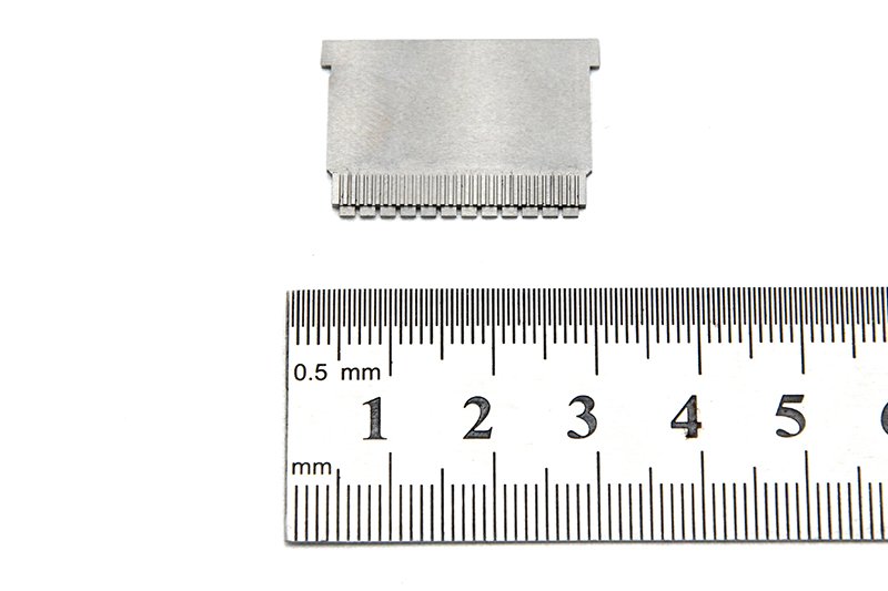
Board to Board, FPC, RF Mold Parts – Precision RF Connector & Molded Component Set Board to board, FPC,RF mold parts
Brand Xuxiang Mold
Availability Made to drawing
RFQ pricing
Quote from STEP / PDF & quantity
Optimize your RF device design with this integrated set of Board to board, FPC, RF mold parts engineered for stable high-frequency performance and reliable mechanical support. Each component is designed to streamline signal routing between PCBs and flexible printed circuits while maintaining excellent contact reliability. The precision RF molding provides consistent dielectric control, shielding and strain relief for demanding environments. Ideal for OEMs, R&D labs and custom module manufacturers, this set helps shorten development cycles and improve long-term product durability. Build compact, high‑density layouts with confidence in both your electrical and mechanical interfaces.
(Board to board, FPC,RF mold parts)
- ISO 9001:2015–oriented process & documented inspection paths
- Zeiss / Nikon class metrology available for critical dimensions
- DFM feedback from 10+ senior tooling engineers
- Dongguan HQ + Quanzhou capacity for volume programs
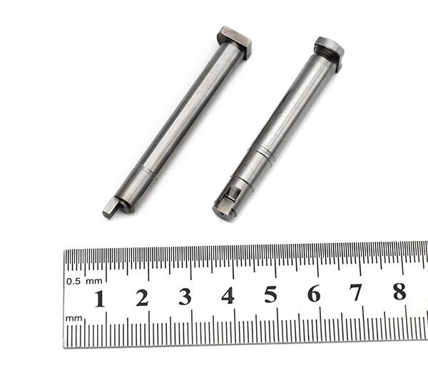
Board to board, FPC,RF mold parts
Overview: What Are Board to Board, FPC, RF Mold Parts?
This product is a precision-engineered set of board to board, FPC, RF mold parts designed for manufacturers and engineers who need reliable interconnections in RF and high-speed electronic assemblies. It brings together three critical elements in one coordinated solution:
- Board-to-board connector interfaces for stacking or edge-to-edge PCB connections.
- FPC (Flexible Printed Circuit) interconnects for tight spaces and dynamic or compact routing between rigid boards.
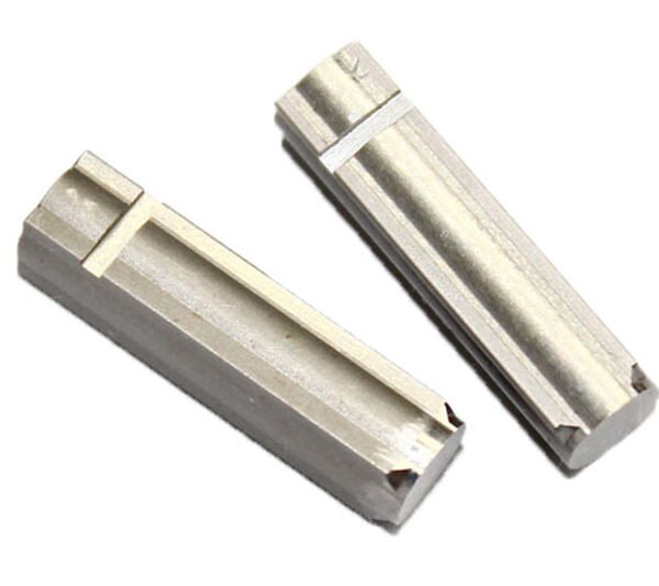
- RF mold parts – custom-molded dielectric and structural components that support RF connectors, antennas, or high-frequency signal paths, adding mechanical protection and signal integrity support.
Instead of sourcing these elements separately, this combined solution is intended for OEM production, custom RF modules, IoT devices, telecom hardware, automotive electronics, instrumentation, and any design where dense packaging and controlled RF performance are essential.
Key Features & Benefits
Every aspect of this set is designed to support professional-grade RF and digital designs, from prototype to mass production.
- Integrated mechanical and electrical design
Board-to-board connectors, FPC interconnects, and RF mold parts are engineered to work together, helping reduce fit-up risk, tolerance stack-up issues, and unexpected signal integrity problems. - Support for compact, high-density layouts
Fine-pitch board-to-board and FPC interfaces allow you to route multiple RF and high-speed signals through minimal board area, enabling thinner, smaller devices without sacrificing performance. - RF-optimized molding
The RF mold parts are designed to provide stable mechanical support and controlled dielectric behavior around the RF path, helping maintain characteristic impedance, reduce parasitic effects, and shield sensitive circuits from external interference. - Enhanced contact reliability
Quality contact structures and retention features help maintain stable connections in environments subject to vibration, thermal cycling, or occasional mechanical stress, which is especially important in automotive, industrial, and portable equipment. - Design flexibility
By combining both PCB-to-PCB and PCB-to-FPC options, the solution gives you freedom to choose rigid stacking, flex bridging, or a hybrid approach as your mechanical constraints and RF layout requirements evolve. - Streamlined sourcing and assembly
Using coordinated board-to-board, FPC, and molded RF parts can simplify your BOM, reduce supplier variation, and make assembly processes more consistent and easier to standardize.
Specifications & Key Attributes
The table below summarizes typical attributes and options associated with this board to board, FPC, RF mold parts solution. Where exact values depend on your selected configuration or custom design, descriptive ranges are used.
| Attribute | Board-to-Board Elements | FPC Interconnect Elements | RF Mold Parts |
|---|---|---|---|
| Typical application | PCB stacking, module-to-mainboard links | Flexible links between rigid boards in tight spaces | Support and housing for RF connectors and traces |
| Pitch options | Fine-pitch suitable for high-density layouts | Fine-pitch FPC interfaces for compact routing | N/A – molded around existing RF geometry |
| Signal type support | High-speed digital and low-loss RF paths | High-speed digital, low-power RF, control lines | Designed for RF and microwave signal regions |
| Mounting style | Surface-mount or through-hole, depending on design | Surface-mount FPC connectors on PCB edge or center | Overmold or insert-mold attached to connector/board |
| Mechanical support | Board stacking height and alignment features | Latch or flip-lock mechanisms to secure FPC | Reinforces connector area and strain relief for cables |
| Environmental resistance | Options for elevated temperature and vibration | Options for repeated flexing and thermal cycling | Resins selected for RF stability and durability |
| Customization | Custom pin counts, orientations, and stacking heights | Custom FPC lengths, orientations, and contact styles | Custom mold geometry, material, and shielding features |
| Industry usage | Telecom, computing, industrial, automotive | Consumer electronics, wearables, IoT, displays | RF front ends, antennas, modules, test fixtures |
Use Cases & Who This Is For
This board to board, FPC, RF mold parts set is particularly suitable for:
- RF module manufacturers integrating amplifiers, filters, antennas, and transceivers into compact boards that require precise mechanical support around RF regions.
- IoT and wireless device designers building gateways, sensors, and handheld products where space is limited and antenna placement is critical.
- Automotive electronics teams creating telematics, ADAS, infotainment, or V2X modules that must withstand temperature variations and vibration while maintaining RF performance.
- Test and measurement equipment builders who need repeatable RF connections between boards and modules inside analyzers, generators, or front-end units.
- Contract manufacturers and EMS providers looking to standardize interconnect solutions, simplify assembly workflows, and reduce rework caused by marginal RF or connector performance.
Typical design scenarios include:
- Stacking a baseband or digital processing board with a separate RF front-end board while keeping RF traces short and well-supported.
- Using FPCs to route RF and high-speed lines around shields, enclosures, or displays where straight-line PCB connections are not possible.
- Encapsulating critical RF components and connectors in custom RF mold parts to improve environmental sealing and reduce electromagnetic interference.
Design, Handling & Buying Guidance
To get the most from this solution, consider the following design and purchasing guidelines:
- Start from your RF layout
Define the RF signal paths, target impedance, and shielding requirements first, then select board-to-board and FPC configurations that preserve short, direct routes. The RF mold part design can be tailored around this layout. - Clarify mechanical constraints
Determine allowable stacking heights, board outlines, bend radii for FPC, and any enclosure limitations. This helps choose connector orientations and FPC entry directions that avoid unnecessary stress. - Plan for assembly and rework
Specify connector types and mold geometries that allow for realistic soldering, inspection, and potential rework in your production environment. Consider the use of alignment features and clear access around solder joints. - Consider environmental conditions
For applications exposed to temperature extremes, moisture, or vibration, select material options and connector versions rated for those conditions. This protects both signal integrity and lifetime reliability. - Engage early on customization
If you require non-standard pin counts, special FPC lengths, or unique RF mold shapes, involve engineering support early in the design cycle to avoid costly revisions late in development.
During procurement, it is helpful to share mechanical drawings, target RF frequencies, and any certification requirements (such as automotive or industrial standards) so that the supplied board to board, FPC, RF mold parts align with your compliance and validation plans.
FAQ
Are these board to board, FPC, RF mold parts compatible with my existing PCBs?
Compatibility depends on your PCB pad layout, pitch, and mechanical stack-up. In most cases, the connectors and mold parts can be matched to your existing design or adapted with minor layout changes. Sharing your Gerber files and board drawings allows an accurate compatibility check.
Can I customize the RF mold part shape and material?
Yes. RF mold parts are typically customized to match your connector type, board outline, and RF performance needs. You can specify geometry, preferred resin families, and any shielding or sealing features so the mold can be tuned to your application.
What should I consider when choosing between board-to-board and FPC links?
If your boards can be aligned and stacked within a fixed distance, board-to-board connectors offer a rigid, compact solution. When boards must move, be offset, or route around mechanical obstacles, FPC links provide flexibility and more freedom in placement. Many designs use a combination of both.
How are these parts shipped and packaged?
Connectors and FPC components are normally supplied in reel, tray, or tape-and-reel packaging suitable for automated assembly, while RF mold parts are provided in protective bulk or tray packaging. For volume orders, packaging can be aligned with your pick-and-place and handling requirements.
Is there a minimum order quantity for custom configurations?
Custom board to board, FPC, and RF mold configurations typically have a minimum order quantity to make tooling and setup economical. The exact quantity depends on the level of customization and project scope, and can be discussed during the quotation process.
How should I handle and solder the FPC connectors?
FPC connectors should be handled with ESD-safe tools and aligned carefully to avoid bending the contacts. Follow your recommended reflow profile and avoid excessive mechanical force during insertion and locking. For rework, use controlled hot air and low-melt solder techniques where appropriate.
What kind of testing is recommended after assembly?
For RF applications, verify return loss, insertion loss, and isolation across your operating band. In addition, perform continuity checks, visual inspection of solder joints, and mechanical stress tests such as vibration or flexing of the FPC where relevant.
What warranty or return options are available?
Standard warranty typically covers material and manufacturing defects for a defined period from delivery. If a part does not meet the agreed specification, it can generally be returned or replaced after evaluation. Details depend on your purchase agreement and local policies.
How should I store unused board to board, FPC, RF mold parts?
Store components in a clean, dry environment at stable room temperature, away from direct sunlight and corrosive atmospheres. Keep connectors and FPCs in their original packaging until use to protect contacts and maintain solderability, and avoid stacking heavy items on top of RF mold parts.
Same drawing, predictable results—next batch
Share revision, quantity ramp, and inspection level. We quote process route, ship date, and documentation in one structured response.