
Plastic film parts · Precision mold insert
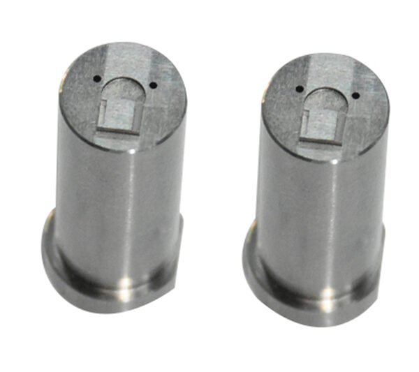
Board to Board, FPC, RF Mold Parts – Precision RF Connector Components Board to board, FPC,RF mold parts
Brand Xuxiang Mold
Availability Made to drawing
RFQ pricing
Quote from STEP / PDF & quantity
Optimize your high-frequency designs with precision-engineered Board to board, FPC, RF mold parts built for modern RF, microwave, and high-speed digital applications. Designed to integrate seamlessly with board‑to‑board and FPC connectors, these molded parts help maintain signal integrity while providing robust mechanical protection. From compact mobile devices to industrial RF modules, they support stable connections in demanding environments. Reduce assembly complexity, improve reliability, and streamline your RF connector design with parts tailored for OEM and custom projects.
(Board to board, FPC,RF mold parts)
- ISO 9001:2015–oriented process & documented inspection paths
- Zeiss / Nikon class metrology available for critical dimensions
- DFM feedback from 10+ senior tooling engineers
- Dongguan HQ + Quanzhou capacity for volume programs
Board to board, FPC,RF mold parts
What Are Board to Board, FPC, RF Mold Parts?
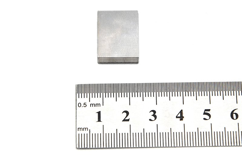
Board to board, FPC, RF mold parts are specialized precision components used around RF and high-speed connectors to provide mechanical support, environmental protection, and stable alignment for signal paths between PCBs and flexible printed circuits (FPC/FFC). They are typically used alongside board‑to‑board mezzanine connectors, board‑to‑FPC connectors, and RF coax or RF board interfaces in devices where both compact size and signal integrity are critical.
In many RF designs, the electrical performance of the connector is only as good as the way it is mounted and protected. Molded parts and associated mechanical pieces help control connector positioning, reduce stress on solder joints, protect delicate FPC tails, and shield RF paths from external impact or contamination. This makes them essential in applications such as wireless modules, IoT devices, automotive electronics, industrial control units, telecom equipment, and consumer handheld products.
Whether you are designing a new RF module or optimizing an existing board stack, incorporating dedicated RF mold parts around your board‑to‑board and FPC connectors can significantly improve long‑term reliability and manufacturability.
Key Features & Benefits
These RF mold parts are engineered to support the mechanical, environmental, and layout needs of high‑density RF boards and FPC assemblies.
- Optimized for board‑to‑board and FPC connectors – Designed to match typical mezzanine and FPC connector footprints used for RF and high‑speed digital signals, allowing clean transitions between PCBs and flex tails.
- Enhanced signal integrity support – By stabilizing connector alignment and reducing micro‑movement under vibration, the mold parts help maintain controlled impedance transitions and minimize reflection or insertion loss caused by mechanical shift.
- Mechanical stress relief – Molded structures provide strain relief for FPCs and PCB pads, reducing the risk of solder joint cracks or pad lifting during drop, shock, or repeated mating cycles.
- Compact, low‑profile design – Suitable for slim products where z‑height and footprint are constrained, such as ultrathin modules, wearable electronics, and compact RF front‑end boards.
- Material options for challenging environments – Mold parts can be produced in engineering plastics suitable for elevated temperatures and industrial or automotive environments, depending on your connector and system requirements.
- Support for automated assembly – Features such as alignment bosses, keying, and pick‑and‑place friendly surfaces help streamline SMT and module assembly processes.
- Customizable geometry – For OEM projects, dimensions and features can be adapted to match specific connector series, board stack heights, or mechanical constraints.
Specifications & Core Attributes
The table below summarizes typical attributes for board to board, FPC, RF mold parts. Exact values and options depend on your chosen connector family and project requirements.
| Attribute | Description |
|---|---|
| Product type | Molded mechanical parts for RF board-to-board and FPC connector support |
| Compatible connector styles | Board-to-board mezzanine, board-to-FPC/FFC, RF module edge, and related RF I/O connectors |
| Typical applications | RF modules, IoT devices, telecom boards, automotive control units, industrial equipment, consumer electronics |
| Material | Engineering thermoplastic or similar material selected for mechanical strength and thermal stability |
| Color | Standard neutral/technical colors; custom colors available on request for orientation coding |
| Thermal performance | Suitable for use near connectors rated for elevated operating temperatures; exact rating depends on chosen material |
| Mounting method | Designed to interface with PCB holes, pads, or connector housing features for secure positioning |
| Mechanical functions | Alignment, strain relief, reinforcement around connector area, protection for FPC tails or RF transitions |
| Customization options | Geometry, height, openings, and mounting features can be adapted to your board layout and connector series |
| Compliance & standards | Designed to support use in systems following common industry and safety requirements; specific certifications depend on project |
Typical Use Cases & Applications
Board to board, FPC, RF mold parts are widely used anywhere that RF and high‑speed digital signals need to cross between PCBs or flex circuits while remaining robust under real‑world conditions.
- Wireless and RF modules – Support RF connectors and FPC links in Wi‑Fi, LTE/5G, GNSS, and proprietary RF modules, improving resistance to vibration and handling during assembly and installation.
- IoT and wearable devices – Help reinforce miniature board‑to‑board and FPC connectors in compact housings, where mechanical shock, bending, and frequent handling can put stress on RF connections.
- Automotive and transportation electronics – Protect connectors and FPCs in telematics units, ADAS modules, and infotainment systems operating in elevated temperatures and under continuous vibration.
- Industrial control and measurement – Provide robust connector support in PLCs, RF measurement boards, industrial gateways, and sensor hubs subjected to harsh operating environments.
- Telecom and networking equipment – Assist with board‑to‑board RF links and FPC jumpers in base stations, small cells, and high‑density networking cards, where consistent RF performance over time is critical.
- Consumer and handheld electronics – Reinforce RF connectors in smartphones, tablets, cameras, audio devices, and portable instruments during drop events and day‑to‑day use.
Buying Guidance & Integration Tips
Selecting the right mold parts for your board‑to‑board and FPC RF connectors involves considering both electrical and mechanical aspects of your design.
- Confirm connector series and pitch – Start from the exact connector part numbers (board‑to‑board or FPC) used in your design and ensure the mold part geometry is compatible with their footprint and stacking height.
- Review mechanical stack‑up – Verify that the mold part supports your target board‑to‑board spacing, enclosure clearance, and any FPC bend radius requirements.
- Check environmental requirements – For automotive, industrial, or outdoor installations, confirm that the material and structure are suitable for your temperature, vibration, and humidity conditions.
- Allow for manufacturing tolerances – Ensure that the design incorporates adequate tolerance for PCB fabrication, connector placement, and molding accuracy, to avoid assembly stress.
- Plan for assembly and rework – Choose designs that are compatible with your assembly sequence and allow reasonable access for inspection and potential rework of the underlying connector.
- Consider customization early – For high‑volume OEM projects, engaging early on custom mold tooling can yield a better mechanical fit, easier assembly, and cleaner RF performance than using generic mechanical supports.
FAQ
Are these board to board, FPC, RF mold parts compatible with my existing connectors?
Compatibility depends on the exact connector series, pitch, and board stack‑up used in your design. In most cases, parts are matched to common board‑to‑board and FPC connector families, and custom options can be developed to fit specific footprints and heights. Providing connector drawings or part numbers helps ensure a correct match.
How do I choose the right size and geometry for my application?
Start by reviewing your PCB layout, connector dimensions, and mechanical stack‑up, including enclosure constraints. From there, select or specify mold parts that align with the connector housing, support the FPC or RF transition, and fit within your height and clearance limits. Mechanical CAD exchange is recommended for final validation.
Can these RF mold parts handle automotive or industrial temperatures and vibration?
Yes, many designs can be produced from engineering plastics and structures suitable for elevated temperatures and continuous vibration. For automotive or industrial projects, share your target operating range so the material and design can be aligned with those conditions.
Will using mold parts affect RF performance?
When properly designed, mold parts support RF performance by stabilizing the connector, reducing micro‑movement, and protecting critical transitions. They are positioned to avoid disturbing the controlled impedance paths while improving long‑term stability of insertion loss and return loss.
How are these parts assembled with my PCB and FPC connectors?
Assembly methods depend on the specific design. Typically, the connector is soldered to the PCB, and the mold part is then placed to engage with board holes or connector housing features. Many designs are compatible with automated pick‑and‑place and standard reflow or post‑reflow mechanical assembly steps.
What kind of maintenance or inspection do these parts require?
The mold parts themselves are generally maintenance‑free. During routine device inspection, verify that the connectors remain fully seated, the FPC is properly inserted and latched, and there is no visible cracking or deformation of the molded supports after mechanical stress or temperature cycling.
Can I request custom colors or markings for orientation?
Yes, custom colors and simple molded‑in markings are often available for volume projects. These help with assembly orientation, revision identification, and visual quality checks during production.
What is the typical lead time and shipping process?
Lead times vary with quantity and whether the part is standard or custom. Standard configurations generally ship faster, while custom designs require tooling and validation. Shipping options include standard and expedited services; packaging is designed to protect precision surfaces during transport.
What is the warranty or return policy for these mold parts?
Warranty coverage typically includes material and manufacturing defects within a defined period. For returns, items should be unused and in original packaging, subject to inspection. For custom parts, policies may focus on conformance to approved drawings and samples.
Can I get samples for prototyping before mass production?
Engineering or pilot samples are usually available so you can validate fit, form, and function in your prototype build. Early sampling is recommended to fine‑tune your PCB layout and mechanical stack‑up before committing to mass production.
Same drawing, predictable results—next batch
Share revision, quantity ramp, and inspection level. We quote process route, ship date, and documentation in one structured response.