
Plastic film parts · Precision mold insert
Board to Board, FPC, RF Mold Parts – Precision RF Connector Components Board to board, FPC,RF mold parts
Brand Xuxiang Mold
Availability Made to drawing
RFQ pricing
Quote from STEP / PDF & quantity
Engineered for demanding RF and high-speed digital designs, these precision Board to Board, FPC, RF mold parts provide reliable signal integrity between PCBs and flexible printed circuits. Each molded RF component is produced with tight dimensional control to support stable impedance, low loss and robust mechanical performance. Ideal for compact modules, IoT devices, automotive electronics and RF front‑ends, they help you simplify layouts while reducing assembly steps. Durable materials and refined molding processes ensure long-term performance even under vibration and thermal cycling. Upgrade your next design with Board to Board, FPC, RF mold parts that are ready for mass production.
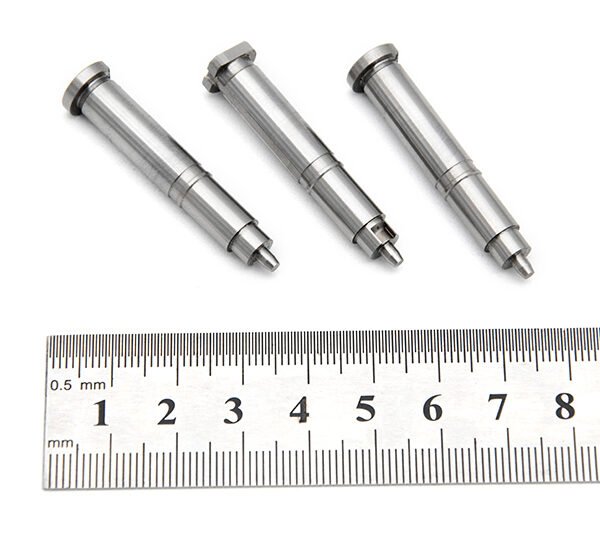
(Board to board, FPC,RF mold parts)
- ISO 9001:2015–oriented process & documented inspection paths
- Zeiss / Nikon class metrology available for critical dimensions
- DFM feedback from 10+ senior tooling engineers
- Dongguan HQ + Quanzhou capacity for volume programs
Board to board, FPC,RF mold parts
High‑Precision Board to Board, FPC, RF Mold Parts for Modern Electronics
These Board to Board, FPC, RF mold parts are specialized precision components designed to support high‑frequency RF and high‑speed digital connections between rigid PCBs and flexible printed circuits (FPC). In compact, space‑constrained designs, they help you integrate antennas, RF front‑ends, cameras, displays and sensor modules without sacrificing electrical performance or mechanical reliability.
By combining optimized molding, carefully selected dielectric materials and connector‑friendly geometries, these RF mold parts provide a stable interface for board‑to‑board and board‑to‑FPC interconnect systems. They are suitable for use alongside industry‑standard FPC connectors, board‑to‑board mezzanine connectors and RF coax / micro‑RF interfaces in applications such as consumer electronics, automotive control units, industrial modules and wireless communication devices.
Key Features & Benefits
Every aspect of these RF mold parts is engineered to support high‑reliability production environments and demanding electrical performance.
- Optimized for RF and high‑speed signals
Designed to help maintain consistent impedance and controlled signal paths, supporting stable RF performance and reduced insertion loss when used with suitable RF connectors and PCB layouts. - Supports board‑to‑board and board‑to‑FPC architectures
Ideal for use in stacked PCB modules, foldable FPC assemblies, hinge areas, and compact RF sub‑modules where space and routing are limited. - Precision molding for tight tolerances
High‑precision mold tooling enables accurate positioning of features such as alignment posts, connector seats, and RF cavities, simplifying assembly and improving repeatability in mass production. - Compatible with FPC and RF connector ecosystems
Designed with geometries that work well with commonly used FPC connectors, board‑to‑board mezzanine connectors and miniature RF interfaces, helping to reduce custom engineering effort. - Mechanical stability and strain relief
The molded structure can provide reinforcement and strain relief in areas where FPCs bend or where RF connectors experience repeated mating, vibration or handling. - Compact, lightweight design
Thin‑wall construction and optimized shapes support high‑density layouts without adding unnecessary weight, important in handheld, wearable and automotive applications. - Production‑ready for automated assembly
Features such as alignment bosses, pick‑and‑place surfaces and clear orientation cues help integrate the parts into SMT or semi‑automatic assembly lines.
Specifications & Key Attributes
The table below summarizes key attributes of the Board to Board, FPC, RF mold parts. Where application‑specific details are required, these can typically be customized or confirmed during the engineering review stage.
| Attribute | Description |
|---|---|
| Product type | Precision RF mold parts for board‑to‑board and board‑to‑FPC assemblies |
| Typical applications | RF modules, antenna units, wireless IoT devices, automotive electronics, industrial control, consumer electronics |
| Supported interconnect styles | Board‑to‑board connectors, FPC/FFC connectors, RF connectors, micro‑coax interfaces (depending on design) |
| Material category | Engineering‑grade insulating molding resin suitable for RF and high‑speed circuitry |
| Mechanical design | Custom‑shaped mold parts with alignment features, connector seating areas and optional strain‑relief structures |
| Operating environment | Intended for use inside enclosed electronic devices; detailed temperature and environmental ratings to be confirmed by project |
| Mounting method | Designed for integration with PCB and FPC assemblies; compatible with adhesive, mechanical fastening or overmolding processes as specified in the project |
| Design customization | Geometry, mounting interfaces and RF cavity layout can typically be tailored to your PCB and connector configuration |
| Compliance & testing | Electrical and mechanical validation can be performed to match your RF, reliability and regulatory requirements |
| Typical industries | Telecommunications, automotive, industrial automation, smart home, consumer electronics, medical monitoring (non‑implant, project‑dependent) |
Typical Use Cases & Applications
These Board to Board, FPC, RF mold parts are used wherever designers need to route RF and high‑speed signals cleanly between rigid and flexible substrates while maintaining mechanical robustness.
- RF front‑end modules
Provide stable mounting and controlled geometry for RF connectors and passive components in front‑end modules for Wi‑Fi, cellular, GNSS or proprietary RF systems. - Antenna integration
Help position and protect FPC antennas or miniature board antennas, improving consistency of RF performance across production batches. - Foldable and hinge areas
Reinforce FPCs where they exit a rigid board or pass through hinge mechanisms, reducing stress concentration and improving long‑term reliability. - Stacked board assemblies
Support board‑to‑board mezzanine connections in compact modules, maintaining proper spacing and alignment for high‑density connectors. - Automotive and industrial controllers
Assist in managing vibration and thermal cycling by providing mechanical support to RF connectors and FPC transitions in ECUs, gateways and sensor nodes. - Wearables and handheld devices
Enable slim, curved or non‑planar layouts where FPCs connect displays, cameras, antennas and sensors to a main logic board.
Selection & Buying Guidance
Choosing the right RF mold parts for board‑to‑board and FPC applications requires a clear understanding of your electrical and mechanical constraints. Consider the following factors when specifying your parts:
- Connector ecosystem
Start with the board‑to‑board, FPC and RF connectors you plan to use, then match mold part geometry to their footprints, heights and mating orientations. - Frequency range and signal type
Define the highest operating frequency and whether the signals are RF, differential high‑speed or low‑speed control. This will guide cavity layout, clearances and potential shielding strategies in the surrounding design. - Mechanical envelope
Review device housing, neighboring components and assembly clearances to ensure that the mold part fits within the mechanical stack‑up and does not interfere with cable bending radii or connector access. - Thermal and environmental conditions
Clarify expected ambient temperatures, potential hot‑spots, vibration levels and any exposure to moisture or contaminants so that material choices and mechanical features can be aligned with your reliability targets. - Assembly process
Decide whether the mold part will be placed manually or by pick‑and‑place, and whether it will be fixed using mechanical features, adhesives or secondary processes such as overmolding. This affects the design of handling surfaces and alignment aids. - Prototyping vs. mass production
During early prototypes, 3D‑printed or small‑batch molded parts may be used to validate geometry and RF behavior. For volume, dedicated high‑precision tooling ensures consistent part quality and lower per‑unit cost.
For best results, involve your mechanical and RF engineers when specifying the final geometry. Providing PCB outlines, connector datasheets and 3D housing models makes it easier to design RF mold parts that perform well electrically and integrate smoothly into your production workflow.
FAQ
Are these Board to Board, FPC, RF mold parts compatible with my existing connectors?
Compatibility depends on the footprint, height and orientation of your board‑to‑board, FPC and RF connectors. In most projects, the mold part is tailored or selected to match the exact connector models used. Sharing connector datasheets and PCB layouts during design review ensures a proper fit.
How do I know if the parts support my RF frequency range?
The usable frequency range is determined by your overall RF design, including connectors, PCB stack‑up and layout. The mold parts are designed not to disturb the intended signal path when used correctly. Your RF engineer should validate performance through simulation and measurement for your target frequency band.
Can these RF mold parts be used in automotive or industrial environments?
Yes, they can be designed for harsh environments when paired with suitable materials and connectors. For automotive and industrial projects, specify your temperature, vibration and lifetime requirements so the parts and validation plan can be aligned accordingly.
What information do you need to help select or design the right parts?
Provide your PCB and FPC outlines, connector part numbers, target frequency range, mechanical stack‑up, environmental requirements and preferred assembly process. This information allows a more accurate recommendation or custom design.
How should I handle and assemble these mold parts on the production line?
Handle the parts with clean gloves or standard ESD‑safe tools to avoid contamination of critical surfaces. During assembly, follow your work instructions for orientation, seating and fixation. Where applicable, use pick‑and‑place nozzles that match the designated handling surfaces on the parts.
Do these parts require any special cleaning or maintenance?
In normal use inside an electronic device, the mold parts do not require maintenance. Before assembly, keep them in clean packaging and avoid exposure to dust, oils or chemicals that could affect adhesion or long‑term stability.
What is the typical lead time for Board to Board, FPC, RF mold parts?
Lead time depends on whether you are ordering an existing design or a custom geometry, as well as current production capacity. Prototyping and first‑article runs usually take longer than repeat orders once tooling is in place.
Can I order small quantities for prototypes before committing to volume production?
Yes, small‑batch or prototype quantities are typically available so you can verify fit, assembly and RF performance before ramping to mass production. Discuss your project schedule so sample and production timelines can be coordinated.
What is the warranty or returns policy for these RF mold parts?
Warranty and returns are generally based on conformance to agreed drawings and specifications. If parts do not meet the documented requirements, they can usually be evaluated for replacement, credit or corrective action according to the supplier’s quality policy.
Do you provide technical support for RF and mechanical integration?
Technical support is typically available to assist with part selection, integration into your board‑to‑board and FPC architecture, and basic guidance on RF and mechanical considerations. Share your design files to receive more targeted recommendations.
Same drawing, predictable results—next batch
Share revision, quantity ramp, and inspection level. We quote process route, ship date, and documentation in one structured response.