
Plastic film parts · Precision mold insert
Board to Board, FPC, RF Mold Parts High-Precision Connector Components Board to board, FPC,RF mold parts
Brand Xuxiang Mold
Availability Made to drawing
RFQ pricing
Quote from STEP / PDF & quantity
Ensure reliable high-frequency performance and compact integration in your next design with these precision-engineered board to board, FPC, RF mold parts. Designed for modern compact electronics, they help you create stable, low-loss signal paths in tight spaces while simplifying assembly. From RF front-end modules to flexible interconnects, these components support robust mechanical retention and excellent electrical continuity. Durable materials and optimized molding structures support demanding environments such as industrial control, IoT devices and consumer electronics. Integrate the KEYWORD into your builds to achieve cleaner layouts, faster production and greater long-term reliability.
(Board to board, FPC,RF mold parts)
- ISO 9001:2015–oriented process & documented inspection paths
- Zeiss / Nikon class metrology available for critical dimensions
- DFM feedback from 10+ senior tooling engineers
- Dongguan HQ + Quanzhou capacity for volume programs
Board to board, FPC,RF mold parts
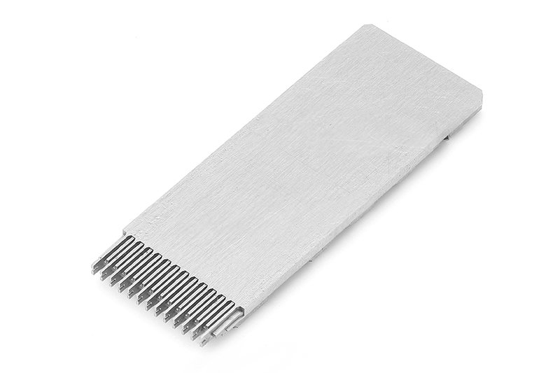
High-Precision Board to Board, FPC, RF Mold Parts for Advanced Electronics
These board to board, FPC, RF mold parts are engineered as critical connector and interface components for modern compact electronic systems. They are designed to bridge printed circuit boards (PCBs), flexible printed circuits (FPCs) and RF circuit sections in a reliable, repeatable and manufacturable way.
In many RF and high-speed applications, designers must route signals between stacked boards, rigid-flex assemblies or RF front-end modules while keeping insertion loss low and mechanical stability high. Board-to-board and FPC connectors, together with dedicated RF mold parts, provide a compact and robust solution for this challenge. These parts help integrate antennas, filters, amplifiers and logic boards into a single, space-saving assembly while maintaining signal integrity.
Typical use cases include wireless modules, IoT gateways, automotive electronics, smart home devices, set-top boxes, routers, base station subsystems, test fixtures and many other applications where RF performance, miniaturization and automated assembly are important.
Key Features & Benefits
Combining connector know-how with high-precision molding technology, these parts are optimized to address both electrical and mechanical requirements of demanding RF and digital designs.
- Versatile interconnect options: Support for rigid board-to-board stacking, board-to-FPC transitions and RF signal routing using molded housings and features that keep alignment tight and consistent.
- Optimized for RF performance: Mold parts and connector geometries are designed to favor controlled impedance paths, short RF runs and stable contact pressure, helping to reduce signal loss and reflections in high-frequency sections.
- Compact, fine-pitch designs: Suited for space-constrained products, with low-profile constructions and narrow pitch options commonly used in portable devices, modules and dense multi-board assemblies.
- Reliable contact and retention: Spring contacts, wiping actions and robust plating on mating surfaces are used in quality FPC and board-to-board connectors to maintain low contact resistance over time, even under vibration or thermal cycling.
- Support for automated assembly: Molded alignment features, pick-and-place compatible shapes and clear polarisation reduce assembly errors and support surface-mount production lines.
- Mechanical protection for RF sections: RF mold parts can encapsulate or shield sensitive RF areas, help manage spacing and improve durability, especially where coaxial lines or microstrip structures transition between boards or FPCs.
- Flexible design integration: The combination of board-to-board, FPC interfaces and RF-specific molding allows designers to create modular architectures that are easier to test, assemble and service.
Specifications & Key Attributes
The exact performance of a given solution will depend on the selected connector series and RF mold design. The table below summarizes typical attributes you should consider when specifying board to board, FPC, RF mold parts for your project.
| Attribute | Description |
|---|---|
| Interconnect Types | Board-to-board mezzanine, board-to-FPC, FPC-to-FPC, RF interface transitions |
| Typical Applications | RF modules, wireless devices, IoT hardware, automotive electronics, communication equipment, consumer electronics |
| Pitch Options | Fine-pitch layouts commonly used in compact electronics; select pitch according to routing density and manufacturing capability |
| Profile Height | Low-profile and mid-profile stack heights to support slim device designs and multi-board stacks |
| Contact Style | Surface-mount contacts with wiping engagement, designed for stable electrical connection and automated soldering |
| Materials | High-temperature, insulating plastic resins for molded parts; copper alloy contacts with conductive plating for reliability |
| RF Considerations | Layouts designed to support controlled impedance traces, minimal loop area, and short RF paths between boards/FPCs |
| Mounting Method | Surface-mount (SMT) compatible components for reflow soldering; some designs may combine SMT with mechanical hold-down features |
| Operating Environment | Suitable for typical commercial and industrial environments; select specialized series for automotive or extended temperature ranges |
| Customization Options | Tailored mold geometries, pin counts, keying and RF shielding structures can be specified for OEM projects |
Use Cases & Who This Is For
These board to board, FPC, RF mold parts are designed for engineers and manufacturers who need reliable interconnect solutions in compact electronics, especially where RF performance matters. They are well-suited to:
- RF and wireless module designers integrating power amplifiers, filters, transceivers and antennas into multi-board or rigid-flex modules.
- IoT device manufacturers building small form-factor gateways, sensors, wearables and trackers where space and performance are both critical.
- Automotive electronics engineers designing infotainment units, telematics modules and driver assistance systems that require robust RF connections and tolerance of harsh conditions (when using appropriately rated series).
- Industrial and communication equipment OEMs producing routers, base stations, test equipment and automation controllers with stacked PCBs and flexible RF interconnects.
- EMS/ODM partners seeking standardized yet adaptable interconnect and mold solutions for multiple customer platforms.
Whether you are updating an existing design or starting a new product, these components help you simplify mechanical architecture, reduce cable harnessing, and provide a cleaner RF layout. The result is a more robust product with less assembly complexity and easier quality control.
Selection & Buying Guidance
Choosing the right combination of board-to-board connectors, FPC interfaces and RF mold parts requires balancing electrical, mechanical and manufacturing constraints. Use the following guidelines as a starting point:
- Define signal requirements: Identify which lines are RF, high-speed digital or low-speed control/power. RF lines may need dedicated paths or shielding features in the mold design.
- Determine board stack-up and spacing: Decide how many boards or FPC layers you need, their relative positions, and the required stack height. This will guide connector orientation (vertical or horizontal) and profile.
- Consider assembly process: Ensure the parts you choose are compatible with your SMT processes, reflow profiles and inspection methods. Look for pick-and-place friendly shapes and clear polarization.
- Evaluate mechanical constraints: Check available footprint area, keep-out zones, and mechanical stresses such as vibration or flexing. Mold parts can add reinforcement or strain relief where needed.
- Review RF performance targets: For sensitive RF designs, coordinate with your RF engineer or layout specialist to place connectors and mold features in locations that minimize discontinuities and preserve impedance.
- Plan for future variants: If you anticipate derivatives with different antennas, bands or board options, choose connector systems that provide some headroom in pin count or stack height, and mold concepts that can be adapted without a complete redesign.
When in doubt, consult engineering support or reference designs that show proven layouts for similar RF and FPC interconnect structures. Physical prototypes and RF simulations can validate that the chosen parts meet your performance and reliability requirements before committing to volume production.
FAQ
Are these board to board, FPC, RF mold parts suitable for high-frequency RF designs?
Yes, they are intended for use in RF and high-speed circuits when selected and laid out correctly. To achieve good performance, ensure that the PCB and FPC traces leading into the connectors and mold structures are designed with controlled impedance and minimal discontinuities. RF-specific mold features can help maintain spacing and shielding around sensitive sections.
How do I check compatibility with my existing PCB and FPC layouts?
Start by reviewing the recommended land patterns, pitch, stack height and orientation of your chosen connector series. Compare these with your current PCB and FPC footprints, mechanical envelope and routing. You may need to adjust pad sizes or board spacing to match. Providing your CAD data to your connector or mold supplier can help confirm compatibility before production.
Can these parts be used in products that experience vibration or mechanical shock?
Many board-to-board and FPC connector systems are designed to tolerate moderate vibration and shock when properly supported. For harsher environments, consider using additional mechanical reinforcement, shorter span FPC runs, or mold features that provide strain relief and prevent undue stress on solder joints.
What should I consider for assembly and soldering?
These components are typically SMT-compatible and intended for reflow soldering. Follow the supplier’s recommended soldering profiles, land patterns and storage conditions. Make sure pick-and-place alignment features are used and that the boards are supported during reflow to avoid warping that could affect joint quality.
How should I handle and maintain FPC connectors during prototyping?
During prototyping, avoid repeated unnecessary insertions and removals of the FPC to reduce wear on contacts. Use proper tools or tabs on the FPC to avoid bending or creasing near the contact area. Keep the connector area clean and free from flux residue or debris that could affect contact reliability.
Do you offer customization for specific RF mold geometries?
Many suppliers can support customized RF mold parts, including tailored geometries, shielding features, keying and mounting points. When requesting customization, share your mechanical models, RF requirements and target production volumes to determine feasibility and lead times.
What is the typical lead time for these components?
Lead times depend on whether you choose standard catalog parts or customized solutions, as well as current production capacity. Standard series are usually available more quickly, while custom molds and assemblies will require additional development and tooling time. It is best to confirm current lead times at the quotation stage.
What are the options if my product requires extended temperature or automotive conditions?
For automotive or extended-temperature applications, select connector families and molding materials that are specified for higher temperature ranges and environmental resistance. Automotive-grade options can provide improved durability, but always verify ratings and test in your specific application.
What is your policy on returns or replacements for these parts?
Return and replacement policies vary by supplier and order type. Generally, unopened standard parts can be returned within an agreed period, subject to inspection, while custom or made-to-order components may have more restrictive conditions. Review the commercial terms and any warranty coverage at the time of purchase.
Same drawing, predictable results—next batch
Share revision, quantity ramp, and inspection level. We quote process route, ship date, and documentation in one structured response.