
Plastic film parts · Precision mold insert
Board to Board, FPC, RF Mold Parts – Precision Connector & RF Structural Components Board to board, FPC,RF mold parts
Brand Xuxiang Mold
Availability Made to drawing
RFQ pricing
Quote from STEP / PDF & quantity
Engineered for demanding electronics, our Board to Board, FPC, RF mold parts deliver stable signal integrity and robust mechanical support in compact assemblies. Precision-molded housings and inserts help you achieve reliable high-density interconnects without sacrificing strength or service life. Ideal for consumer electronics, automotive modules, industrial controllers and RF front-end units, these parts simplify layout, assembly and long‑term maintenance. Partner with us to customize materials, geometry and surface treatment to match your specific connector or RF packaging platform.
(Board to board, FPC,RF mold parts)
- ISO 9001:2015–oriented process & documented inspection paths
- Zeiss / Nikon class metrology available for critical dimensions
- DFM feedback from 10+ senior tooling engineers
- Dongguan HQ + Quanzhou capacity for volume programs
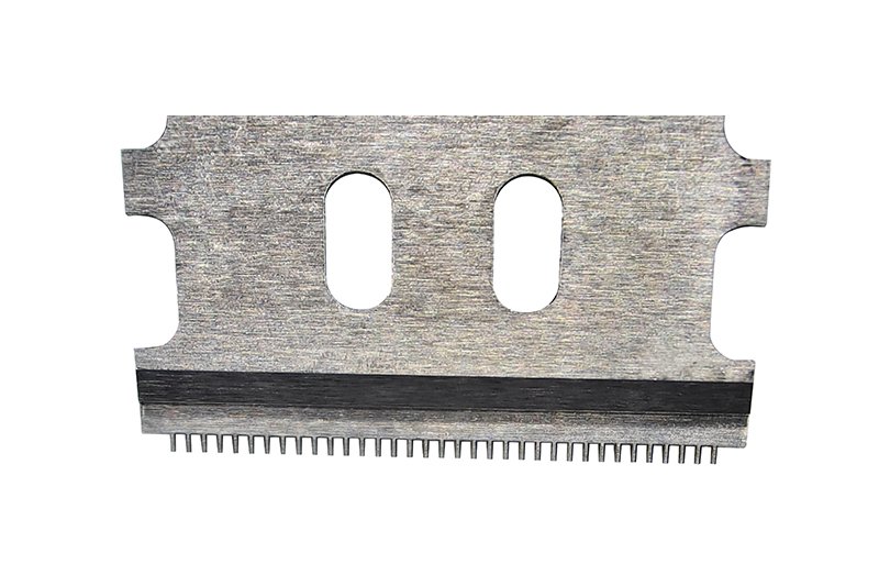
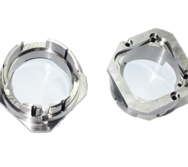
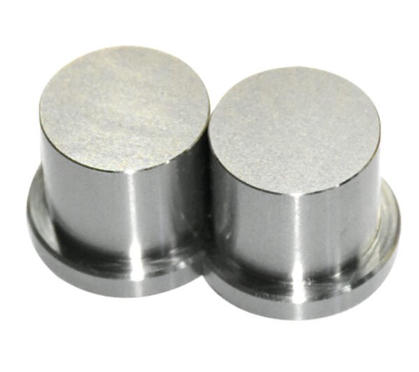
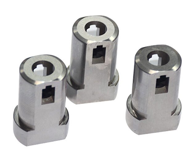
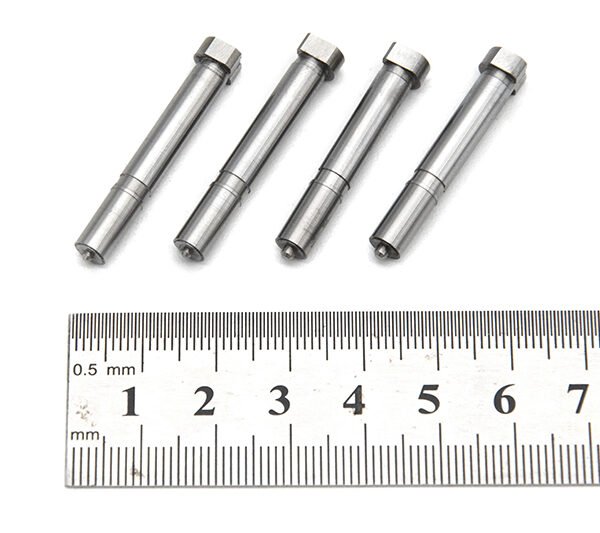
Board to board, FPC,RF mold parts
High-Precision Board to Board, FPC, RF Mold Parts for Modern Electronics
As electronic devices become thinner, faster and more integrated, the mechanical parts that support their connectors and RF circuitry must be just as advanced. Our Board to Board, FPC, RF mold parts are a family of precision-molded components designed to support and protect board‑to‑board connectors, FPC (Flexible Printed Circuit) interfaces and RF structures in a wide range of applications.
These mold parts provide the mechanical backbone for high-density interconnects, helping you maintain alignment, ensure repeatable mating, and shield sensitive RF sections from stress and environmental impact. Whether you are designing compact handheld devices, automotive control units or RF front‑end modules, these parts help convert your electrical design into a reliable, manufacturable hardware platform.
What These Mold Parts Are and How They Fit into Your Design
Board to board and FPC connectors create the electrical bridge between PCBs and flexible circuits, but their performance is only as good as the mechanical structure that holds them in place. The mold parts in this range are engineered plastic and composite components that:
- Position and support board-to-board and FPC connectors in precise alignment.
- Provide strain relief around solder joints, pads and flex tails.
- Integrate guide features, posts and bosses to simplify assembly and mating.
- Form part of RF housings and enclosures to stabilize RF cables, antennas or shields.
- Help manage creepage and clearance distances in mixed-signal designs.
Typical implementations include connector shrouds, housing bases, latch structures, spacer frames, RF bracket molds and overmolded support features for FPC and micro‑RF interfaces.
Key Features & Benefits
Our Board to Board, FPC, RF mold parts are developed to meet the demands of high‑reliability electronics manufacturing. Key advantages include:
- High dimensional precision – Tight mold tolerances help maintain connector alignment and coplanarity, reducing insertion stress and improving long‑term contact reliability.
- Support for fine‑pitch interconnects – Optimized geometries accommodate modern micro‑pitch board-to-board and FPC connectors used in compact consumer and industrial designs.
- Mechanical robustness – Carefully selected engineering resins and design features improve impact resistance and fatigue strength, especially important in mobile and automotive environments.
- Enhanced RF performance – RF‑oriented mold parts can be shaped to support controlled routing, shielding or isolation, contributing to consistent impedance and reduced interference when used with suitable RF connectors and cabling.
- Assembly-friendly design – Built‑in guide ribs, snap features, polarization keys and mounting bosses help reduce assembly errors and shorten production time.
- Compatibility with automated production – Stable part geometries, pick‑and‑place surfaces and clear orientation features support high‑volume SMT and automated assembly lines.
- Customizable material options – Depending on your project, materials can be selected for heat resistance, chemical resistance, flame performance, or low dielectric impact in RF zones.
Specifications & Typical Attributes
Because board-to-board, FPC and RF mold parts are highly application‑specific, exact values vary by design. The table below summarizes the typical attributes and options you can specify when selecting or customizing these components.
| Attribute | Description |
|---|---|
| Product type | Mechanical mold parts for board-to-board, FPC and RF connector support |
| Typical applications | Consumer electronics, automotive electronics, industrial control, telecom, RF modules |
| Supported interfaces | Board-to-board connectors, FPC/FFC connectors, RF connectors and small RF assemblies |
| Material options | Engineering thermoplastics and composites selected for strength, stability and heat resistance |
| Pitch compatibility | Designed to accommodate a range of connector pitches, including fine-pitch signal connectors |
| Mounting style | Through-hole bosses, screw posts, snap-fit features or integration into larger housings |
| Color / marking | Neutral or application‑specific colors; optional molded indicators or orientation marks |
| Thermal behavior | Designed to operate within the temperature range of typical electronic assemblies |
| Environmental resistance | Options for enhanced resistance to vibration, humidity or automotive‑style conditions |
| Customization | Geometry, mounting points, material selection and surface details configurable to project needs |
Use Cases & Who These Parts Are For
Board to Board, FPC, RF mold parts are used by design engineers, manufacturing engineers and procurement teams who need reliable mechanical support for dense interconnects. Typical use cases include:
- Compact consumer devices – Smartphones, tablets, wearables, cameras and handheld instruments use fine‑pitch board‑to‑board and FPC connections that require precise support and strain relief.
- Automotive electronics – ECUs, sensor modules, infotainment units and ADAS controllers benefit from vibration‑resistant mold structures that keep connectors secure under harsh conditions.
- Industrial control and IoT – PLCs, edge controllers and sensor hubs combine rigid and flexible PCBs with RF links where robust mechanical design prevents downtime and field failures.
- Telecom and RF modules – RF front ends, small cells, routers and modems require structural parts that maintain connector integrity and support RF‑critical regions without compromising performance.
- Custom electronic assemblies – Any project that relies on stacked PCBs, folding FPC harnesses or embedded RF sections can benefit from tailored mold components.
Buying Guidance: Selecting the Right Mold Parts
To choose the most suitable Board to Board, FPC, RF mold parts for your project, consider the following guidelines:
- Define connector types and geometry – Start from the footprint, pitch and mating height of your board‑to‑board or FPC connector, along with any RF connector or cable form factor that needs support.
- Evaluate mechanical constraints – Clarify stack‑up height, permissible tolerances, vibration level and insertion / extraction forces to determine required stiffness and support features.
- Account for thermal and environmental conditions – For automotive or industrial environments, specify materials and designs rated for higher temperatures and potential exposure to moisture or contaminants.
- Align with assembly processes – Ensure the mold parts are compatible with your assembly flow, whether manual, semi‑automatic or fully automated, including any cleaning or conformal coating steps.
- Plan for service and rework – If connectors or RF modules may need replacement, incorporate accessible fasteners or release features instead of fully captive structures.
Engage with our team early in the design phase to optimize the mold part geometry around your PCB layout, connector selection and RF routing strategy. This collaborative approach helps reduce last‑minute redesigns and improves overall reliability.
FAQ
Are these Board to Board, FPC, RF mold parts compatible with my existing connectors?
Yes, the mold parts are designed to be compatible with a wide range of standard board-to-board, FPC and RF connector families. During the design stage, we review your connector datasheets and PCB layouts to ensure proper fit, clearance and alignment.
Can I request custom shapes or materials for specific projects?
Custom designs are available. You can specify dimensions, mounting style, special ribs or latches, and preferred material characteristics such as heat resistance or dielectric behavior. Our engineering team will help refine the design for manufacturability.
What information do I need to provide to check compatibility?
To confirm compatibility, share your PCB drawings, connector part numbers, stack‑up height, intended mating directions and environmental requirements. This allows us to propose or validate a mold solution that aligns with your mechanical and electrical design.
How are these mold parts shipped and packaged?
Parts are typically shipped in protective bulk or tray packaging designed to prevent deformation and contamination during transit. For high‑volume production, customized packaging and labeling can be arranged to match your assembly workflow.
Do I need special tools or fixtures for installation?
In most cases, the mold parts are installed using standard assembly tools such as screwdrivers or automated pick‑and‑place equipment. If a design requires a special fixture or pressing tool, we can provide recommendations or fixture concepts to support your line.
How should I care for or handle these parts before assembly?
Store mold parts in their original packaging in a clean, dry environment. Avoid excessive stacking or exposure to high temperatures that could cause warpage. Handle with clean gloves where necessary to keep surfaces free of dust and oils.
What is the typical lead time for production orders?
Lead time depends on whether you select an existing design or a custom solution. Standard configurations usually have shorter lead times, while custom molds require additional time for design, tooling and validation. Your sales contact can provide current estimates based on order quantity.
Is there a warranty or return policy for defective parts?
Yes, shipments are covered by a quality warranty that addresses manufacturing defects. If you encounter issues such as dimensional non‑conformance or visible defects, we will work with you on analysis, replacement or credit according to the agreed terms.
Can these parts be used in high‑temperature applications such as automotive compartments?
High‑temperature capable material options are available for applications such as under‑dash or under‑hood electronics. When submitting your requirements, indicate the target operating temperature so that suitable materials and designs can be recommended.
Do you support small prototype quantities as well as mass production?
Yes, we support both prototype runs and mass production. Early prototypes help verify fit and function before committing to large‑scale tooling and volume orders, reducing overall project risk.
Same drawing, predictable results—next batch
Share revision, quantity ramp, and inspection level. We quote process route, ship date, and documentation in one structured response.