
Plastic film parts · Precision mold insert
Board to Board, FPC, RF Mold Parts – Precision RF Connector Components Board to board, FPC,RF mold parts
Brand Xuxiang Mold
Availability Made to drawing
RFQ pricing
Quote from STEP / PDF & quantity
Optimize your next-generation RF designs with precision-engineered Board to board, FPC, RF mold parts tailored for high-frequency connector assemblies. These components are designed to support reliable board-to-board and FPC transitions in compact RF modules, helping you achieve stable signal integrity in demanding environments. From prototyping to mass production, the consistent mold quality and accurate interfaces simplify assembly and reduce rework. Ideal for RF connector manufacturers, OEMs, and EMS providers looking to streamline RF module production with consistent, ready-to-integrate parts.
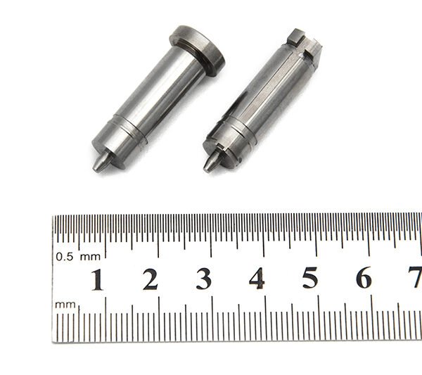
(Board to board, FPC,RF mold parts)
- ISO 9001:2015–oriented process & documented inspection paths
- Zeiss / Nikon class metrology available for critical dimensions
- DFM feedback from 10+ senior tooling engineers
- Dongguan HQ + Quanzhou capacity for volume programs
Board to board, FPC,RF mold parts
Overview: What Are Board to Board, FPC, RF Mold Parts?
Board to board, FPC, RF mold parts are precision-engineered mechanical and insulating components used to form the housing and structural interfaces of RF connectors that link PCB-to-PCB and FPC-to-board signal paths. They are typically custom or semi-custom molded parts that position and protect RF contacts, define connector geometry, and ensure accurate alignment for high-frequency signals.
In modern RF and high-speed digital systems, space is limited yet performance demands keep rising. Board-to-board and FPC connectors must handle tight pitches, controlled impedance, and stringent reliability requirements. Well-designed RF mold parts support these goals by:
- Providing dimensional stability for precise RF contact positioning
- Offering mechanical protection for fine-pitch contacts and FPC tails
- Helping maintain controlled impedance structures within the connector body
- Supporting reliable mating and unmating cycles without damage
These parts are widely used in wireless communication modules, IoT devices, automotive telematics, RF front-end modules, and compact consumer electronics where PCBs, FPCs, and RF signal lines must be interconnected reliably.
Key Features & Benefits
Designed for demanding RF applications, these board to board, FPC, RF mold parts provide a robust foundation for your connector designs.
Precision for High-Frequency Performance
- Accurate molding and tight tolerances support consistent contact positioning, which is critical for impedance control and low signal reflection at RF frequencies.
- Stable dielectric materials help maintain predictable RF behavior and reduce insertion loss in the mated connector system.
- Optimized cavity and wall geometry supports cleaner signal paths and reduced crosstalk between adjacent channels.
Robust Mechanical Protection
- Reinforced housings shield delicate RF contacts and FPC terminations from mechanical stress during handling and assembly.
- Guided mating features minimize the risk of misalignment or stubbing, protecting both plug and receptacle sides.
- Integrated strain relief areas can help reduce stress on solder joints and FPC tails in vibration-prone environments.
Flexible Integration for Board-to-Board and FPC Designs
- Suitable for board-to-board mezzanine connectors, stacking connectors, and edge-mounted RF interfaces.
- Supports FPC-to-board transitions in RF modules where flexible printed circuits must carry signals between rigid PCBs or antennas.
- Can be adapted to different orientations (horizontal, vertical, right-angle) to fit diverse mechanical layouts.
Production-Friendly Design
- Consistent molding quality reduces assembly variation and improves first-pass yield in automated lines.
- Features such as polarization keys, latch windows, and alignment posts simplify connector placement and inspection.
- Compatible with high-volume RF connector manufacturing processes, including overmolding, automated pin insertion, and SMT assembly of finished connectors.
Specifications & Key Attributes
The following table summarizes typical attributes for board to board, FPC, RF mold parts. Exact values and material selections can be tailored to your specific connector design and application requirements.
| Attribute | Description |
|---|---|
| Product type | Molded housings and structural parts for board-to-board, FPC, and RF connector assemblies |
| Typical applications | RF modules, wireless communication devices, IoT terminals, automotive telematics, consumer electronics |
| Supported interconnect styles | Board-to-board mezzanine, FPC-to-board, RF coaxial transitions, mixed-signal RF connectors |
| Pitch compatibility | Designed for fine-pitch RF and FPC connectors; specific pitch depends on the matched connector design |
| Material (housing) | High-performance engineering plastic or RF-grade polymer, chosen for stability and dielectric performance |
| Color options | Standard neutral colors (e.g., natural or black) with optional custom colors for keying and differentiation |
| Operating environment | Suitable for typical electronics environments; high-temperature and automotive-grade options may be available on request |
| Mounting style support | Compatible with connectors designed for SMT, through-hole, or hybrid mounting on PCBs and FPCs |
| Design customization | Custom cavity geometry, keying, latch features, and branding possible for OEM/ODM projects |
| Quality & inspection | Dimensional inspection and visual quality controls aligned with RF connector manufacturing standards |
Use Cases & Who This Is For
Board to board, FPC, RF mold parts are suitable for a wide range of customers across the RF and electronics ecosystem.
RF Connector Manufacturers
- Ideal for companies designing and manufacturing RF board-to-board or FPC connectors who require stable, repeatable molding quality.
- Supports rapid development of new connector families for emerging wireless standards and compact product platforms.
OEMs and Device Designers
- Perfect for OEM engineering teams integrating RF modules into smartphones, tablets, wearables, routers, base stations, industrial gateways, and automotive systems.
- Helps reduce design risk by using proven mold geometry that supports robust RF performance and mechanical reliability.
EMS Providers and Module Houses
- EMS and module manufacturers benefit from consistent fit and alignment when assembling complex RF boards and FPC harnesses.
- Reliable mold parts contribute to smoother SMT and final assembly processes, reducing rework and returns.
Buying Guidance & Customization Tips
Choosing the right board to board, FPC, RF mold parts involves aligning mechanical, electrical, and manufacturing requirements.
- Define your interconnect type: Clarify whether you are building a pure board-to-board connector, an FPC-to-board transition, or a mixed RF/digital mezzanine system. This will determine cavity layout and alignment features.
- Confirm space and stacking height: Evaluate available PCB and enclosure space, including target connector height, insertion direction, and any required keep-out areas around RF transmission lines.
- Consider RF performance targets: Work with your connector or RF engineer to ensure the mold geometry supports your target frequency range, impedance, and isolation requirements.
- Select appropriate materials: If your product will operate in harsh or elevated-temperature environments (such as automotive or industrial), specify materials that can withstand these conditions while maintaining dielectric stability.
- Plan for manufacturing: Include features such as polarization keys, pick-and-place surfaces, and clear visual orientation marks to support automated handling and quality inspection.
- Discuss customization early: For OEM and high-volume projects, engage with the mold and connector supplier early in the design cycle so draft angles, gate locations, and tooling considerations can be optimized.
If you are unsure which configuration is best for your application, share your PCB or FPC layout, target frequency range, and mechanical constraints with the supplier’s engineering team. They can recommend or adapt mold parts that best match your design goals.
FAQ
Are these board to board, FPC, RF mold parts compatible with my existing connector design?
Compatibility depends on your connector’s geometry, pitch, and contact layout. In most cases, mold parts are matched to a specific connector family or customized for an OEM design. Provide drawings or 3D models of your current connector so the supplier can confirm fit or recommend appropriate alternatives.
Can I request custom materials or colors for my RF mold parts?
Yes, many projects use custom materials or colors to meet branding, keying, or environmental requirements. Discuss your target operating temperature, regulatory needs, and visual preferences so material options can be proposed without compromising RF performance.
What information do you need to start a custom mold design?
Typically, you should share:
- PCB and FPC outlines and thickness
- Connector pitch, row count, and mating orientation
- Target frequency range and impedance requirements
- Mechanical constraints such as height and keep-out zones
This information allows the engineering team to design mold parts that align with your RF and mechanical specifications.
How are these RF mold parts shipped and packaged?
Parts are usually packed in protective bags, trays, or reels (for certain geometries) to prevent contamination and mechanical damage during transport. For high-volume programs, packaging can be optimized for automated assembly, such as tray layouts compatible with pick-and-place equipment.
Do I need special handling procedures during assembly?
RF mold parts do not generally require special handling beyond standard ESD and cleanliness practices for electronic components. However, avoid excessive mechanical force or bending, and ensure that any cleaning chemicals used in production are compatible with the selected plastic material.
What is the typical lead time for standard versus custom designs?
Standard or existing designs usually have shorter lead times because tooling is already available. Custom projects require additional time for design validation, tooling fabrication, and first article approval. Confirm current lead times when you request a quotation, as they may vary with production load.
How can I verify quality before mass production?
You can request sample lots or pilot runs to validate fit, function, and RF performance in your own test fixtures. Dimensional reports and inspection records can also be reviewed to confirm that the mold parts meet agreed tolerances.
What is the return or warranty policy on RF mold parts?
Warranty and returns typically cover manufacturing defects in materials or workmanship. If any parts do not meet the agreed specifications, contact customer support with batch numbers, photos, and test results so a replacement or corrective action can be arranged according to the supplier’s quality policy.
Can these mold parts be used in automotive or industrial applications?
Yes, they can be designed for automotive or industrial use when paired with appropriate materials and connector designs. Be sure to state your environmental and reliability requirements, such as temperature range and vibration levels, so the solution can be engineered accordingly.
How do I ensure long-term availability for my project lifecycle?
For long-lifecycle products, it is important to align on lifecycle management and potential tooling maintenance or refresh plans. Discuss forecast volumes and program duration with your supplier so they can plan capacity, tooling support, and any future modifications in a controlled way.
Same drawing, predictable results—next batch
Share revision, quantity ramp, and inspection level. We quote process route, ship date, and documentation in one structured response.