
Plastic film parts · Precision mold insert
Board to Board, FPC, RF Mold Parts High-Precision Connector Components Board to board, FPC,RF mold parts
Brand Xuxiang Mold
Availability Made to drawing
RFQ pricing
Quote from STEP / PDF & quantity
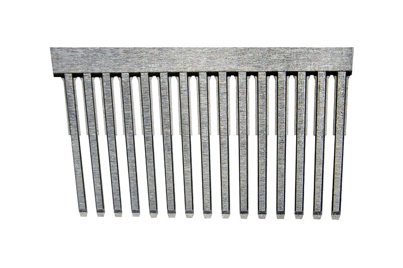
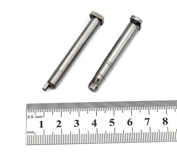
Engineered for modern high-frequency electronics, these board to board, FPC, RF mold parts deliver stable, low-loss signal paths in compact designs. Each molded RF component is produced with tight dimensional control to ensure repeatable impedance and reliable mating in demanding environments. From flexible printed circuit terminations to rigid board stacking, they help you simplify layouts, reduce wiring harnesses, and improve assembly efficiency. Durable materials and optimized RF geometry support long service life under vibration, temperature cycling, and frequent mating cycles. Integrate these parts into your next design to achieve cleaner RF performance and more robust interconnects.
(Board to board, FPC,RF mold parts)
- ISO 9001:2015–oriented process & documented inspection paths
- Zeiss / Nikon class metrology available for critical dimensions
- DFM feedback from 10+ senior tooling engineers
- Dongguan HQ + Quanzhou capacity for volume programs
Board to board, FPC,RF mold parts
High-Precision Board to Board, FPC, RF Mold Parts for Demanding RF Interconnects
Board-to-board (B2B) and FPC (flexible printed circuit) connectors are at the heart of compact, high-density electronic systems, and RF mold parts bring the additional level of control required for stable high-frequency performance. These board to board, FPC, RF mold parts are designed as precision-molded components used within or around RF connector systems to support mechanical stability, signal integrity, and robust environmental performance.
In RF and high-speed digital applications, even small variations in geometry or material can affect impedance and insertion loss. Precision RF molding allows manufacturers to create consistent dielectric structures, shielding features, and connector housings that maintain performance across large production runs. Whether you are integrating FPC jumpers into a compact module or stacking high-speed boards in a tight enclosure, these RF mold parts help deliver reliable interconnects with minimized crosstalk, reflections, and mechanical stress.
Key Features & Benefits
These board to board, FPC, RF mold parts are tailored for OEMs, RF module designers, and contract manufacturers who need dependable, repeatable performance in space‑constrained products.
- Optimized for RF and high-speed signals: Molded dielectric and housing structures are engineered to maintain controlled impedance and reduce discontinuities that can degrade RF or SerDes channels.
- Supports board-to-board and FPC architectures: Suitable for use with stacking board-to-board connectors, FPC-to-board connectors, and flex-to-board interconnects, enabling versatile signal routing in 3D layouts.
- Enhanced mechanical stability: The molded parts provide support, strain relief, and precise positioning for RF contacts and FPC tails, helping to prevent damage from vibration, shock, or handling.
- Compact form factor: Narrow-pitch layouts and fine-feature molding make these components ideal for smartphones, IoT devices, automotive electronics, industrial modules, and telecom equipment where board space is at a premium.
- Improved production consistency: Precision tooling and molding deliver consistent dimensions across batches, reducing variation in connector fit and RF performance and enhancing yield in automated assembly.
- Compatible with standard assembly processes: Designed to work with SMT and reflow processes commonly used for board-to-board and FPC connectors, supporting efficient, scalable manufacturing.
Specifications & Key Attributes
The exact characteristics of board to board, FPC, RF mold parts vary by application and design, but the following table summarizes typical attributes and selection considerations. Use it as a guide when specifying components for your project.
| Attribute | Description |
|---|---|
| Product Type | Precision RF mold parts for board-to-board and FPC connector assemblies |
| Compatible Interconnects | B2B connectors, FPC/FFC connectors, flex-to-board and RF coaxial terminations |
| Typical Applications | RF modules, wireless devices, automotive control units, industrial controllers, telecom/base station boards |
| Material (Housing/Dielectric) | Engineered insulating polymers suitable for RF use and standard reflow processes |
| Mechanical Role | Provides alignment, support, strain relief, and environmental protection around RF contacts and FPC tails |
| Electrical Considerations | Designed to support controlled impedance paths, low insertion loss, and reduced crosstalk |
| Pitch & Form Factor | Suitable for fine-pitch connectors and compact layouts in high-density electronic assemblies |
| Assembly Compatibility | Optimized for SMT placement, reflow soldering, and integration with automated assembly lines |
| Environmental Performance | Supports use in environments with vibration, thermal cycling, and moderate mechanical stress (exact ratings depend on specific design) |
| Customization Options | Geometry, opening patterns, and support features can be tailored to unique RF and FPC layouts |
Typical Use Cases & Applications
Board to board, FPC, RF mold parts can be found across a wide range of sectors where compact size and RF performance must coexist. Integrators and designers use them to solve real-world challenges, such as routing antennas, stacking boards, or protecting delicate FPC tails.
- Wireless and RF modules: In Wi‑Fi, Bluetooth, GNSS, or cellular modules, molded RF parts help precisely position RF launches, guide coax or FPC connections, and maintain stable impedance between transceiver ICs and antennas.
- Consumer electronics: Smartphones, tablets, wearables, and portable devices use FPCs to connect displays, cameras, and RF front ends; molded parts provide mechanical support and help prevent fatigue or cracking in fine-pitch solder joints.
- Automotive electronics: In ADAS, infotainment, and telematics control units, RF mold parts support board-to-board connections and shielded RF paths that must withstand vibration, temperature extremes, and long service life.
- Industrial and IoT systems: Gateways, sensors, and controllers often rely on stacked PCBs and FPC jumpers to fit into small enclosures; properly designed molding improves robustness and simplifies assembly.
- Telecom and networking: Base stations, small cells, and routers need reliable RF launches and backplane transitions; RF mold parts provide controlled mechanical interfaces between high-speed boards and RF connector arrays.
Selection & Buying Guidance
When specifying board to board, FPC, RF mold parts for a new design or redesign, it is important to balance electrical performance, mechanical strength, and manufacturability. The following guidelines can help you choose the right configuration.
- Clarify your RF performance targets: Start from the maximum operating frequency and type of signal (e.g., antenna feed, differential high-speed lane). Higher frequencies generally demand tighter control of geometry and shorter transition lengths, influencing the shape and material of the molded part.
- Review connector architecture: Decide whether you are using standard board-to-board mezzanine connectors, FPC-to-board connectors, or custom RF launches. The mold design should complement these components, not obstruct them, and should allow for proper mating and demating clearances.
- Check mechanical constraints: Consider board spacing, enclosure walls, and cable routing. Molded parts can be designed with ribs, supports, or channels that guide flex circuits and reduce bending at sensitive points.
- Plan for manufacturability: Ensure that the parts are compatible with your assembly line, including pick‑and‑place equipment, reflow profiles, and inspection processes. Features like alignment bosses, chamfers, and clear visual references can reduce assembly errors.
- Assess environmental conditions: For applications exposed to vibration, shock, or temperature cycling, choose mold designs and materials that retain dimensional stability and provide adequate support to the RF contacts and FPC conductors.
- Consider customization: If your design uses non‑standard board spacing, unique antenna geometries, or proprietary connectors, discuss custom mold options. Tailored cavity shapes, mounting points, or shielding features can significantly improve performance and assembly efficiency.
Working closely with your connector and molding supplier during the early design stage will help ensure that the chosen board to board, FPC, RF mold parts meet both performance and production requirements. Providing detailed PCB layouts, stack‑up information, and mechanical models allows the supplier to suggest optimal configurations and identify potential issues before tooling is committed.
FAQ
Are these board to board, FPC, RF mold parts compatible with my existing connectors?
Compatibility depends on your current connector series, pitch, and board spacing. In most cases, RF mold parts can be designed or selected to complement common board-to-board and FPC connector families. Sharing your connector part numbers and PCB drawings with the supplier helps confirm compatibility before ordering.
How do I determine the right size and geometry for my application?
The ideal size and geometry are based on your board layout, required clearance, and RF signal path. Start with your mechanical models and identify where support, strain relief, or dielectric control is needed. Your supplier can then propose standard or custom mold shapes that fit within your mechanical envelope while preserving RF performance.
Can these RF mold parts withstand standard SMT reflow temperatures?
Most RF mold parts for board-to-board and FPC connectors are made from polymers selected to handle typical SMT reflow temperature profiles. Always review the material specifications and recommended soldering conditions from the supplier to ensure compatibility with your assembly process.
What should I consider for care and handling during assembly?
Handle molded RF components and mated connectors with ESD-safe tools and avoid applying stress to FPC tails or RF contacts. During assembly, ensure that boards and flex circuits are fully aligned before mating, and follow the recommended insertion and extraction forces to prevent damage.
How do these parts affect RF performance compared to an un-molded design?
Properly engineered RF mold parts can improve performance by stabilizing the physical environment around the RF path, reducing variations in impedance and minimizing micro-movements that can cause intermittent connections. However, poorly designed molding can introduce discontinuities, so it is important to validate designs with simulation or measurement.
Can I request custom RF mold parts for non-standard board spacing?
Yes, many suppliers offer customization for unique stack heights, board geometries, and FPC routing requirements. Providing accurate mechanical and electrical specifications allows them to design custom tooling for mold parts that match your exact needs.
What is the typical lead time for production orders?
Lead time varies depending on whether you select standard parts or require custom tooling. Standard catalog RF mold parts can often ship within normal connector lead times, while custom designs will need additional time for design validation, tooling, and initial samples. Your account representative can provide a more precise schedule.
What is the warranty or return policy for these components?
Warranty and return terms depend on the specific supplier and region. Typically, manufacturers warrant that the parts conform to specifications and are free from manufacturing defects for a defined period. It is important to inspect incoming parts promptly and coordinate any returns or replacements through your purchasing channel.
How can I verify compatibility with my RF performance requirements before a full rollout?
The best practice is to build evaluation boards or prototypes using the selected RF mold parts and perform lab measurements such as S‑parameter analysis, insertion loss, and return loss testing. This validates the real‑world performance of the complete interconnect, including the molded structures, before committing to volume production.
Same drawing, predictable results—next batch
Share revision, quantity ramp, and inspection level. We quote process route, ship date, and documentation in one structured response.