
Plastic film parts · Precision mold insert
Board to Board, FPC, RF Mold Parts High-Precision Connector Components Board to board, FPC,RF mold parts
Brand Xuxiang Mold
Availability Made to drawing
RFQ pricing
Quote from STEP / PDF & quantity
Engineered for modern RF and high-speed electronics, these Board to Board, FPC, RF mold parts deliver reliable signal integrity in compact layouts. Precision-molded housings and optimized contact design help reduce loss and crosstalk in dense board, module and FPC assemblies. Ideal for RF front-end modules, IoT devices and compact embedded systems, they support stable connections under vibration and thermal cycling. Integrate these components into your next design to streamline assembly, improve durability and maintain consistent RF performance over the product lifetime.
(Board to board, FPC,RF mold parts)
- ISO 9001:2015–oriented process & documented inspection paths
- Zeiss / Nikon class metrology available for critical dimensions
- DFM feedback from 10+ senior tooling engineers
- Dongguan HQ + Quanzhou capacity for volume programs
Board to board, FPC,RF mold parts
High-Precision Board to Board, FPC, RF Mold Parts for Reliable RF Connectivity
Board to board, FPC, RF mold parts are specialized connector components and molded interface pieces designed for creating compact, high-reliability interconnects between PCBs and flexible printed circuits in RF and high-speed digital systems. In applications such as wireless modules, IoT devices, test equipment, antennas, and compact communication boards, these components play a critical role in maintaining signal integrity while allowing for dense packaging and efficient assembly.
Unlike general-purpose connectors, RF-oriented board-to-board and FPC solutions combine precise mechanical alignment, controlled impedance, and robust shielding options to support demanding frequency ranges and harsh operating environments. Carefully engineered mold parts – including insulators, housings, spacers and RF interface blocks – provide stable mechanical support for contacts, protect delicate RF paths, and ensure consistent performance across production batches.
Whether you are developing a new RF front-end, updating a compact embedded design, or optimizing a modular system for easier assembly, using dedicated board to board, FPC, RF mold parts can significantly improve reliability, reduce rework, and simplify your manufacturing processes.
Key Features & Benefits
These board to board, FPC, RF mold parts are developed with the needs of RF and high-speed design engineers and manufacturing teams in mind. They deliver a balanced combination of electrical performance, mechanical robustness and assembly efficiency.
- Optimized for RF signal integrity
Careful contact geometry and controlled spacing help support consistent impedance and minimize reflections and insertion loss along RF signal paths. Molded dielectric structures around signal pins help maintain stable RF characteristics across temperature and production variance. - High-density board-to-board and FPC integration
Compact connector footprints and thin, precisely molded insulators allow for short interconnect paths between stacked PCBs and FPC tails, enabling smaller enclosures and tighter RF layouts without sacrificing performance. - Mechanical reliability under stress
Reinforced mold parts, robust locking features and guided mating help prevent damage during assembly and rework. The combination of board retention structures and well-supported contacts improves resistance to shock, vibration and thermal cycling in demanding applications. - Simplified assembly and production
Board to board and FPC interconnects built around RF mold parts can eliminate intermediate wiring harnesses, reduce manual soldering, and streamline automated assembly. This can lower production time, reduce error rates, and make repair or module replacement more efficient. - Flexible design options
Molded components can be tailored to different board stack heights, FPC orientations, and RF port locations, giving designers the freedom to route signals and power optimally while keeping a consistent mechanical interface. - Support for diverse applications
These parts are suitable for RF front-end modules, antenna connections, compact radios, measurement equipment, automotive electronics, and industrial control systems where stable RF and high-speed interconnects are required.
Specifications & Construction Details
While exact specifications depend on the final connector design and application, the table below summarizes the typical characteristics and construction aspects you can expect from board to board, FPC, RF mold parts used in modern RF interconnect solutions.
| Attribute | Description |
|---|---|
| Product type | Board-to-board and FPC interface RF mold parts and connector components |
| Typical applications | RF front-end modules, wireless communication boards, IoT devices, test & measurement equipment, embedded systems |
| Interconnect styles | Mezzanine board-to-board, board-to-FPC, flex-to-board, RF module interface blocks |
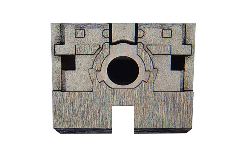
| Mechanical structure | Precision-molded insulating housing, contact support features, alignment guides and locking structures |
| Contact support | Supports RF signal, ground and power contacts; designed for stable contact pressure and minimal micro-movement |
| Compatible PCB types | Standard FR-4 and high-frequency PCB materials with surface-mount or through-hole landing patterns |
| Compatible FPC types | Flexible printed circuits with appropriate pitch and stiffener as required by the mating connector |
| Dielectric material | High-quality insulating plastic molded for dimensional stability and RF performance |
| Shielding & grounding | Can be combined with grounded contacts, metal frames or surrounding shielding structures for improved RF isolation |
| Operating environment | Suitable for typical industrial and communication environments; specific temperature and humidity ratings depend on chosen connector family |
| Assembly methods | Compatible with SMT reflow soldering for board-side parts; FPC side may use latch, slide, or flip-lock mechanisms |
| Customization options | Potential for custom mold geometries, keying features, and board stack heights to match your design |
Typical Use Cases & Applications
Board to board, FPC, RF mold parts are used wherever designers need compact, repeatable interconnects that still preserve RF performance. Some common scenarios include:
- Stacked RF and baseband boards
In wireless communication systems, RF front-end boards are often stacked above baseband or processing PCBs. Molded board-to-board interfaces provide consistent spacing and alignment while shortening RF paths between modules. - FPC-based antenna connections
Antennas on flexible substrates can be routed around housings or onto external surfaces. FPC connectors with RF-optimized mold parts provide a reliable interface between the flexible antenna and the main PCB. - Modular IoT and embedded platforms
To enable field serviceability and variant management, RF modules, radio cards or sensor boards can be connected via board-to-board RF interconnects using molded components that ensure mechanical stability. - Automotive & industrial RF systems
In harsh environments, robust molding and secure locking features help maintain connectivity despite vibration, temperature swings and exposure to contaminants, which is critical in automotive telematics, industrial gateways and wireless control systems. - Test and measurement fixtures
Custom jigs and fixtures for RF validation often rely on repeatable mating cycles. Molded RF interconnect sections can provide controlled geometry and repeatable performance across many insertions.
Selection & Buying Guidance
Selecting the right board to board, FPC, RF mold parts for your project involves balancing electrical, mechanical and manufacturing requirements. Consider the following points during design and sourcing:
- Define your RF requirements
Clarify the frequency range, power level and signal types that must pass through the interconnect. Higher frequencies and tighter margins generally demand short paths, controlled impedance and well-managed grounding around the mold parts. - Check mechanical constraints
Measure available board area, allowable stack height, and any enclosure limitations. Choose mold geometries and connector styles that fit the mechanical envelope while allowing for easy assembly and rework. - Align with PCB and FPC design
Confirm that your PCB and FPC layouts can support the required land patterns, keep-out areas, and stiffeners. Early collaboration between mechanical, RF and PCB designers will help avoid last-minute changes. - Assess assembly and rework needs
Consider whether your production line will use automated pick-and-place and reflow, or if manual processes are involved. Select components that provide clear visual alignment cues and robust mechanical support during soldering and rework. - Consider environment and reliability
For applications involving vibration, shock or wide temperature ranges, prioritize mold parts and connector families tested in such conditions. Locking mechanisms, reinforced housings and solid grounding structures can significantly improve long-term reliability. - Plan for scalability
If your design may evolve into a family of products, choose interconnect solutions with multiple pin counts, stack heights and configuration options. Consistent RF mold parts across your platform can simplify future development.
By carefully matching board to board, FPC, RF mold parts to your specific technical and manufacturing requirements, you can build RF subsystems that are both easier to produce and more robust in the field.
FAQ
Are these board to board, FPC, RF mold parts compatible with my existing RF connectors?
Compatibility depends on the specific connector family, pitch and mechanical interface used in your current design. In most cases, you will need to match the same or a closely related series of board-to-board or FPC connectors to ensure proper mating and RF performance. Reviewing datasheets and mechanical drawings is the best way to confirm compatibility.
What information do I need to choose the right mold parts for my design?
You should know the required number of signal and ground pins, target frequency range, board stack height, board and FPC thickness, and environmental conditions. Providing this information to your connector supplier or design team will help identify suitable mold geometries and connector styles.
How should I design the PCB footprint for these components?
Use the recommended land patterns from the connector manufacturer and follow RF layout best practices such as controlled impedance traces, short RF paths and appropriate ground stitching. Maintaining clear keep-out regions around the mold parts can also help with mechanical clearance and solder joint reliability.
Can these RF mold parts withstand lead-free reflow soldering?
Most modern connector systems and associated mold parts are designed to be compatible with standard lead-free reflow profiles. Always verify the maximum reflow temperature and recommended thermal profile in the relevant technical documentation before finalizing your process.
How do I maintain signal integrity when using board-to-board RF interconnects?
Keep interconnect paths as short as practical, maintain consistent impedance through the connector region, and provide solid grounding around critical RF pins. Use ground shields, vias and well-routed return paths to reduce crosstalk and emissions.
What is the typical lead time for sourcing board to board, FPC, RF mold parts?
Lead times vary by series and quantity. Common, standard connector families may be available from stock, while custom or less common configurations can require additional manufacturing time. Planning ahead and confirming availability with your supplier is recommended for production builds.
How should I clean or maintain assemblies using these RF components?
Completed assemblies should be cleaned according to your PCB manufacturing process guidelines, avoiding aggressive solvents that might attack plastic housings. During service, avoid mechanical stress on the interconnect regions and protect the connectors from contamination or corrosion.
What are the return or warranty considerations for these parts?
Warranty and return policies depend on the specific supplier. Generally, unused and undamaged components can be returned within a defined period, while parts that have been soldered or used in production may be subject to different terms. Check with your distributor or manufacturer for the exact conditions.
Can I request customized RF mold parts for a unique board outline?
Many connector manufacturers offer customization options, including modified housings, unique keying features or adjusted stack heights. Custom solutions may require engineering review, tooling, and additional lead time, but can provide an optimal match for complex mechanical designs.
Do these components support both RF and power signals in the same interface?
Yes, many board-to-board and FPC interfaces can combine RF, high-speed digital and low-voltage power contacts within the same housing. It is important to allocate adequate grounds and follow layout guidelines to avoid interference between different signal types.
Same drawing, predictable results—next batch
Share revision, quantity ramp, and inspection level. We quote process route, ship date, and documentation in one structured response.