
Plastic film parts · Precision mold insert
Board to Board, FPC, RF Mold Parts – Precision Connector Components for RF & High-Density PCBs Board to board, FPC,RF mold parts
Brand Xuxiang Mold
Availability Made to drawing
RFQ pricing
Quote from STEP / PDF & quantity
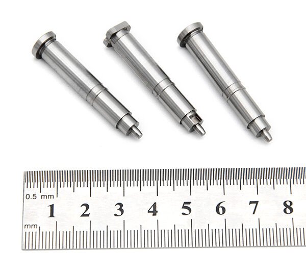
Engineered for modern high‑density electronics, these Board to board, FPC, RF mold parts provide reliable interconnection between rigid PCBs, flexible circuits and RF modules. Designed for precision fit in connector housings, they help reduce signal loss and improve mechanical stability in compact layouts. Robust molding and tight dimensional control support consistent performance under vibration and thermal cycling. Ideal for OEMs and EMS providers seeking dependable custom or semi‑custom connector components for RF, telecom, industrial and consumer devices.
(Board to board, FPC,RF mold parts)
- ISO 9001:2015–oriented process & documented inspection paths
- Zeiss / Nikon class metrology available for critical dimensions
- DFM feedback from 10+ senior tooling engineers
- Dongguan HQ + Quanzhou capacity for volume programs
Board to board, FPC,RF mold parts
Board to Board, FPC, RF Mold Parts – What They Are
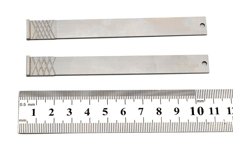
These Board to board, FPC, RF mold parts are precision‑engineered connector components used to create reliable electrical and mechanical links between printed circuit boards (PCBs), flexible printed circuits (FPCs) and RF modules. Rather than being a single finished connector, this product category focuses on the molded housing and associated parts that form the core structure of high‑density board‑to‑board and board‑to‑FPC connector systems.
They are typically used by connector manufacturers, OEMs and EMS providers who need stable, repeatable component geometry for high‑frequency and high‑pin‑count designs. In applications such as RF front‑end modules, wireless devices, IoT sensors, automotive electronics and industrial control equipment, these molded parts provide the backbone for signal integrity, precise mating alignment and mechanical protection.
By combining optimized mold design with materials suited to RF and high‑speed signals, these parts support compact layouts, fine pitch terminations and demanding operating environments. The result is a connector foundation that helps reduce noise, maintain impedance control and ensure long‑term reliability even under repeated mating cycles and environmental stress.
Key Features & Benefits
The value of high‑quality board to board, FPC and RF mold parts lies in how they improve system performance, manufacturability and durability. Key characteristics include:
- Precision‑molded geometry – Tight dimensional tolerances help ensure consistent contact positioning, accurate pitch and secure mating between boards and FPCs. This supports automated assembly and reduces alignment issues on densely populated PCBs.
- Optimized for RF and high‑speed signals – Mold designs can be tailored for controlled spacing, shielding features and contact routing that support stable impedance and low insertion loss in RF and high‑speed digital lines.
- Support for board‑to‑board and board‑to‑FPC configurations – Suitable for vertical and parallel board‑to‑board connectors, mezzanine stacks and flexible interconnects where an FPC links two or more rigid boards.
- Material options for demanding environments – Engineering plastics commonly used for these mold parts are selected for heat resistance, dimensional stability and compatibility with standard PCB reflow processes. This supports use in industrial, automotive and telecom electronics.
- Mechanical robustness – Mold features such as polarization keys, locking ribs and strain‑relief structures help protect solder joints and contacts from vibration, shock and cable pull forces.
- Design flexibility – Different pin counts, orientations and mounting styles (top entry, side entry, SMT or through‑hole tails) can be supported by variations of the mold parts, allowing customization around your board layout.
- Manufacturing efficiency – Consistent molded parts simplify connector assembly, reduce rework and support high‑volume, automated production with stable quality from lot to lot.
Specifications & Key Attributes
The exact specifications depend on the particular connector series and custom options, but the table below summarizes typical attributes considered when selecting board to board, FPC and RF mold parts.
| Attribute | Description |
|---|---|
| Product type | Precision molded parts for board‑to‑board, board‑to‑FPC and RF connector housings |
| Typical applications | RF front‑end modules, wireless devices, IoT sensors, telecom equipment, industrial and automotive electronics |
| Compatible interconnect styles | Board‑to‑board mezzanine connectors, FPC/FFC connectors, RF coaxial or hybrid signal/power connectors |
| Mounting orientation | Supports vertical or parallel board stacking; options for top or side entry depending on design |
| Pitch compatibility | Designed for fine‑pitch, high‑density layouts; specific pitch values depend on the connector series |
| Housing material | High‑performance engineering plastic chosen for heat resistance and dimensional stability |
| Electrical focus | Supports RF and high‑speed digital transmission with emphasis on signal integrity and controlled alignment |
| Environmental resistance | Suitable for typical electronics operating environments; specialized materials available for elevated temperature or vibration |
| Customization | Options for different profiles, keying features, locking mechanisms and contact/terminal layouts |
| Typical users | Connector manufacturers, OEM design teams, EMS providers and RF module designers |
Typical Use Cases & Who It Is For
Board to board, FPC and RF mold parts are used anywhere compact, reliable interconnects are critical to product performance. Common use cases include:
- RF communication modules – Smartphones, routers, IoT gateways and wireless access points rely on tightly controlled RF paths between transceivers, filters and antennas. Molded connector parts help maintain alignment and mechanical protection in these modules.
- High‑density embedded systems – Single‑board computers, industrial controllers and edge devices often stack multiple boards using mezzanine connectors built around precision mold housings.
- FPC‑based compact devices – Wearables, handheld instruments and slim consumer products frequently use FPCs to route signals in tight spaces. Board‑to‑FPC connectors using quality mold parts provide secure terminations without sacrificing form factor.
- Automotive and transportation electronics – Infotainment, ADAS and telematics modules benefit from robust connector housings that can endure vibration and temperature swings while preserving RF and signal integrity.
- Test and measurement equipment – RF instruments, spectrum analyzers and communication testers need repeatable connections with minimal signal degradation, supported by stable connector structures.
This product category is particularly suited to:
- Component and connector manufacturers seeking a reliable source of core molded parts.
- OEMs wanting to co‑develop custom connector solutions optimized for specific board layouts and RF paths.
- EMS providers assembling high‑volume boards who need connectors with stable, assembly‑friendly mechanical design.
Selection & Buying Guidance
Choosing the right board to board, FPC, RF mold parts is largely a matter of matching mechanical and electrical requirements to your product design. When specifying or ordering, consider the following points:
- Board layout and stacking height – Define the distance between boards, FPC routing paths and allowed component keep‑out areas so the molded parts can be tailored to your geometry.
- Pitch and pin count – Determine the signal density you need and select mold designs compatible with the target pitch and number of positions. Finer pitch will demand tighter tolerances.
- Signal type and frequency – For RF and high‑speed digital lines, share target frequencies and interface standards so the connector design can support adequate shielding, impedance control and spacing.
- Assembly process – Confirm whether your process uses reflow, wave soldering or mixed technology, and ensure the housing materials and footprints are compatible with your assembly and inspection equipment.
- Environmental conditions – Define expected operating temperature range, vibration levels and any exposure to moisture or contaminants so the material selection and mechanical design can be adapted.
- Regulatory or industry requirements – If your end product must meet specific standards (for example in automotive or industrial sectors), make sure the connector system, including molded parts, is designed with those requirements in mind.
Working closely with your supplier to share 3D models, PCB outlines and performance targets will help ensure the delivered mold parts integrate smoothly into your connector and overall product design.
FAQ
Are these Board to board, FPC, RF mold parts finished connectors?
No. These are the precision molded components used within board‑to‑board, FPC and RF connector systems. They form the structural housing and alignment features that support contacts and terminals, and are typically integrated into a complete connector assembly by connector manufacturers or OEMs.
How do I check compatibility with my PCB and FPC layout?
Provide your PCB and FPC drawings or 3D files, including pitch, pad layout, stacking height and keep‑out regions. The mold part design can then be matched or customized to ensure proper alignment, soldering footprint compatibility and mechanical clearance in your assembly.
Can these mold parts handle RF and high‑speed digital signals?
Yes. They are intended for use in connector systems that carry RF and high‑speed signals. By controlling geometry, spacing and housing features, they support stable routing and can help maintain signal integrity, provided they are used with contacts and PCB layouts designed for your target frequency range.
What information do I need to specify when ordering?
Typical information includes board‑to‑board distance or FPC bend constraints, required pitch and pin count, mounting orientation, anticipated operating environment and any special mechanical or regulatory requirements. Sharing this detail helps ensure the mold parts are matched to your application.
How are these parts shipped and packaged?
For production volumes, molded parts are usually supplied in trays, reels or bulk packaging suited to automated or semi‑automatic handling. The specific packaging format can be selected based on your assembly process and equipment.
Do I need special equipment to assemble connectors using these mold parts?
Most users integrate these parts within standard connector assembly lines or workstations. For PCB assembly, conventional surface‑mount or through‑hole processes are typically used once the connector is fully built. No unusual equipment is required beyond what is normally used for fine‑pitch connectors.
How should I store the mold parts before assembly?
Store in a clean, dry environment away from direct sunlight, excessive heat and dust. Keep the original packaging closed until use to prevent contamination that could affect assembly quality or mating performance.
What is the typical warranty or return policy?
Warranty and returns depend on the commercial agreement with your supplier. In most cases, defects in materials or workmanship identified within the agreed inspection period can be addressed through replacement or credit. Consult your sales representative or contract for specific terms.
Can I request custom designs or modifications?
Yes. Customization is common for board to board and FPC connector mold parts. Adjustments to profile, keying, locking features, stacking height and mounting style can often be made to better fit your target product design and performance requirements.
Same drawing, predictable results—next batch
Share revision, quantity ramp, and inspection level. We quote process route, ship date, and documentation in one structured response.