
Plastic film parts · Precision mold insert
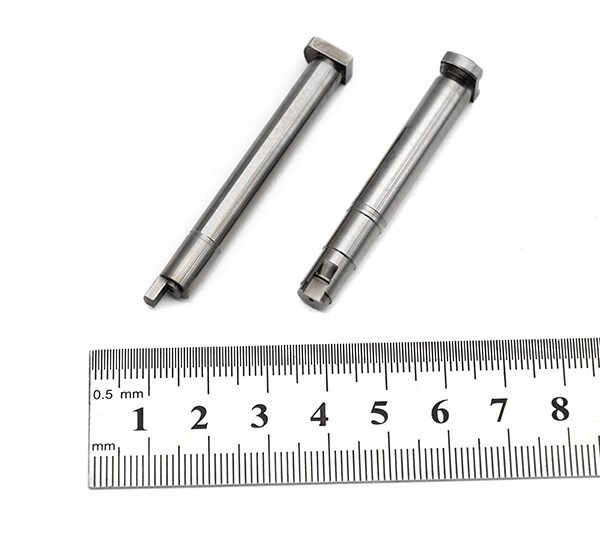
Board to Board, FPC, RF Mold Parts – Precision Connector Components for RF Devices Board to board, FPC,RF mold parts
Brand Xuxiang Mold
Availability Made to drawing
RFQ pricing
Quote from STEP / PDF & quantity
Engineered for demanding RF and high-speed digital applications, these Board to board, FPC, RF mold parts provide stable, low-loss interconnects between PCBs and flexible printed circuits. Precision-molded insulating structures and refined RF geometries help maintain signal integrity while optimizing layout flexibility in compact devices. Ideal for OEMs and EMS providers, the parts are designed to integrate smoothly into automated assembly lines and support reliable mass production. Whether you are developing wireless modules, IoT hardware, or compact consumer electronics, these components help you achieve consistent performance with a clean, robust mechanical design.
(Board to board, FPC,RF mold parts)
- ISO 9001:2015–oriented process & documented inspection paths
- Zeiss / Nikon class metrology available for critical dimensions
- DFM feedback from 10+ senior tooling engineers
- Dongguan HQ + Quanzhou capacity for volume programs
Board to board, FPC,RF mold parts
What Are Board to Board, FPC, RF Mold Parts?
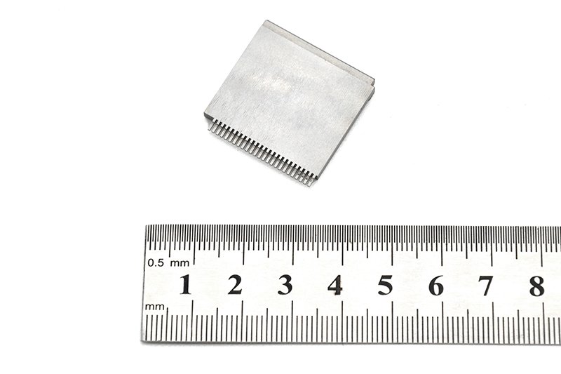
Board to board, FPC, RF mold parts are a family of precision connector and mechanical components used to create reliable electrical connections between printed circuit boards (PCBs), flexible printed circuits (FPCs), and RF circuits within compact electronic equipment. They typically combine:
- Board-to-board connector interfaces for stacking or mezzanine-style PCB connections.
- FPC connectors that mate with flexible printed circuits in cameras, displays, antennas, and sensors.
- RF-focused molded parts that provide controlled impedance, mechanical protection, and accurate positioning for high-frequency signal paths.
In modern electronics—such as smartphones, RF modules, routers, automotive control units, and industrial instruments—space is at a premium. Designers rely on compact connectors and molded RF structures to maintain signal integrity while still meeting tight mechanical constraints. These parts are designed around industry practices for FFC/FPC and board-to-board connectors, including narrow pitches, low profile heights, and robust contact systems optimized for vibration and thermal cycling.
Key Features & Benefits
Board to board, FPC, RF mold parts bring together mechanical precision and RF-aware design. The key advantages include:
- High-density interconnects: Fine-pitch terminations support compact layouts and multiple signal lines, allowing designers to reduce board size and overall device height.
- Optimized for RF performance: Molded geometries and carefully controlled contact positioning help support characteristic impedance and reduce reflection and insertion loss over RF paths.
- Reliable contact systems: Spring structures, multiple contact points, and secure retention mechanisms are commonly used to ensure stable electrical connections, even under shock, vibration, and temperature cycling.
- Flexible board and FPC coupling: Direct connection between FPCs and rigid boards eliminates the need for bulky harnesses, simplifying assembly and enabling more design freedom in 3D space.
- Automated-assembly friendly: Parts are designed with pick-and-place features, clear polarization, and solderable terminals suitable for SMT or reflow processes, supporting scalable production.
- Mechanical protection and strain relief: RF mold parts often act as shields, guides, and reinforcement structures, helping protect delicate FPC tails and high-frequency lines from bending and handling damage.
Together, these features make Board to board, FPC, RF mold parts an excellent choice for engineering teams that need repeatable RF performance and robust interconnects in a small form factor.
Specifications & Key Attributes
The exact specifications of board to board, FPC, RF mold parts will depend on your selected series and manufacturing partner. The following table summarizes typical attributes you can expect and can be used as a comparison guide when selecting specific components.
| Attribute | Description |
|---|---|
| Connector Types Supported | Board-to-board mezzanine, board-to-FPC, FPC/FFC connectors, and RF-focused molded coupling parts |
| Typical Applications | RF modules, wireless devices, IoT nodes, consumer electronics, automotive electronics, industrial control units |
| Pitch Range | Fine-pitch contact spacing suitable for high-density layouts (exact pitch depends on chosen series) |
| Mounting Style | Surface-mount or hybrid mounting compatible with standard reflow soldering processes |
| Mechanical Alignment | Polarized housings, alignment bosses, and molded guides for consistent mating and positioning |
| RF Considerations | Controlled geometry for impedance awareness, reduced discontinuities, and minimized RF loss |
| Material Options | High-temperature thermoplastics and copper alloy contacts with appropriate surface finishes (e.g. tin, gold, or nickel-based) |
| Environmental Robustness | Options designed for elevated operating temperatures, vibration, and automotive or industrial environments |
| Assembly Compatibility | Packaged for automated pick-and-place, tape-and-reel or tray configurations depending on component style |
| Compliance & Testing | Designed to meet common industry practices for mechanical reliability, durability, and electrical performance |
Use Cases & Who It Is For
Board to board, FPC, RF mold parts are designed for engineers and buyers across a wide range of electronics industries. They are particularly well suited to:
- RF module designers who need compact, repeatable connections between the RF front end, baseband, and antenna structures.
- Consumer electronics manufacturers building smartphones, tablets, wearables, and cameras, where tight enclosures require low-profile stacking and FPC routing.
- IoT and wireless device developers integrating multiple radios, sensors, and power-management boards into a single compact assembly.
- Automotive and transportation engineers implementing RF connectivity, infotainment systems, ADAS sensors, and telematics modules under demanding environmental conditions.
- Industrial and medical equipment manufacturers requiring stable, long-term interconnects with controlled RF behavior and efficient assembly.
These parts help teams save PCB space, simplify routing between rigid and flexible sections, and reduce design risk when working with high-frequency signals. By combining the right board-to-board connectors, FPC interfaces, and RF mold structures, you can streamline your mechanical concept, shorten development time, and create a cleaner, more serviceable design.
Selection & Buying Guidance
When specifying Board to board, FPC, RF mold parts for a new project or redesign, consider the following practical points:
- Electrical requirements: Start with your RF and high-speed signal needs, including target frequency range, expected insertion loss, and impedance requirements. Make sure the connector and molded path support your critical channels.
- Mechanical constraints: Define stack height, allowable footprint, keep-out areas, and FPC bending radius before choosing connector families. Confirm that the mechanical envelope leaves space for assembly tools and neighboring components.
- Assembly process: Verify compatibility with your existing SMT process, including reflow profiles, pick-and-place capabilities, and inspection methods. Consider whether top- or bottom-contact FPC interfaces are best for your line.
- Environmental conditions: For automotive or industrial applications, check that materials and designs are suitable for vibration, humidity, and temperature extremes. Look for options marketed specifically for harsh environments when appropriate.
- Mating cycles & durability: If the interface will be connected and disconnected during service, select parts with adequate rated mating cycles and robust mechanical design.
- Supplier ecosystem: Choose connector and mold-part families with broad availability, multiple pin-count options, and clear documentation to support long-term sourcing.
Discuss your requirements with your connector supplier or manufacturing partner, especially if you need custom RF mold geometries or specific FPC lengths and terminations. Combining standardized connectors with tailored molded RF parts often provides an attractive balance between performance, cost, and lead time.
FAQ
Are these Board to board, FPC, RF mold parts compatible with my existing PCB layout?
Compatibility depends on your board stack height, footprint, and routing clearances. In most cases, you can select a connector family and mold structure that aligns with common PCB pad layouts. It is recommended to share your current Gerber files and mechanical drawings with the supplier to confirm fit and propose any minor footprint adjustments.
How do I choose the right pitch and stack height?
Begin with the number of signals and available board space. A finer pitch and lower stack height help minimize size, but also demand tighter fabrication tolerances and assembly control. When in doubt, choose a pitch that your PCB fabricator and assembly house handle routinely, and verify stack height against your enclosure and neighboring components.
What should I consider for RF performance when selecting these parts?
For RF paths, focus on maintaining a consistent impedance along the entire signal chain. Pay attention to connector location, return path continuity, ground pin distribution, and any transitions between rigid boards and FPC. Work with your supplier to review recommended pad layouts and, if needed, perform simulation or TDR measurements on representative test boards.
Can these components be assembled using standard SMT and reflow processes?
Yes, most board-to-board and FPC connectors, along with associated RF mold parts, are designed for pick-and-place assembly and reflow soldering. Always follow the recommended reflow profiles, stencil thickness, and paste types specified in the product documentation to ensure optimal wetting and solder joint reliability.
How should I handle and install FPCs to avoid damage?
FPCs should be handled by their stiffeners or reinforced sections where possible, avoiding sharp bends near the contact area. During installation, ensure the FPC is fully inserted and held flat before locking the connector actuator. Observe minimum bend radius guidelines to prevent cracking or long-term fatigue.
What maintenance is required for these connectors in the field?
Under normal conditions, these parts require minimal maintenance. For serviceable assemblies, keep the mating areas free from dust, oils, and corrosive contaminants. If connectors are frequently mated and unmated, inspect for signs of wear or deformation and replace components that no longer hold a secure contact.
Do these parts come with any warranty or quality guarantees?
Warranty terms vary by manufacturer and distributor, but many offer standard warranties covering material and manufacturing defects for a defined period. Check with your sales representative or supplier for the specific warranty, reliability testing data, and quality certifications associated with your chosen series.
What are the shipping and lead-time considerations?
Lead times depend on configuration, order volume, and whether parts are standard or customized. Common connector variants are often stocked for quick shipment, while custom RF mold parts may require an engineering phase and tooling lead time. It is advisable to confirm availability and plan for buffer stock on long-running projects.
Can I request custom RF mold geometries or unique FPC lengths?
Many suppliers can support custom geometries, special FPC lengths, or tailored contact arrangements for higher-volume programs. Expect an engineering review, possible non-recurring tooling charges, and validation samples before full production. Early engagement with your supplier will help align technical requirements with cost and schedule.
What happens if the parts do not fit or perform as expected?
If the delivered components do not meet the agreed specifications, most suppliers will work through their returns and corrective-action process, which may include replacement, credit, or redesign support. Document your test results and provide clear feedback so issues can be diagnosed and resolved efficiently.
Same drawing, predictable results—next batch
Share revision, quantity ramp, and inspection level. We quote process route, ship date, and documentation in one structured response.