
Plastic film parts · Precision mold insert
Board to Board, FPC, RF Mold Parts High‑Precision Connector Components Board to board, FPC,RF mold parts
Brand Xuxiang Mold
Availability Made to drawing
RFQ pricing
Quote from STEP / PDF & quantity
Achieve reliable high-frequency signal transmission and compact interconnect layouts with these precision-engineered Board to board, FPC, RF mold parts. Designed for modern PCB, FPC and RF module integration, each mold part is manufactured to tight tolerances for stable impedance and long-term durability. Use them to simplify assembly, enhance structural rigidity, and improve repeatability across large production runs. Ideal for telecom, IoT, automotive electronics and consumer devices where space, performance and reliability are critical. Optimize your next connector design with parts ready for automated, high‑volume molding and overmolding workflows.
(Board to board, FPC,RF mold parts)
- ISO 9001:2015–oriented process & documented inspection paths
- Zeiss / Nikon class metrology available for critical dimensions
- DFM feedback from 10+ senior tooling engineers
- Dongguan HQ + Quanzhou capacity for volume programs
Board to board, FPC,RF mold parts
High‑Precision Board to Board, FPC, RF Mold Parts for Advanced Connector Designs
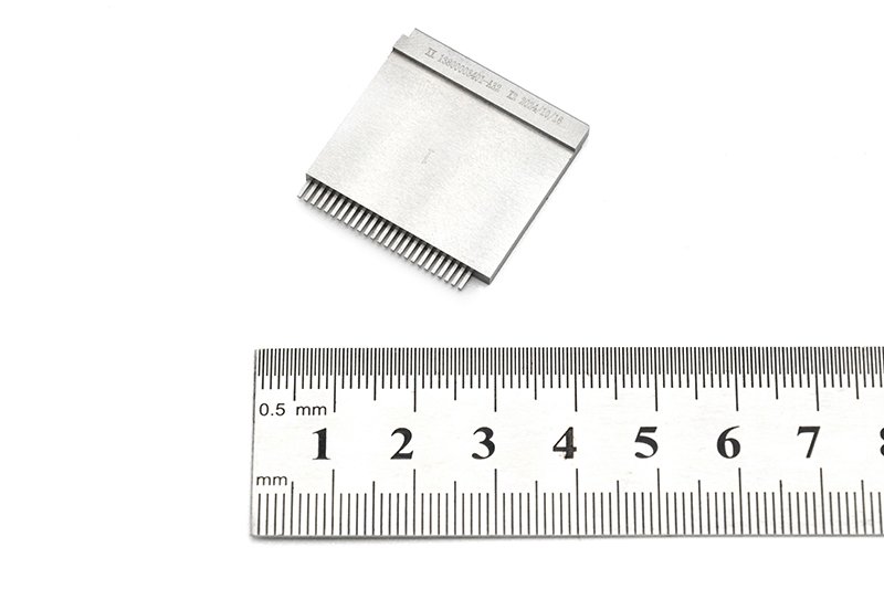
These Board to board, FPC, RF mold parts are specialized mechanical components used to build and protect high‑density electronic connectors, especially in applications where printed circuit boards (PCBs), flexible printed circuits (FPCs) and RF modules must be joined reliably in tight spaces. They provide the molded structure, alignment and shielding features that PCB and FPC electrical contacts require to maintain stable performance over the product’s lifetime.
Modern devices—from 5G base stations and small cells to automotive ADAS modules, wearables and industrial sensors—depend on compact, robust interconnects. Connector suppliers commonly combine micro‑pitch board‑to‑board and board‑to‑FPC interfaces with RF signal paths in single, miniature housings to reduce size and weight while preserving signal integrity.[2][5][10] High‑quality mold parts are essential to achieve consistent connector geometry, repeatable contact positioning, and proper isolation between RF and digital domains.
Key Features & Benefits
Engineered for demanding electronic assemblies, these mold parts support a range of connector architectures, including vertical and mezzanine board‑to‑board, board‑to‑FPC, and RF coaxial or multi‑line interfaces.[1][3][7][10]
- Optimized for mixed interconnects – Suitable for designs combining board‑to‑board, FPC and RF paths in one compact connector family, enabling streamlined layouts and fewer separate components.[2][5][10]
- Precise alignment and retention – Molded features guide mating connectors and FPC tails into the correct position, helping to prevent misalignment, fretting and intermittent contacts during assembly or vibration.[3][7][9]
- Support for high‑frequency RF performance – RF‑focused geometry and cavity design help maintain controlled impedance and consistent spacing around critical signal paths, which is important for GHz‑range connectors used in RF and microwave systems.[1][10][11]
- Compact, space‑saving design – Mold parts are tailored for narrow‑pitch and low‑profile connectors commonly used where board real estate and z‑height are limited, such as portable devices and compact control modules.[1][2][5][6]
- Mechanical protection for contacts – Robust housings shield delicate metal contacts and FPC fingers from handling damage, improving yield during SMT processes and field installation.[9][12][15]
- Support for automated production – Stable shapes and consistent dimensions make these mold parts suitable for automated assembly lines and high‑volume molding or insert‑molding operations, helping to lower per‑unit manufacturing costs.
- Material options for demanding environments – Connector mold components in this category are typically produced from engineering plastics intended for elevated temperature, chemical exposure and mechanical stress, including automotive under‑hood and industrial applications.[3][7][12]
Specifications & Key Attributes
The table below summarizes the typical characteristics you can expect from board‑to‑board, FPC and RF connector mold parts. Exact values will depend on the final connector design, chosen material and manufacturing process from your connector or OEM partner.
| Attribute | Description |
|---|---|
| Product type | Molded housing and mechanical parts for board‑to‑board, board‑to‑FPC and RF connectors |
| Compatible interconnects | Mezzanine board‑to‑board, FPC/FFC connectors, RF coaxial and multi‑line RF interfaces[1][2][5][10] |
| Typical applications | Telecom/5G, IoT devices, automotive electronics, industrial control, consumer electronics[3][5][7][10] |
| Typical materials | High‑performance engineering plastics suitable for SMT soldering and reflow; options for high‑temperature and automotive grades[3][7][12] |
| Mounting orientation | Supports vertical, horizontal and mezzanine stack connector orientations depending on design[2][5][6] |
| Supported cable/PCB types | Rigid PCBs, flexible printed circuits (FPC), and FFC ribbon cables for hybrid connections[2][9][13][15] |
| Pitch compatibility | Suitable for micro‑pitch and narrow‑pitch connector systems commonly used in compact electronics[1][2][6][10] |
| RF design considerations | Geometry allows routing and shielding features that help maintain RF signal integrity at high frequencies[1][10][11] |
| Environmental resistance | Options typically available for vibration‑resistant, high‑temperature and automotive‑grade applications[3][7][12] |
| Manufacturing process | Designed for injection molding, insert molding or overmolding as part of custom connector or module production |
Typical Use Cases & Applications
Because they provide the mechanical backbone of complex connectors, these mold parts are widely used wherever PCBs, FPCs and RF modules must be integrated in a small, reliable package.
- Telecommunications and RF systems – In base stations, remote radio heads, small cells and RF front‑end modules, mold parts support board‑to‑board and RF connector systems that handle high‑frequency signals while managing tight mechanical tolerances.[1][10][11]
- Automotive and transportation – Advanced driver assistance systems (ADAS), infotainment modules and sensor hubs often use board‑to‑FPC and RF connectors housed in robust, automotive‑qualified molded structures to withstand temperature cycling and vibration.[3][7]
- Industrial automation and control – PLCs, servo drives, machine vision and IIoT gateways employ compact board‑to‑board and FPC interconnects with dedicated RF links for wireless communication or high‑speed data, all supported by durable molded housings.[5][6][12]
- Consumer electronics and wearables – Smartphones, tablets, cameras and wearables rely on slim FPC connectors and RF feed‑throughs for antennas and displays. Mold parts provide the ultra‑compact housings and alignment features these designs require.[2][9][13][15]
- Medical and test equipment – Portable medical devices and RF test modules benefit from repeatable, high‑density connectors protected by robust molded frameworks, improving serviceability and lifetime.
Buying Guidance & Integration Tips
When selecting or specifying board‑to‑board, FPC and RF mold parts for your project, consider the following guidelines to ensure a good fit with your electrical design and production process.
- Define the connector architecture early – Decide upfront which signals will be routed via board‑to‑board, FPC and RF paths so that the mold design can incorporate correct cut‑outs, alignment features and shielding walls.[2][5][10]
- Coordinate with your connector vendor – Many board‑to‑FPC and RF connector solutions are offered as complete families by major manufacturers; aligning your mold requirements with available connector footprints can save time and tooling cost.[1][3][5][7][10][12]
- Validate RF performance – For high‑frequency designs, work with your RF and mechanical teams to simulate or prototype how the molded structure interacts with coaxial or stripline paths and any nearby ground structures.[1][10][11]
- Check assembly and rework access – Ensure the mold geometry allows pick‑and‑place access, soldering/reflow compatibility and, if needed, field rework of connectors on the PCB or FPC.[2][6][9][13]
- Consider environmental requirements – For automotive or industrial projects, confirm material options and test data for temperature range, flammability rating, and resistance to shock, vibration and chemicals.[3][7][12]
- Plan for manufacturing scale – Discuss tolerance control, gate placement and tooling design with your molder or connector supplier to achieve stable yields in high‑volume production.
By carefully matching your electrical connector strategy with the right mechanical mold parts, you can reduce overall system height, improve robustness, and shorten development time for complex electronic assemblies.
FAQ
Are these mold parts compatible with my existing board-to-board and FPC connectors?
Compatibility depends on your connector series, pitch and housing geometry. In most projects, mold parts are either matched to a specific connector family from a major manufacturer or customized around your PCB and FPC layout. Share your connector datasheets and board drawings with your supplier to confirm fit and alignment before ordering production quantities.[2][5][10][12]
Can these mold parts support high-frequency RF applications?
Yes, they are intended for use in RF assemblies where the mechanical structure must support stable, high‑frequency connectors. For best results, your RF engineer should review the cavity design, wall thickness and distance to ground to maintain consistent impedance and minimize reflections.[1][10][11]
What information do I need to provide when ordering custom Board to board, FPC, RF mold parts?
You should prepare PCB and FPC drawings, connector footprint details, target stack‑up height, expected environmental conditions, and any specific RF or shielding requirements. This allows the design team to propose suitable materials, molding processes and tolerance schemes tailored to your application.
How should I handle and store these mold parts before assembly?
Store parts in their original packaging in a clean, dry environment away from direct sunlight and extreme temperatures. Avoid stacking heavy objects on top of trays or reels. During handling, prevent contamination with oils, dust or debris that could interfere with connector seating or soldering.
Are these mold parts suitable for lead-free reflow soldering processes?
Connector mold components in this category are generally designed to withstand standard lead‑free reflow profiles when used as part of a complete connector system.[3][7][12] Always verify the recommended temperature limits and reflow profile with your connector or mold supplier and validate in your own process.
What is the typical lead time for custom mold designs?
Lead time varies with design complexity and tooling requirements. As a guideline, allow additional time for design review, prototype trials and any tuning needed after initial samples. Discuss project milestones early with your supplier to align the mold schedule with your PCB and FPC development.
How do I ensure proper alignment between the mold parts, PCBs and FPCs?
Use dedicated datum features, alignment pegs and cut‑outs that reference known board holes or edges. Early mechanical co‑design between your PCB layout engineer and mold designer helps avoid interference issues and ensures consistent mating across production lots.[3][7][9]
What kind of warranty or returns policy is typical for these components?
Warranty terms are usually linked to conformance with agreed drawings and material specifications. In case of issues such as dimensional non‑conformance or molding defects, suppliers generally offer replacement or credit after evaluation. Clarify acceptance criteria, inspection plans and return procedures as part of your purchasing agreement.
Can I get small prototype quantities before committing to full tooling?
Many projects begin with small batches produced via soft tooling, 3D printing for fit checking, or limited pilot molds. Ask your supplier about available prototyping options and how they correlate with the final production process to ensure that results scale correctly.
How do these mold parts impact overall connector reliability?
Well‑designed mold parts improve connector reliability by protecting contacts, controlling mating alignment and preserving the intended mechanical stack‑up over time.[3][7][9][12] They help connectors maintain consistent contact force, minimize fretting corrosion and reduce damage from mechanical shock or vibration.
Same drawing, predictable results—next batch
Share revision, quantity ramp, and inspection level. We quote process route, ship date, and documentation in one structured response.