
Plastic film parts · Precision mold insert
Board to Board, FPC, RF Mold Parts – Precision RF & Signal Interconnect Components Board to board, FPC,RF mold parts
Brand Xuxiang Mold
Availability Made to drawing
RFQ pricing
Quote from STEP / PDF & quantity
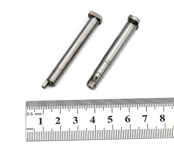
Ensure reliable high‑frequency and signal transmission in compact electronics with these precision Board to Board, FPC, RF mold parts. Designed for modern PCB and flexible circuit layouts, they help you create stable interconnects in RF front‑ends, IoT modules, communication devices, and embedded systems. Robust molded housings and optimized contact structures support consistent impedance and contact reliability in demanding environments. Integrate them into your designs to reduce assembly complexity, save space, and improve long‑term performance. Ideal for OEMs, EMS providers, and RF design engineers seeking dependable, integration‑ready interconnect solutions.
(Board to board, FPC,RF mold parts)
- ISO 9001:2015–oriented process & documented inspection paths
- Zeiss / Nikon class metrology available for critical dimensions
- DFM feedback from 10+ senior tooling engineers
- Dongguan HQ + Quanzhou capacity for volume programs
Board to board, FPC,RF mold parts
What Are Board to Board, FPC, RF Mold Parts?
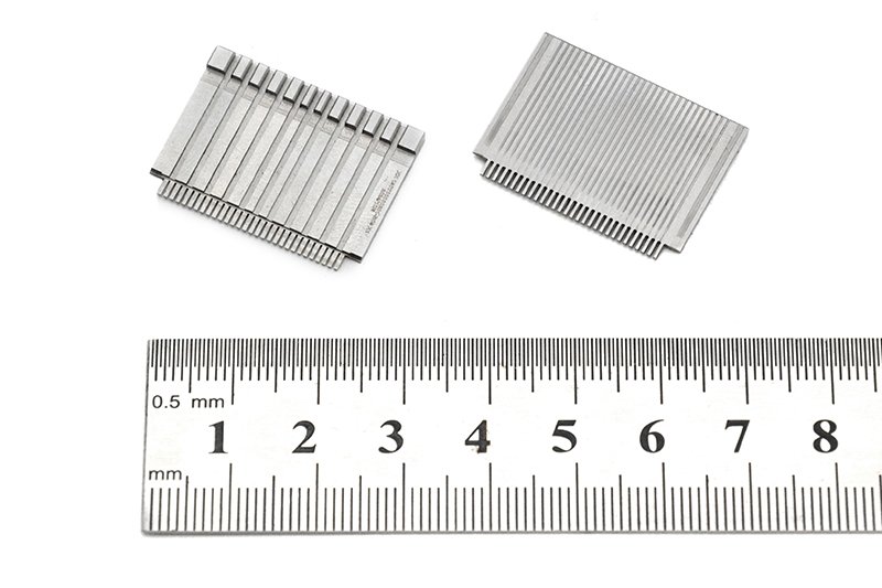
Board to board, FPC, RF mold parts are a family of precision interconnect and mechanical components used to connect printed circuit boards (PCBs), flexible printed circuits (FPCs), and RF modules within electronic devices. They typically combine high‑density connector structures with molded insulating bodies and RF‑optimized geometry to maintain consistent signal integrity across board‑to‑board and board‑to‑FPC interfaces.
In modern electronics, designers often need to stack multiple PCBs, route signals through thin flexible cables, and integrate RF front‑ends tightly with digital logic. Board‑to‑board connectors provide vertical or horizontal stacking between rigid PCBs, while FPC connectors interface to flexible printed circuits used as space‑saving harnesses or dynamic interconnects. RF mold parts add mechanical stability, controlled impedance, and shielding features that are especially important at high frequencies.
These components are widely used in applications such as wireless communication equipment, IoT devices, automotive electronics, industrial control systems, medical instruments, and consumer electronics where compact, reliable, and repeatable interconnections are critical.
Key Features & Benefits
When you specify board to board, FPC, RF mold parts in your design, you gain a combination of electrical performance, mechanical robustness, and assembly efficiency. Key characteristics typically include:
- High‑density interconnect capability – Fine‑pitch board‑to‑board and FPC connectors support compact layouts with multiple signal and RF lines in a very small footprint, ideal for space‑constrained enclosures.
- Optimized for RF performance – RF mold parts are shaped and dimensioned to help maintain more consistent characteristic impedance and reduce reflections and loss over the RF path, supporting stable operation of antennas, transceivers, and front‑end modules.
- Reliable board‑to‑FPC transitions – Dedicated FPC connectors provide secure clamping of flexible printed circuits, supporting repeated insertions and withstanding vibration when mated correctly.
- Mechanical stability and strain relief – Molded housings and integrated features such as positioning pegs, boss structures, and locking mechanisms help distribute mechanical loads and reduce stress on solder joints or FPC conductors.
- Support for automated assembly – Many parts are designed with pick‑and‑place friendly geometries and packaging, allowing surface‑mount assembly and reflow processes commonly used in high‑volume production.
- Versatile mounting orientations – Board‑to‑board connectors may support vertical, mezzanine, or right‑angle configurations, while FPC connectors can be top or bottom contact, supporting a broad range of mechanical stack‑ups.
- Durable contact materials – Spring contacts and terminal structures generally use copper‑alloy materials with protective plating to preserve contact reliability over many mating cycles and under environmental stress.
Specifications & Core Attributes
The exact specifications will vary by series and manufacturer, but the following table summarizes the typical attributes you should consider when selecting board to board, FPC, RF mold parts for your project.
| Attribute | Description |
|---|---|
| Connector Type | Board‑to‑board mezzanine connectors, board‑to‑FPC connectors, and RF‑specific molded interconnect parts |
| Typical Applications | RF front‑end modules, wireless devices, IoT nodes, automotive control units, industrial and medical electronics |
| Pitch / Density | Fine‑pitch geometries suitable for high‑density layouts; select series based on your required pin count and spacing |
| Mounting Style | Surface‑mount or through‑hole board‑to‑board; ZIF or non‑ZIF FPC connectors; molded RF parts tailored for PCB edge or module mounting |
| Contact Configuration | Signal, ground, and RF paths arranged for controlled impedance and improved signal integrity |
| Housing / Mold Material | High‑temperature, insulation‑grade molding materials compatible with standard reflow soldering profiles |
| Operating Environment | Engineered to withstand typical electronics operating conditions; some series suitable for more demanding industrial or automotive use |
| Mating Orientation | Vertical stacking, horizontal (right‑angle), or parallel board connections; front‑flip or back‑flip FPC insertion styles |
| Signal Types | High‑speed digital signals, RF signals, low‑level control lines, and power rails within the rated current and voltage range |
| Compliance & Standards | Specific certifications vary by series; check datasheets for safety, environmental, and industry compliance details |
Use Cases & Who These Parts Are For
Board to board, FPC, RF mold parts are suitable for a wide range of engineers and organizations working on compact, interconnected electronics. Typical use cases include:
- Wireless communication devices – Smartphones, tablets, handheld radios, and IoT gateways where RF sections must be tightly integrated with baseband and control boards.
- IoT sensors and modules – Battery‑powered sensor nodes or RF modules where FPC cables and board‑to‑board connectors allow flexible placements inside enclosures.
- Automotive and transportation electronics – Control units, infotainment systems, ADAS modules, and telematics devices that require stable connections under vibration and temperature variation.
- Industrial and factory automation – Compact control boards, PLC modules, and RF communication nodes that must be serviceable and modular.
- Medical and laboratory equipment – Portable diagnostic instruments, imaging accessories, and monitoring devices where space is limited and interconnect reliability is critical.
- Consumer and wearable electronics – Compact devices such as cameras, audio products, and wearables where FPCs carry signals through hinges, bends, and tight curves.
These parts are especially valuable to design engineers, hardware architects, and manufacturing engineers in OEMs and EMS providers who need to achieve consistent high‑frequency performance, minimize assembly errors, and maintain flexibility for future design changes.
Selection & Buying Guidance
Choosing the right combination of board to board, FPC, and RF mold parts for your product involves a balance between electrical performance, mechanical design, and manufacturing considerations. Use the guidelines below to narrow your options.
- Define your stack‑up and geometry – Determine board spacing, orientation, and available envelope inside the enclosure. This will drive connector height, mating direction, and whether you need vertical, right‑angle, or offset configurations.
- Clarify signal and RF needs – Identify which lines are high‑speed digital, which are RF, and which carry power or low‑speed control. Use parts with suitable contact arrangements and RF‑optimized features for the most critical paths.
- Consider FPC routing – If you are using flexible printed circuits, confirm the bend radius, insertion direction, and retention forces. Select FPC connectors that support your cable thickness and plating while fitting the layout constraints.
- Match to your assembly process – Make sure chosen components are compatible with your pick‑and‑place equipment, reflow profile, and inspection methods. Look for features such as alignment tabs and clear polarity markers to reduce errors.
- Evaluate environment and lifecycle – For demanding applications (such as automotive or industrial), focus on series rated for higher temperature ranges, improved vibration resistance, and suitable durability over the expected number of mating cycles.
- Check documentation and samples – Before locking in a design, review manufacturer datasheets, recommended land patterns, and evaluation boards when available. Using samples early in the prototype phase helps avoid costly revisions later.
By carefully matching your electrical and mechanical requirements to the available board to board, FPC, RF mold parts, you can simplify your interconnect strategy, improve reliability, and streamline production from prototype through volume manufacturing.
FAQ
Are these board to board, FPC, RF mold parts suitable for high‑frequency RF designs?
Yes. Many board to board and FPC components in this category are specifically shaped and dimensioned to support stable impedance and low loss at RF and high‑speed digital frequencies. Always confirm the recommended frequency range and layout guidelines in the relevant datasheet for your target application.
How do I check compatibility with my existing PCBs and FPCs?
Review the mechanical drawings and recommended land patterns for the parts and compare them with your PCB stack‑up and FPC dimensions. Pay special attention to pitch, contact count, insertion direction, and board spacing. Ordering a small quantity of samples for trial assembly is strongly recommended before committing to production tooling.
Can these connectors and mold parts handle repeated mating cycles?
Most board to board and FPC connectors are designed for a defined number of mating cycles, which is specified by the manufacturer. For applications that require frequent disconnects, choose series with higher durability ratings and avoid overstressing the FPC or PCB during insertion and removal.
What should I consider for assembly, soldering, and rework?
Follow the manufacturer’s recommended reflow profile and land pattern to avoid damaging the molded housing or misaligning contacts. For rework, use controlled hot‑air and appropriate tools to avoid lifting pads or overheating nearby components. Always support the PCB and FPC mechanically during any manual operations.
How do I maintain signal integrity across board‑to‑board and FPC links?
Use controlled‑impedance traces on your PCBs and FPCs, match reference planes, and follow any layout examples provided by the connector vendor. Keep RF and high‑speed traces as short and direct as possible within the connector area and minimize stubs or abrupt changes in geometry.
What are the typical shipping and lead time expectations?
Lead times depend on the specific series and order quantity. Common configurations are often available from stock or with short lead times, while highly customized or less common variants may require longer production windows. Plan ahead for pre‑production sampling and buffer time for volume orders.
Are there special storage or handling requirements?
Store the parts in their original packaging in a dry, clean environment. Avoid contaminating the contacts with oils or dust, and handle with ESD‑safe measures when working around sensitive electronic assemblies. For moisture‑sensitive items, follow any specified dry‑pack or bake guidelines.
What is the recommended approach if I need a different pitch or orientation later?
Many connector families offer multiple pitches, heights, and orientations within the same product series. Selecting a modular, widely supported family during the initial design gives you more flexibility to adjust pin count or mechanical layout in future product revisions without a complete redesign.
How do returns or warranty claims typically work for these components?
Policies depend on the distributor or manufacturer you purchase from. In general, unused and unopened reels or trays can often be returned within a defined period, subject to their terms. For suspected defects, you may be asked to provide batch information and failure details so the supplier can evaluate and support a suitable resolution.
Same drawing, predictable results—next batch
Share revision, quantity ramp, and inspection level. We quote process route, ship date, and documentation in one structured response.