
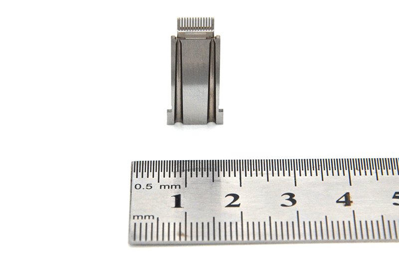
Plastic film parts · Precision mold insert
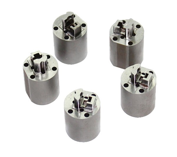
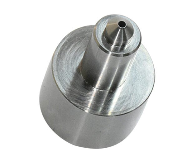
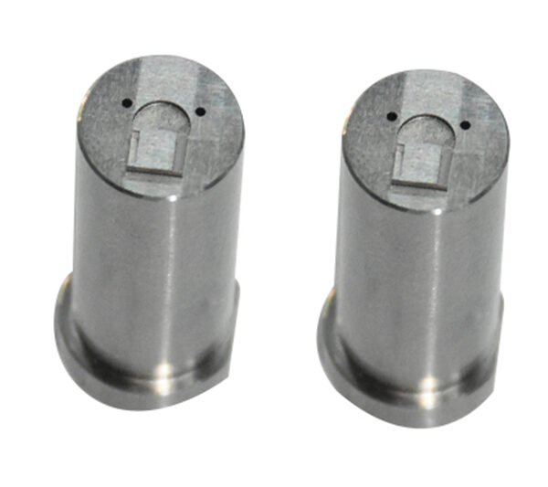
Board to Board, FPC, RF Mold Parts – Precision Connector & RF Molding Components Board to board, FPC,RF mold parts
Brand Xuxiang Mold
Availability Made to drawing
RFQ pricing
Quote from STEP / PDF & quantity
Engineered for modern electronics, these precision Board to Board, FPC, RF mold parts deliver reliable high-density interconnects in compact designs. Designed to support high-frequency RF signals and flexible printed circuits, they help you simplify layouts and reduce wiring harness complexity. Robust molding and tight tolerances ensure stable mechanical strength and consistent impedance performance in demanding environments. Ideal for consumer electronics, automotive modules, IoT devices and RF communication boards, they integrate seamlessly into SMT production lines. Choose them to enhance signal integrity, improve assembly efficiency and extend product lifecycle.
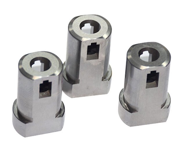
(Board to board, FPC,RF mold parts)
- ISO 9001:2015–oriented process & documented inspection paths
- Zeiss / Nikon class metrology available for critical dimensions
- DFM feedback from 10+ senior tooling engineers
- Dongguan HQ + Quanzhou capacity for volume programs
Board to board, FPC,RF mold parts
High‑Reliability Board to Board, FPC, RF Mold Parts for Modern Electronics
Our Board to Board, FPC, RF mold parts are a specialized family of connection and molding components designed for compact, high‑performance electronic assemblies. By combining board‑to‑board interconnect technology, FPC (Flexible Printed Circuit) interfaces and RF‑optimized molding parts, this product range helps design engineers achieve higher signal density, better RF performance and simplified mechanical integration.
These parts are commonly used in applications where you need to connect multiple printed circuit boards, integrate flexible circuits, and carry radio‑frequency signals without compromising signal integrity. Typical target sectors include smartphones and tablets, automotive ECUs and camera modules, RF front‑end modules, wearable devices, industrial controllers and IoT hardware, where miniaturization and reliability are critical.
Instead of relying on bulky wiring harnesses or multiple discrete connectors, the combination of board‑to‑board and FPC interfaces allows direct, low‑profile connections between PCBs and flexible circuits, while the RF molding components provide mechanical protection, controlled geometry around RF paths and improved environmental robustness.
Key Features & Benefits
- Integrated Board‑to‑Board & FPC Connectivity
Designed to accommodate both rigid PCB‑to‑PCB and flexible circuit terminations, reducing the number of different connector types in your design and simplifying the BOM. - Optimized for RF and High‑Speed Signals
RF mold parts and tailored connector geometries help support controlled impedance and minimize insertion loss, crosstalk and reflection over RF and high‑speed digital lines. - Space‑Saving, Low‑Profile Form Factors
Fine‑pitch and slim housing concepts enable tight stacking heights and edge‑to‑edge connections, ideal for compact consumer and automotive electronics where board space is constrained. - Mechanical Robustness and Strain Relief
Molded housings, shielding options and integrated retention features help protect solder joints and contacts against vibration, shock and repeated mating cycles. - Flexible Design Options
Available in multiple orientations (parallel or right‑angle), stacking heights, and contact counts, supporting a variety of board layouts and 3D packaging approaches. - Simplified Assembly & Automation‑Friendly
Pick‑and‑place compatible packaging, clear polarization features and mechanical alignment guides help reduce assembly errors and support high‑volume SMT production. - Suitable for Demanding Environments
Engineered to handle applications with temperature cycling, vibration and potential contamination, as typically found in automotive, industrial and wireless infrastructure equipment.
Specifications & Key Attributes
The table below summarizes the core attributes of the Board to Board, FPC, RF mold parts family. Specific values can vary by exact part number and configuration, but this overview helps you understand the general capability envelope.
| Attribute | Description |
|---|---|
| Product type | Board‑to‑board connectors, FPC connectors and RF‑optimized molding components for electronic assemblies |
| Typical applications | Consumer electronics, automotive modules, RF front‑end units, IoT devices, industrial control, communication equipment |
| Connection styles | PCB‑to‑PCB mezzanine, PCB‑to‑FPC, FPC termination with RF shielding or molded housings |
| Mounting method | Surface‑mount technology (SMT) for automated pick‑and‑place; some parts may support through‑hole pegs for alignment |
| Pitch range | Fine‑pitch contacts suitable for high‑density layouts; exact pitch depends on selected series or custom design |
| Supported signals | RF signals, high‑speed differential pairs and standard digital/analog I/O |
| Mechanical features | Polarization keys, retention clips, metal fittings, molded strain‑relief and optional shielding structures |
| Materials | High‑temperature thermoplastic housing, copper‑alloy contacts with suitable plating, RF‑grade molding compounds |
| Operating environment | Designed for use in typical electronics conditions, with options for elevated temperature and vibration‑prone environments |
| Customization | Custom cavity design, contact layout, RF molding geometry and logo/marking options available on request |
Use Cases & Who It Is For
Board to Board, FPC, RF mold parts are a strong fit for engineers and buyers who need to combine robust interconnect performance with aggressive miniaturization and RF‑friendly design. Some representative use cases include:
- Mobile & Consumer Devices
Connecting main logic boards to camera modules, displays and antennas using rigid‑flex and FPC assemblies, while keeping the RF path short and shielded. - Automotive Electronics
Integrating camera, radar, infotainment and telematics modules with reliable board‑to‑board and board‑to‑FPC interfaces that can tolerate vibration and temperature excursions. - RF Front‑End and Wireless Infrastructure
Housing and protecting RF filters, PA modules or antenna switches inside molded RF structures, with precise connector alignment for minimal mismatch. - Industrial & IoT Devices
Supporting compact control boards and sensor interfaces that require flexible interconnect and high signal integrity in tight housings. - Wearables & Medical Electronics
Enabling thin, lightweight devices where flexible circuits and miniature RF modules must coexist in a small enclosure without sacrificing reliability.
These parts are especially suitable for OEMs, EMS providers and design houses that need a scalable interconnect platform, as well as procurement teams seeking to standardize on a common board‑to‑board and FPC interface strategy across multiple product lines.
Selection & Buying Guidance
Choosing the right combination of board‑to‑board, FPC and RF mold parts requires balancing electrical performance, mechanical constraints and manufacturing considerations. When specifying parts for your project, consider the following factors:
- Signal Type and Frequency
Identify whether the interconnect will carry low‑speed digital, high‑speed serial links or RF signals, and select connector and molding options that support the required bandwidth and impedance control. - Board Stack‑Up and Geometry
Define board spacing, orientation (parallel or right‑angle) and allowable connector footprint; this will guide your choice of stacking height, entry direction and mounting style. - FPC Characteristics
Confirm FPC thickness, stiffness, bend radius and pad layout, and check compatibility with the chosen FPC connector series and any associated RF molding or strain‑relief parts. - Environmental Requirements
Assess temperature range, expected vibration levels, potential exposure to dust or moisture and any relevant compliance needs, then choose housings and materials that are suitable for those conditions. - Assembly Process
Align the parts with your manufacturing strategy: SMT reflow profile, inspection methods, handling fixtures and any requirements for automated FPC insertion or connector mating on the line. - Future Service & Modularity
Decide whether modules should be replaceable or upgradeable, and design the board‑to‑board and FPC interfaces to support field service or variant configurations without major redesign.
For volume projects or applications with unique mechanical envelopes, you may also consider custom RF mold parts that follow your enclosure shape and grounding scheme, ensuring optimal shielding and consistent RF performance from prototype through mass production.
FAQ
Are these Board to Board, FPC, RF mold parts compatible with standard SMT assembly?
Yes. The connectors and molded components are designed for standard SMT processes, including automated pick‑and‑place and reflow soldering. Always review the recommended land patterns and reflow profiles in the technical documentation for the specific part number you select.
How do I ensure compatibility with my existing FPC designs?
Check key parameters such as FPC thickness, pad pitch, pad plating and stiffener layout against the connector datasheet. If your current FPC design is non‑standard, you may need to adjust pad geometry or engage your supplier to match the connector series used in these parts.
Can these parts handle high‑frequency RF signals reliably?
The RF mold parts and matching connectors are intended to support RF and high‑speed signals when used with appropriate layout and grounding practices. Proper impedance control on the PCB and FPC, as well as correct alignment and shielding, are crucial for optimal performance.
What is the typical lead time and shipping arrangement?
Lead times vary based on configuration and order quantity. Standard configurations are usually available from stock or with short lead times, while customized RF molding or special pitches may require additional manufacturing time. Shipping options typically include standard and expedited services; consult your sales representative or distributor for current availability.
Do I need special tools to mate or unmate the FPC connectors?
Most FPC connectors in this family are designed for manual operation without special tools, using flip‑lock or slide‑lock mechanisms. For high‑volume production, some customers use simple insertion jigs to improve consistency and reduce handling stress on the FPC.
How should I care for and handle these RF mold parts during assembly?
Handle the parts with ESD protection and avoid touching the contact areas. Keep them in original packaging until use, store in a dry environment and follow any moisture‑sensitive device (MSD) guidelines provided by the manufacturer.
What is the recommended way to clean assembled boards using these connectors?
If cleaning is required after soldering, use cleaning methods and solvents approved for use with high‑temperature plastics and contact plating. Avoid aggressive chemicals or high‑pressure sprays that could force contaminants into the connector housing.
Is there a warranty or return policy for defective parts?
Warranty and return terms depend on the distributor and manufacturer policies, but typically cover defects in materials or workmanship identified under normal use. Contact your supplier with the lot number and application details if you suspect a defect so they can initiate evaluation and support a replacement if warranted.
Can I request custom RF molding geometry or connector configurations?
Yes. For projects with specific mechanical or RF requirements, many suppliers can support custom mold cavities, contact layouts or housing features. Provide your 3D models, electrical requirements and expected volumes to discuss feasible customization options.
What documentation should I review before integrating these parts into my design?
Always review the detailed datasheet, recommended PCB footprints, FPC design guidelines, 3D models and any available application notes. These resources help ensure correct mechanical fit, electrical performance and manufacturability in your end product.
Same drawing, predictable results—next batch
Share revision, quantity ramp, and inspection level. We quote process route, ship date, and documentation in one structured response.