
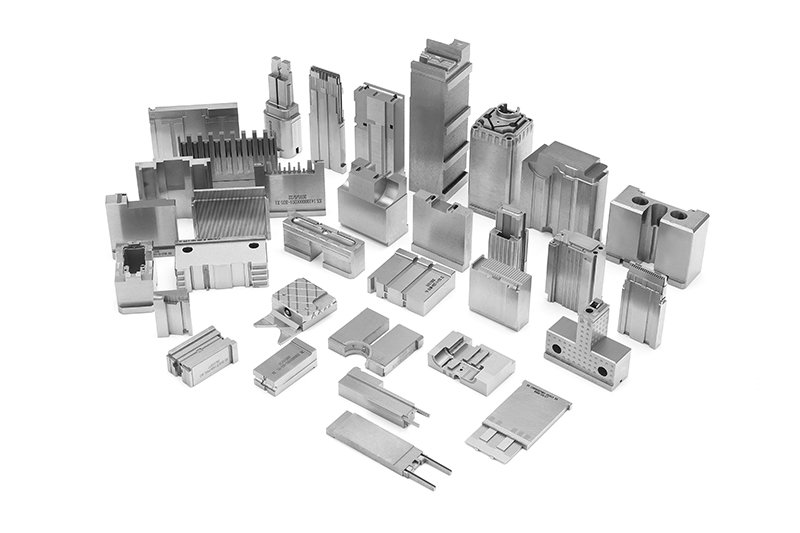
Plastic film parts · Precision mold insert
Board to Board, FPC, RF Mold Parts – Precision Connector Components for RF & High‑Density PCBs Board to board, FPC,RF mold parts
Brand Xuxiang Mold
Availability Made to drawing
RFQ pricing
Quote from STEP / PDF & quantity
Optimize your RF and high-density PCB designs with precision-engineered Board to board, FPC,RF mold parts. These connector components are designed for reliable signal integrity, compact stacking heights, and stable mechanical performance in demanding electronic assemblies. From flexible printed circuit (FPC) terminations to miniature RF interfaces, each mold part is produced with tight tolerances for consistent fit and long-term durability. Ideal for consumer electronics, automotive modules, IoT devices, and communication equipment where every millimeter of space and every dB of performance matters.
- ISO 9001:2015–oriented process & documented inspection paths
- Zeiss / Nikon class metrology available for critical dimensions
- DFM feedback from 10+ senior tooling engineers
- Dongguan HQ + Quanzhou capacity for volume programs
Board to board, FPC,RF mold parts
High‑Precision Board to Board, FPC, RF Mold Parts for Modern Electronics
As electronic devices become smaller, faster, and more integrated, the demands placed on interconnect technology increase dramatically. Board to board, FPC, RF mold parts are specialized connector components used to create reliable electrical and mechanical links between printed circuit boards (PCBs), flexible printed circuits (FPCs), and RF signal paths in compact assemblies.
These parts typically include molded housings, insulators, alignment features, contact supports, and RF shielding elements that work together with metal contacts and spring structures to deliver stable performance. They are a key enabler in smartphones, tablets, wearables, automotive control units, RF front-end modules, industrial control boards, and many other high‑density systems where space is tight and signal integrity is critical.
What These Mold Parts Are and How They Are Used
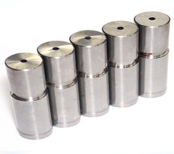
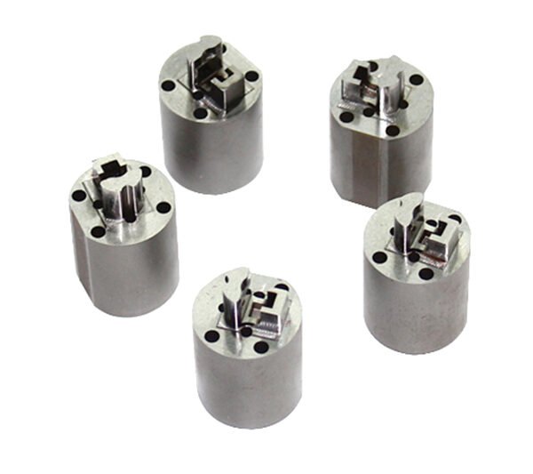
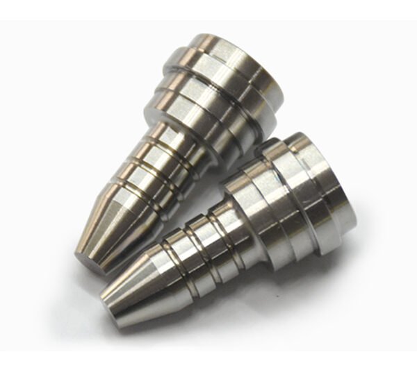
In connector design, plastic or resin mold parts serve as the structural and insulating backbone of the interconnect system. For board-to-board and FPC connectors, molded components define pitch, stacking height, insertion angle, and locking mechanisms. For RF connectors and RF modules, molded parts can also form cavities, shielding interfaces, and controlled geometries that help maintain characteristic impedance and reduce crosstalk.
Typical categories within this product family include:
- Board-to-board connector mold parts – housings, headers, receptacle bodies, spacers, and guide posts that support mezzanine and parallel stacking connectors.
- FPC connector mold parts – low-profile housings, actuator levers, covers, and strain-relief structures for flexible printed circuit termination.
- RF mold parts – precision-molded insulators, dielectric supports, and over-mold structures used in RF jacks, plugs, coaxial modules, and antenna interfaces.
These parts are typically produced from high-performance engineering plastics to meet demanding requirements for dimensional stability, soldering temperature endurance, and environmental reliability. The materials and geometry are carefully chosen to support repeated mating cycles, maintain proper contact pressure, and minimize signal loss.
Key Features & Benefits
- High‑density integration
Board-to-board and FPC mold parts are designed for fine-pitch connectors, enabling compact layouts, low stacking heights, and efficient use of PCB real estate in space-constrained devices. - Reliable mechanical alignment
Guide posts, polarization keys, and molded alignment features help prevent mis‑mating, reduce insertion force, and protect delicate contacts during assembly and servicing. - Stable RF performance
Specialized RF mold parts use controlled dielectric materials and geometries to support impedance‑controlled RF paths, reduce VSWR, and minimize insertion loss in RF front-end and antenna circuits. - Durable in harsh environments
High-temperature and high-strength plastics support lead‑free reflow soldering profiles and continuous operation in automotive, industrial, and telecom environments. - Optimized for FPC flexibility
Mold structures for FPC connectors consider bending radius, clamping force, and strain relief to protect flexible printed circuits from damage over time. - Manufacturing efficiency
Consistent molded geometry ensures predictable automated assembly, pick-and-place handling, and reliable solder joint formation, reducing rework and field failures.
Key Attributes & Reference Specifications
The exact specifications of board-to-board, FPC, and RF mold parts vary by series and design. The table below summarizes typical attributes to consider when selecting the right components for your application.
| Attribute | Board-to-Board Mold Parts | FPC Mold Parts | RF Mold Parts |
|---|---|---|---|
| Typical Application | Mezzanine PCB stacking, module interconnects, daughter boards | Flexible PCB termination, hinge connections, compact device links | RF front-end modules, antenna ports, coaxial jumpers, RF shields |
| Pitch & Form Factor | Fine-pitch, low to medium stacking heights; multiple row options | Ultra-low profile, narrow pitch; top or bottom contact styles | Compact coaxial or modular forms with controlled RF geometry |
| Primary Materials | High-temperature engineering plastics (connector housings) | Heat-resistant plastics, actuators, and covers optimized for FPC | RF-grade dielectric materials and molded supports |
| Signal Types | Digital, power, mixed‑signal, sometimes low‑frequency RF | High‑density digital, control signals, low to moderate power | RF and microwave signals, antenna feeds, sensitive analog paths |
| Mechanical Features | Polarization keys, latches, guide posts, strain relief options | Flip-lock or slide-lock actuators, FPC clamps, strain relief design | Retainers, snap‑fits, RF shielding interfaces, cable strain relief |
| Assembly Method | Reflow or wave soldered, SMT or through‑hole connector bodies | SMT FPC connectors, zero insertion force mechanisms for FPC | SMT or through‑hole RF ports, over‑molded RF assemblies |
| Design Priorities | Board spacing, signal density, mechanical stability | Profile height, bending tolerance, ease of FPC insertion | Impedance control, shielding, low loss and low reflection |
Typical Use Cases & Applications
Board to board, FPC, and RF mold parts are used throughout the electronics industry. Common application areas include:
- Consumer electronics
Smartphones, tablets, laptops, cameras, and wearables use FPC connectors and board-to-board stacks for displays, batteries, keypads, and sensor modules. RF mold parts support antennas, WLAN, cellular, and Bluetooth connections. - Automotive electronics
ECUs, infotainment systems, ADAS modules, and instrument clusters rely on robust connectors and mold parts that withstand vibration, temperature extremes, and long lifetimes. - Industrial & automation
PLC modules, sensor gateways, embedded controllers, and industrial HMIs use board-to-board stacks and FPC links to keep enclosures compact and modular. - Telecom & networking
Base stations, small cells, routers, and RF front-end cards require reliable RF interconnects and high-density digital connectors with excellent signal integrity. - IoT and medical devices
Compact IoT nodes, wearables, handheld diagnostics, and portable medical equipment depend on miniature connectors and reliable FPC terminations.
Selection & Buying Guidance
When choosing board to board, FPC, and RF mold parts for your design, consider the following points to ensure compatibility and long-term reliability:
- Electrical performance
Verify that the connector system associated with the mold parts supports your required data rates, current levels, and RF frequency range. For RF applications, pay attention to impedance, insertion loss, and shielding structure. - Mechanical constraints
Determine the acceptable stacking height, insertion direction, and available board edge space. Ensure that molded alignment features match your PCB footprints and assembly processes. - FPC characteristics
For FPC connections, check thickness compatibility, bend radius, and stiffener requirements. The mold design should clamp the FPC securely without damaging copper traces. - Environmental conditions
Consider operating temperature, vibration, humidity, and potential contamination. Look for materials and designs rated for automotive, industrial, or consumer environments as required. - Manufacturing & serviceability
Choose mold parts compatible with your pick‑and‑place and soldering processes. Evaluate how easily connectors can be mated, unmated, or replaced during servicing. - Standard vs. custom solutions
Many applications can use standard connector families, but high‑volume or unique designs may benefit from custom mold part geometries tailored to your device layout and RF architecture.
By aligning mechanical, electrical, and environmental requirements early in the design, you can select the most suitable board to board, FPC, and RF mold parts, reducing redesign risk and improving product reliability.
FAQ
Are these board to board, FPC, RF mold parts compatible with my existing connector series?
Compatibility depends on the specific connector family, pitch, and housing design used in your project. In general, mold parts are matched to particular connector series or customized projects, so you should confirm the manufacturer series and part numbers before ordering.
How do I determine the correct size or pitch for my application?
Start from your PCB layout and system requirements: measure the spacing between mating pads, required stacking height, and available area. Select a connector family with matching pitch and mechanical dimensions, then choose mold parts designed for that series. Your PCB footprint and 3D models should be verified against the supplier’s drawings.
What special considerations apply to RF mold parts?
For RF use, impedance control and shielding are critical. Ensure that the RF mold parts are designed for your target characteristic impedance and frequency range, and that they integrate properly with coaxial cables or RF traces on the PCB. Keep RF paths short and avoid unnecessary discontinuities.
Can these parts handle lead-free reflow soldering temperatures?
Most modern connector mold parts are produced from high-temperature plastics suitable for standard lead‑free reflow profiles, but exact ratings vary. Always review the component’s recommended soldering conditions and confirm that your reflow profile stays within specified maximum temperatures and times.
How should FPC connectors and mold parts be handled during assembly?
FPC components are delicate and should be handled carefully to avoid kinking or cracking the flexible circuit. During assembly:
- Insert the FPC straight into the connector without excessive force.
- Operate flip or slide locks gently and fully before testing.
- Avoid sharp bends near the connector and support the FPC where possible.
What is the typical lead time and shipping method for these components?
Lead time depends on stock levels and whether the mold parts are standard or customized. Standard items are often available from inventory and ship via common courier services, while custom parts may require tooling and production time. Consult your sales representative for current availability and shipping options.
How do I maintain reliability over the product lifetime?
Follow recommended mating cycle limits, ensure that connectors are not subjected to excessive mechanical stress, and design enclosures to prevent contamination or moisture ingress. Periodic inspection of high‑stress connections in demanding environments is often advisable.
What is the return or warranty policy for board to board, FPC, RF mold parts?
Warranty and return policies vary by supplier, but most provide replacement or credit for components that are defective in materials or workmanship when used within specified conditions. Keep batch information and inspection results so that any quality issues can be traced and resolved quickly.
Can I request custom mold designs for a specific project?
Yes, many manufacturers offer custom mold development for high‑volume or specialized projects. You will usually need to provide 3D models, PCB layouts, and electrical requirements; the supplier can then propose a tailored tool and connector solution.
Same drawing, predictable results—next batch
Share revision, quantity ramp, and inspection level. We quote process route, ship date, and documentation in one structured response.