
Plastic film parts · Precision mold insert
Board to Board, FPC, RF Mold Parts – High‑Precision Connector Components Board to board, FPC,RF mold parts
Brand Xuxiang Mold
Availability Made to drawing
RFQ pricing
Quote from STEP / PDF & quantity
Optimize your next-generation electronics with high-precision Board to board, FPC, RF mold parts engineered for reliable signal integrity and long-term durability. Designed for compact PCB layouts, flexible printed circuits and RF signal paths, these components help you build cleaner, more robust interconnect systems. From high-frequency RF units to slim FPC connections and stacked board-to-board interfaces, each mold part is manufactured for tight tolerances and consistent performance. Ideal for OEMs, EMS providers and custom assembly houses seeking stable mechanical support and repeatable, low-loss connections.
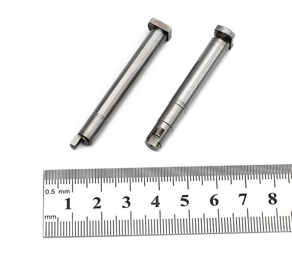
(Board to board, FPC,RF mold parts)
- ISO 9001:2015–oriented process & documented inspection paths
- Zeiss / Nikon class metrology available for critical dimensions
- DFM feedback from 10+ senior tooling engineers
- Dongguan HQ + Quanzhou capacity for volume programs
Board to board, FPC,RF mold parts
High-Precision Board to Board, FPC, RF Mold Parts for Advanced Electronics
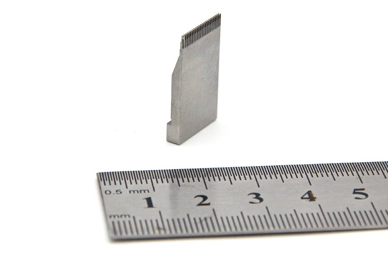
As electronic devices become smaller, faster and more integrated, the demand on interconnect components increases dramatically. Board to board, FPC, RF mold parts are specialized precision components designed to support modern connector systems that link printed circuit boards, flexible printed circuits (FPC) and RF modules in a compact, high-density environment.
These mold parts typically include the molded housings, insulators, guides and structural elements used in board-to-board mezzanine connectors, FPC/FFC connectors and RF coaxial or board-to-FPC RF interfaces. By providing accurate positioning, insulation and mechanical reinforcement, they help maintain stable electrical performance, reduce assembly errors and increase the reliability of the final product.
Whether you are developing consumer electronics, industrial control equipment, automotive modules or RF communication devices, high-quality mold parts form the backbone of a durable connector system.
Key Features & Benefits
Engineered around the demanding requirements of PCB and FPC connectivity, these mold parts deliver several practical advantages for design engineers and manufacturing teams.
- Precise alignment for board-to-board connectors – Molded housings and guides support accurate stacking height and pitch alignment between two PCBs, reducing signal skew and mechanical stress during mating and unmating.
- Optimized for FPC / flexible circuit interfaces – Mold parts are shaped to support thin, flexible printed circuits, protecting the FPC tail, maintaining contact pressure and helping to minimize bending stress at the termination point.
- RF-optimized structures – RF mold components are designed to support connectors in high-frequency paths, with geometries that help maintain controlled impedance, minimize leakage and reduce unwanted coupling in sensitive RF sections.
- High dimensional accuracy – Precision tooling and molding processes ensure consistent cavity dimensions, wall thickness and contact positioning, which is critical for fine-pitch connectors and high-pin-count arrays.
- Robust mechanical support – Mold parts reinforce solder joints and contacts against vibration, shock and repeated mating cycles, extending the operational life of the connector and reducing field failures.
- Material options for demanding environments – Connector mold parts can be produced from engineering plastics suited to elevated temperatures, reflow soldering processes and harsh operating conditions, depending on your project requirements.
- Customization-ready – Geometry, keying features, polarization, mounting flanges and locking structures can be tailored to match unique board layouts and mechanical envelopes, supporting OEM-specific connector designs.
Specifications & Core Attributes
Use the table below as a reference overview of typical capabilities and design options for board to board, FPC and RF mold parts. Exact specifications will vary by connector series and project requirements.
| Attribute | Description |
|---|---|
| Product scope | Molded housings, insulators, guides and structural parts for board-to-board, FPC/FFC and RF connectors |
| Typical applications | Consumer electronics, industrial control, automotive electronics, communication modules, IoT devices, RF front-end boards |
| Supported connector types | Mezzanine board-to-board, stacker connectors, FPC/FFC ZIF and non-ZIF, board-to-FPC RF interfaces, RF coaxial board jacks |
| Pitch compatibility | Suited for fine-pitch and standard-pitch layouts; exact pitch determined by matching connector design |
| Material options | Engineering thermoplastics formulated for electrical insulation, dimensional stability and soldering heat resistance |
| Thermal performance | Designed for compatibility with standard SMT reflow and wave soldering processes; high-temperature grades available |
| Color / visual coding | Neutral and application-specific colors available to support assembly identification and polarization |
| Mounting options | Surface-mount compatible profiles, through-hole retention features and mechanical locking structures depending on connector system |
| RF-specific considerations | Mold geometries can support controlled impedance, shielding features and defined ground paths for RF connectors |
| Customization | Custom cavity design, keying, branding and special mounting flanges offered to align with OEM connector requirements |
Typical Use Cases & Ideal Customers
Board to board, FPC and RF mold parts are widely used wherever compact electronics require reliable internal connections. They are particularly valuable when products must balance small form factors with robust electrical performance.
- OEM product designers – Ideal for design teams creating smartphones, tablets, wearables, medical devices, industrial controllers or vehicle ECUs where space savings and connection reliability are critical.
- EMS and contract manufacturers – Provide consistent, easy-to-handle connector components that reduce assembly variability, support automated pick-and-place and improve yield on fine-pitch PCBs and FPC assemblies.
- RF and wireless module developers – RF mold parts support stable, low-loss connections between RF front-end boards, antennas and main logic boards, especially where board-to-FPC RF transitions are required.
- Prototyping and small-batch projects – Enable engineers to validate mechanical envelopes, stacking heights and FPC routing concepts before committing to mass production tooling.
- High-vibration or harsh environments – Automotive, industrial and transportation applications benefit from reinforced connector housing designs that protect against vibration, shock and thermal cycling.
Through careful selection of connector styles and corresponding mold parts, engineers can optimize signal paths, simplify layout routing and improve the long-term durability of finished devices.
Selection, Care & Buying Guidance
Choosing the right mold parts for board to board, FPC and RF connectors begins with understanding the electrical, mechanical and manufacturing requirements of your project.
- Match the connector system – Always select mold parts that are specifically designed for the connector series you are using. Pay attention to pitch, stacking height, number of positions and mating orientation.
- Check PCB and FPC constraints – Review board thickness, pad geometry, FPC stiffness and bend radius. Adequate mechanical support from the mold housing helps prevent cracking or peeling at solder joints.
- Consider RF and signal integrity – For RF sections and high-speed digital lines, ensure that the mold design supports stable impedance and minimizes discontinuities and crosstalk.
- Plan for manufacturing – Confirm compatibility with your assembly process, including SMT reflow profiles, cleaning processes and inspection methods. Mold parts should allow reliable pick-and-place and visual inspection.
- Evaluate environmental requirements – If the device will experience high temperature, humidity, vibration or contaminants, choose material grades and connector families rated for those conditions.
Proper handling and storage also contribute to connector reliability. Keep mold parts in their original packaging until use, avoid excessive mechanical stress, and follow the connector manufacturer’s recommended assembly sequence to prevent damage.
FAQ
Are these mold parts compatible with my existing board-to-board connectors?
Compatibility depends on the specific connector series and pitch used in your design. In most cases, mold parts are tailored to a particular connector family, so you should match them to the exact series and configuration specified in your PCB layout and bill of materials.
Can I use these components with flexible printed circuits (FPC) of different thicknesses?
Many FPC connector systems support a defined range of FPC thicknesses. When selecting mold parts for FPC connectors, verify the supported thickness range and ensure your FPC stack-up fits within the connector manufacturer’s guidelines to maintain proper clamping force and contact reliability.
What should I consider for RF applications using these mold parts?
For RF use, focus on connectors and mold parts that support controlled impedance, minimal gap variation and stable mechanical alignment. Follow recommended PCB footprint and ground pattern layouts, and avoid introducing unnecessary discontinuities in the RF path near the connector.
How are these components packed and shipped?
Mold parts and associated connectors are typically supplied in protective packaging such as reels, trays or tubes that support automated assembly and prevent mechanical damage. Check product documentation for the exact packing style and quantity per reel or tray.
Do I need any special tools to assemble board-to-board and FPC connectors with these mold parts?
Most SMT-compatible connectors using these mold parts can be assembled using standard pick-and-place equipment and reflow soldering processes. If the connector includes latches or locking mechanisms, basic hand tools may be used during final mating and cable insertion.
How should I store the mold parts before assembly?
Store the parts in a clean, dry environment, away from direct sunlight and excessive heat. Keep them in their original sealed packaging until use to prevent contamination and mechanical damage, and follow any shelf-life or storage recommendations provided with the components.
Can these mold parts be customized for a unique connector design?
Yes. Many manufacturers support customization such as modified housing geometry, special keying, branding and application-specific mounting features. Provide your mechanical drawings and performance requirements to discuss feasibility and tooling options.
What is the typical warranty or return policy for these components?
Warranty and returns depend on the supplier’s terms and conditions. Generally, unopened and unused parts can be returned within a defined period if they do not meet the agreed specifications. For detailed warranty coverage, consult the sales contract or supplier documentation.
How can I verify the quality of the mold parts upon receipt?
Inspect the packaging for damage, check part numbers and lot codes, and perform visual inspection under magnification to confirm that cavities, walls and alignment features are free from defects. For critical applications, you may also carry out fit tests on sample connectors and boards.
Are these mold parts suitable for high-volume automated production?
Yes, the parts are designed with consistent geometry and packaging options that support high-volume automated placement and soldering. Ensure your process parameters, such as pick-up nozzle design and reflow profile, are tuned to the specific connector family and mold material.
Same drawing, predictable results—next batch
Share revision, quantity ramp, and inspection level. We quote process route, ship date, and documentation in one structured response.