
Plastic film parts · Precision mold insert
Board to Board, FPC, RF Mold Parts – Precision RF Connector & Molded Component Set Board to board, FPC,RF mold parts
Brand Xuxiang Mold
Availability Made to drawing
RFQ pricing
Quote from STEP / PDF & quantity
Engineered for modern compact electronics, this integrated set of Board to board, FPC, RF mold parts delivers reliable high‑frequency signal transmission in tight spaces. Designed for OEMs, EMS providers, and RF module developers, it combines precision connector interfaces with custom RF‑friendly molded parts to simplify layout and assembly. Enjoy stable impedance control, robust mechanical retention, and space‑saving profiles for handheld, IoT, automotive, and industrial devices. Each component is manufactured with high‑precision tooling to ensure long service life and consistent performance. From prototype to mass production, this solution helps shorten your design cycle while improving overall product reliability.
(Board to board, FPC,RF mold parts)
- ISO 9001:2015–oriented process & documented inspection paths
- Zeiss / Nikon class metrology available for critical dimensions
- DFM feedback from 10+ senior tooling engineers
- Dongguan HQ + Quanzhou capacity for volume programs
Board to board, FPC,RF mold parts
Overview: What Are Board to Board, FPC, RF Mold Parts?
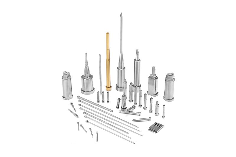
The Board to board, FPC, RF mold parts offering is a comprehensive interconnect and mechanical solution designed for electronic products that require high‑density, high‑frequency, and space‑constrained connections. It typically combines three core elements:
- Board‑to‑board connectors for rigid PCB‑to‑PCB stacking and mezzanine connections.
- FPC (Flexible Printed Circuit) connectors for connecting thin, bendable flex cables to rigid PCBs in narrow or moving spaces.
- RF mold parts, including precision molded housings, shields, and support structures that stabilize RF connectors, protect signal integrity, and simplify assembly.
This product concept is tailored for manufacturers who need to integrate RF modules, antennas, and high‑speed digital signals into compact devices such as smartphones, wearables, routers, IoT terminals, automotive control units, industrial sensors, and more. By combining electrical connectors with RF‑optimized molded parts, it helps ensure both reliable signal transmission and mechanical robustness throughout the product lifetime.
Key Features & Benefits
Choosing the right combination of board‑to‑board, FPC, and RF mold parts can have a major impact on device performance, ease of assembly, and long‑term reliability. This solution is designed around several key benefits:
- High‑density interconnects
Compact board‑to‑board and FPC connector geometries support tight stacking heights and small footprints, ideal for portable and miniaturized designs where every millimeter counts. - Optimized for RF performance
RF mold parts are shaped and arranged to support controlled impedance routing, stable connector positioning, and effective shielding of sensitive RF paths, helping to minimize insertion loss, crosstalk, and EMI. - Mechanical stability and strain relief
The molded components reinforce thin FPC tails, delicate RF connectors, and tall board stacks, reducing stress on solder joints and pads in environments subject to vibration, shock, or repeated handling. - Design flexibility
A modular approach allows you to combine various stacking heights, orientations, and FPC pitches with different molded housings or fixtures, so the final configuration can match your board layout and enclosure constraints. - Assembly efficiency
Well‑designed RF mold parts act as positioning guides, connector nests, or integrated shields, making it easier for operators or automated equipment to align, insert, and solder the interconnects, thus reducing assembly time and rework. - Improved product reliability
By maintaining consistent connector alignment, protecting against mechanical stress, and providing stable RF grounding, this combined solution helps reduce field failures and supports long‑term performance in demanding applications.
Specifications & Key Attributes
Because board‑to‑board, FPC, and RF mold parts are typically configured to match a specific project, exact numerical specifications vary by design. The table below summarizes the typical characteristics and options you can expect from this type of solution.
| Attribute | Description |
|---|---|
| Connector Types | Board‑to‑board mezzanine connectors, FPC/FFC connectors, RF coaxial or RF board‑to‑board interfaces |
| Typical Applications | Mobile devices, IoT modules, RF front‑ends, routers, automotive ECUs, industrial control, consumer electronics |
| Mounting Style | Surface‑mount (SMT) on rigid PCBs with mating FPC or opposing PCB; RF mold parts typically assembled to PCB or chassis |
| Stacking / Profile Options | Low‑profile board‑to‑board heights and slim FPC entries designed for compact enclosures |
| FPC Support | Horizontal or vertical FPC insertion, top or bottom contact styles, with molded strain‑relief features where required |
| RF Mold Materials | Engineering plastics suitable for RF environments, selected for dimensional stability, heat resistance, and dielectric properties |
| Shielding & Grounding | Options for integrating metal shields, ground springs, or molded features that interface with device ground planes |
| Operating Environment | Configurations available to suit consumer, industrial, or automotive conditions, depending on project requirements |
| Customization | Custom mold tooling, connector arrangements, keying features, and marking available for OEM projects |
| Compliance & Testing | Designed to meet typical industry expectations for reliability, contact durability, and environmental stress (exact standards depend on chosen components) |
Use Cases & Who This Is For
This combined Board to board, FPC, RF mold parts solution is best suited for engineering teams and buyers working on:
- RF‑enabled consumer electronics
Smartphones, tablets, smartwatches, wireless earbuds, and other portable devices using integrated antennas, Wi‑Fi, Bluetooth, cellular, or GNSS modules that need stable RF connections in very small spaces. - IoT and communication modules
Compact gateways, sensor nodes, NB‑IoT or LTE‑M modules, and Wi‑Fi/BLE modules that rely on precise board‑to‑board and FPC routing between RF front‑ends and baseband processors. - Automotive electronics
Telematics units, ADAS modules, infotainment systems, and keyless entry antennas where high reliability, vibration resistance, and RF performance are essential. - Industrial and medical devices
Measurement equipment, portable test instruments, medical handhelds, and diagnostic systems that combine high‑speed digital and RF signal paths inside compact housings. - Networking & infrastructure
Small cells, routers, access points, and RF front‑end subsystems that must fit into dense boards while maintaining consistent RF performance over temperature and time.
It is ideal for:
- OEM hardware teams seeking a coordinated approach to connectors and mechanical RF support.
- EMS/ODM manufacturers responsible for both design optimization and mass‑production assembly.
- Purchasing professionals consolidating multiple connector and molded‑part sources into one integrated package.
Selection & Buying Guidance
When specifying a Board to board, FPC, RF mold parts solution for your project, consider the following factors to ensure the final design meets your electrical, mechanical, and cost targets:
- Signal requirements
Identify the RF bands, data rates, and signal types to be carried across the interconnects. Higher‑frequency RF and very high‑speed digital lines will benefit from shorter paths, controlled impedance, and well‑designed shielding using RF mold parts. - Mechanical envelope
Measure the available space, stacking height, and orientation constraints in your enclosure. This will drive connector pitch, profile, and FPC routing as well as the geometry of the molded supports and shields. - Environmental conditions
Consider operating temperature, vibration, shock, and exposure to contaminants. Automotive and industrial designs may require more robust connectors and mold materials with higher temperature and chemical resistance. - Assembly process
Review whether your production line uses manual insertion, semi‑automatic fixtures, or full SMT automation. Mold parts can be tailored with alignment features and pick‑and‑place‑friendly shapes to improve throughput and reduce errors. - Lifecycle and serviceability
Determine whether connectors must be cycled or re‑mated in the field, or if they are intended for permanent assembly. This will influence the choice of connector contact structure, retention force, and mechanical reinforcement within the molded parts. - Customization vs. standardization
Standard connectors can shorten lead times and simplify replacement, while custom RF mold parts and tailored layouts can maximize performance and save space. Balancing these factors early in the design phase helps control both BOM cost and tooling investment.
Working closely with your supplier on samples, 3D models, and layout guidelines will further help you optimize pad design, keep‑out zones, and RF trace routing around the connectors and mold structures.
FAQ
Are these Board to board, FPC, RF mold parts compatible with my existing PCB design?
Compatibility depends on your board layout, pitch, stacking height, and RF path requirements. In most cases, your PCB can be adapted to use standard connector footprints while customizing the RF mold parts to fit your mechanical envelope. Sharing your schematic, stack‑up, and mechanical drawings with the supplier will help confirm compatibility.
How do I choose the right stacking height and FPC orientation?
Start from your mechanical constraints: the distance between boards, the direction of FPC bending, and any interference with enclosures or shields. Then select board‑to‑board connectors or FPC connectors whose profile and entry direction match these constraints. Your supplier can recommend a combination of heights and orientations based on your 3D model.
What should I consider for RF performance when using these parts?
For best RF performance, keep RF paths as short as practical, maintain consistent impedance, and avoid unnecessary transitions. RF mold parts can integrate or support shielding structures and ensure accurate connector positioning so that ground connections remain stable. Work with RF layout guidelines that define trace width, spacing, and ground via placement near the connectors.
How are the RF mold parts installed during assembly?
RF mold parts are typically installed either by press‑fitting onto the PCB, snapping into cut‑outs, or being secured with screws or adhesive, depending on the design. Many designs use features that allow the mold parts to act as positioning jigs for the connectors, simplifying alignment for both manual and automated assembly.
What are the shipping and lead time options for these components?
Standard connectors generally ship on reels or trays with lead times depending on stock levels, while custom RF mold parts may require tooling and sampling before mass production. Discuss your forecast volumes and project schedule with the supplier to align on realistic lead times and logistics options.
Can these connectors and molded parts handle automotive or industrial environments?
Yes, with appropriate material and connector choices, the solution can be configured for automotive or industrial use. This typically involves selecting higher‑temperature plastics, more robust plating, and reinforced mechanical structures. Clarifying your target environment and qualification requirements at the start of the project is important.
How should I care for and handle FPC and RF connectors during assembly?
Handle FPC and RF connectors with ESD protection and avoid touching contact surfaces directly. Do not exceed the specified insertion and extraction forces, and ensure that FPC tails are inserted straight into the connector slot. Using RF mold parts to guide and support the connectors helps prevent damage from misalignment or excessive bending.
What is the typical warranty or return policy for these parts?
Warranty terms vary by supplier, but components are usually covered against manufacturing defects for a defined period. Returns are generally accepted for unused, undamaged parts within an agreed timeframe. For custom RF mold parts and connector configurations, policies may focus on pre‑production validation to minimize issues during mass production.
Can I request customization of only the RF mold parts while using standard connectors?
Yes, many projects combine standard, off‑the‑shelf board‑to‑board and FPC connectors with customized RF mold parts. This approach helps control cost and lead time while still giving you mechanical features tuned to your specific enclosure and assembly process.
Do you provide design support for integrating these parts into new products?
Most suppliers offer engineering support such as 2D/3D models, recommended land patterns, and layout guidance. For complex RF designs, they may also review your PCB stack‑up and antenna placement to help you get the most from the Board to board, FPC, RF mold parts solution.
Same drawing, predictable results—next batch
Share revision, quantity ramp, and inspection level. We quote process route, ship date, and documentation in one structured response.