
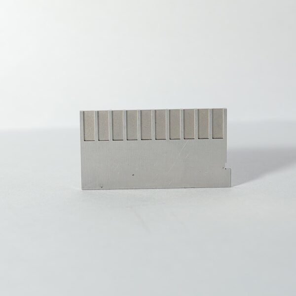
Plastic film parts · Precision mold insert
Precision Mold Components for Automotive Connectors – Fine-Pitch Tooling Parts Set
Brand Xuxiang Mold
Availability Made to drawing
RFQ pricing
Quote from STEP / PDF & quantity
Engineer repeatable, high-yield production of complex plug and socket housings with these precision mold components for automotive connectors. Each core, sleeve and insert is ground to tight tolerances to support fine-pitch terminals and miniature cavity layouts. Optimized gating and cooling interfaces help you achieve stable cycle times while maintaining dimensional consistency across high-volume runs. Designed for modern automotive electrical architectures, these tooling parts support multi-cavity connector molds and accelerated project turnaround. Ideal for OEMs and tier suppliers looking to improve connector quality, uptime and tooling life.
- ISO 9001:2015–oriented process & documented inspection paths
- Zeiss / Nikon class metrology available for critical dimensions
- DFM feedback from 10+ senior tooling engineers
- Dongguan HQ + Quanzhou capacity for volume programs
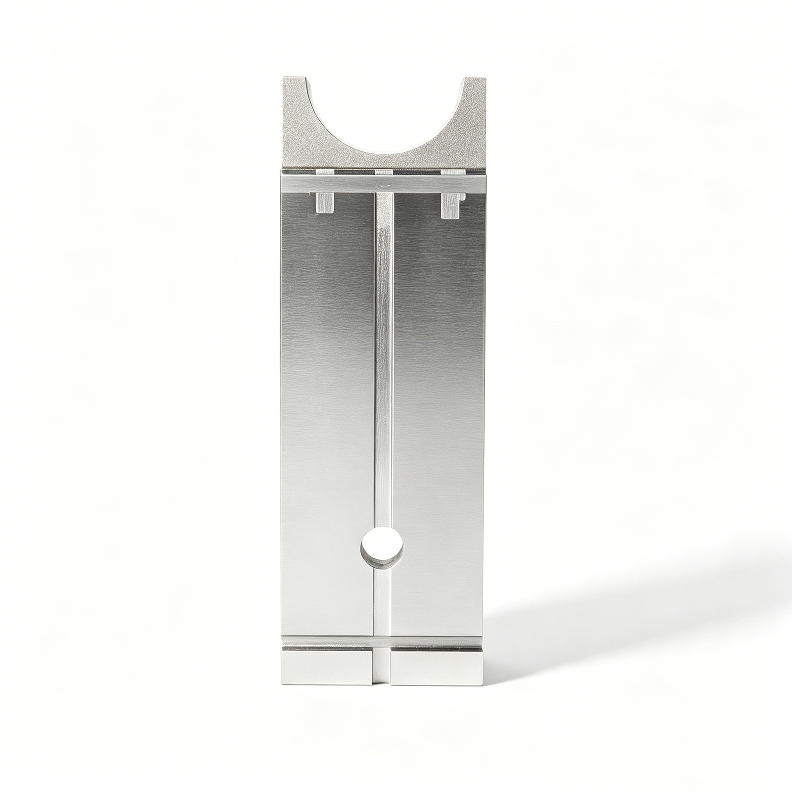
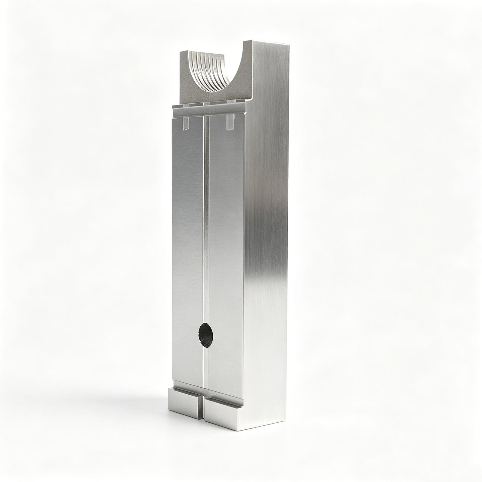
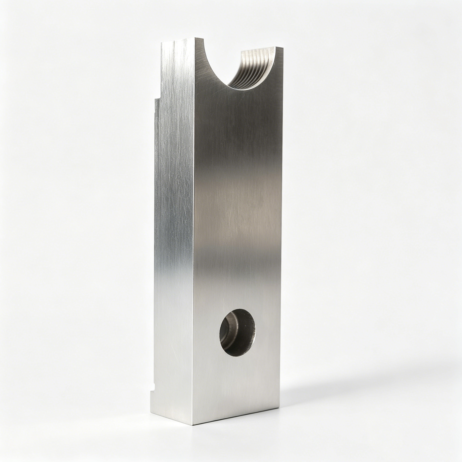
Fine-Pitch Precision Mold Components for Automotive Connectors
These precision mold components for automotive connectors are engineered for toolmakers and automotive suppliers who need reliable, dimensionally stable tooling for modern electrical connector programs. From compact sensor plugs to multi-pin ECU connectors, the components support high-cavitation molds where even a micron-level deviation can lead to poor mating, electrical failure or costly rework.
Built around proven connector mold design principles, the set typically includes core inserts, cavity blocks, sleeves, gate inserts, ejector elements and alignment parts tailored to your connector geometry and plastic grade. Careful control of tolerances, surface finish and material selection helps you manage shrinkage, warpage and flash while keeping cycle times competitive in demanding automotive environments.
Key Features & Performance Benefits
Every element in this tooling set is specified for the realities of automotive connector production, where requirements for repeatability, insulation performance and robust assembly are stringent.
- Fine-pitch ready: Designed to support narrow terminal spacing, thin walls and miniature locking features commonly found in modern automotive plug and socket housings.
- Dimensional accuracy for secure mating: Precision cavity and core geometry helps ensure connector halves align properly with mating components and terminal blocks, reducing insertion force issues and misfit-related failures.
- Stable during high-volume runs: Good heat treatment practice and stable steel selection help resist deformation and wear under continuous injection cycles, supporting long service life and consistent part dimensions.
- Optimized for connector flow and cooling: Component geometries and interface surfaces are laid out to work with balanced runner, gate and cooling designs so that plastic flow, packing and cooling are more uniform across the cavity.
- Smooth demolding: Carefully defined draft angles and surface finishes work together with ejector elements to release delicate connector features without stress whitening, cracking or gate blush.
- Adaptable to different connector families: Suitable for various connector styles including blade-type, round-pin, sealed harness connectors, sensor plugs and in-line couplers used throughout the vehicle.
Specifications & Core Attributes
The exact configuration is customized to your program, but the table below summarizes typical attributes and options considered when defining a mold component set for connector tooling.
| Attribute | Description |
|---|---|
| Application | Injection mold tooling for automotive electrical connector housings and related plastic parts |
| Component types | Core inserts, cavity blocks, sleeves, guide elements, gate inserts, ejector elements, support plates as specified |
| Typical materials | Tool steels or stainless steels selected for wear resistance, polishability and dimensional stability under thermal cycling |
| Tolerance strategy | Fine-tolerance machining and grinding on critical connector features to support reliable mating and terminal position |
| Surface finish | Polished or textured in line with connector functional zones, from high-gloss contacts areas to controlled texture grips |
| Connector styles supported | Inline, header, sensor, sealed harness, multi-row ECU and other common automotive connector families |
| Molding materials | Compatible with typical automotive connector resins such as high-performance, heat-resistant, non-conductive plastics |
| Mold design compatibility | Can be integrated into single-cavity or multi-cavity molds; supports cold runner or hot runner layouts according to project |
| Customization | Dimensions, interface points and feature details configurable to your connector drawings, GD&T requirements and molding equipment |
| Quality focus | Supports high dimensional accuracy to help minimize flash, short shots, warpage and gate-related defects in final connectors |
Typical Use Cases & Who It’s For
These mold components are intended for organizations responsible for launching and maintaining automotive connector programs where uptime and part quality are critical.
- Automotive OEMs and tier suppliers: Ideal for in-house toolrooms and qualified tooling partners producing connectors for body electronics, powertrain, safety systems, lighting and infotainment.
- Precision mold makers: A solid basis for building new automotive connector molds or refurbishing existing tools that must meet tighter tolerance or new platform requirements.
- Engineering and R&D teams: Useful for pilot tools, prototype molds or bridge tooling when validating new connector designs, material changes or updated terminal layouts.
- High-mix connector production: Suits plants running multiple connector families that demand fast changeover and consistent cavity performance over extended production campaigns.
By deploying components tailored to connector geometry and process parameters, you can reduce troubleshooting time, accelerate PPAP and maintain capability indices in line with automotive quality expectations.
Care, Maintenance & Purchasing Guidance
To safeguard tool investment and connector quality, it is important to maintain the mold components systematically and specify them correctly at purchase.
- Routine inspection: Regularly check critical core and cavity surfaces for wear, micro-cracks or buildup, especially in gating areas and around thin walls or locking features.
- Cleaning practices: Use appropriate mold cleaners and non-abrasive tools to remove resin residue and vent deposits without damaging precision surfaces or edges.
- Lubrication and storage: Apply suitable rust preventives and lubricants on moving components and store inserts in a controlled environment to prevent corrosion and dimensional change between runs.
- Replacement planning: Track cavity counts and connector defect trends to anticipate when certain components should be reworked, polished or replaced to maintain capability.
- Specifying new components: When ordering, provide connector drawings, 3D models, material details and any special tolerance zones so that critical areas can be prioritized in design and machining.
Thoughtful selection and care of these components help keep molds running reliably, support stable cycle times and ensure that the connectors leaving your plant meet both internal and customer-specific requirements.
FAQ
Are these mold components compatible with my existing connector mold base?
In most projects, components can be manufactured to match your current mold base dimensions, guide systems and mounting patterns. Share your existing tool drawings so interfaces can be aligned and any necessary transition plates or adaptors can be defined before production.
Which types of automotive connectors can these components be used for?
The components can be tailored for a wide range of connector styles, including sealed harness connectors, multi-row ECU connectors, sensor plugs and in-line couplers. As long as the connector is injection molded, the tooling can be configured around its geometry and resin choice.
What information do I need to provide to specify the components correctly?
You should prepare current 2D drawings or 3D models of the connector, any functional dimension or GD&T requirements, target resin data and your molding equipment details. This information allows the component design to account for shrinkage, draft, gating and demolding requirements specific to your application.
How do I maintain the precision of fine-pitch core and cavity areas over long runs?
Follow a preventive maintenance schedule that includes cleaning vents and gates, inspecting thin sections for wear, and re-polishing or reworking key surfaces before dimensional drift affects part quality. Proper temperature control and avoiding aggressive cleaning tools also help preserve precision geometry.
Can these components handle high-temperature, high-performance connector resins?
Yes, component materials and treatments can be selected to work with higher-temperature, abrasion-resistant resins often used in engine bay or power electronics connectors. It is important to share the resin grade so that suitability for operating temperature and wear resistance can be considered in advance.
What is the typical lead time for customized mold components?
Lead time depends on complexity, number of cavities and validation needs. Simple replacement inserts are generally faster to produce than full multi-cavity sets. Providing complete technical information early in the process shortens design iterations and overall delivery time.
How do I know if my connector design needs special gating or cooling features?
Signs include challenging wall thickness transitions, long flow lengths, tight flatness requirements or frequent warpage and short-shot issues in existing tools. In such cases, gating and cooling layouts should be reviewed during component design so that the new parts support more uniform fill and cooling.
What is the recommended way to store spare inserts and pins between production runs?
Store components in labeled, protective cases in a clean, dry environment. Apply a light rust preventative on susceptible surfaces and avoid stacking parts where edges or precision faces may contact each other. Documenting where each insert belongs in the mold speeds up reassembly for the next run.
What happens if a component wears out or gets damaged during production?
If damage is localized, it may be possible to rework or polish the area within tolerance; otherwise, the component should be replaced using the original specifications or CAD data. Keeping a record of component drawings and previous revisions allows fast reproduction and minimizes downtime.
Is there any special care required during installation into the mold?
Ensure that all seating surfaces are clean, burr-free and free from contamination before installation. Components should be fitted according to the specified alignment scheme and tightened to recommended torque levels. After assembly, a trial molding run and dimensional check of sample connectors are advisable before full-scale production.
Related products
Same drawing, predictable results—next batch
Share revision, quantity ramp, and inspection level. We quote process route, ship date, and documentation in one structured response.