
Industries · Aerospace & electronics connector molding
Connector-Adjacent Molding Where Tolerances, ESD Notes, and Flash Risk Meet Reality
Aerospace and electronics connector molding fails incoming when pocket depth, parting-line flash, and insulator warp were never tied to the mating shell and contact system. Xuxiang quotes connector programs with tight tolerances discussed against measurable surfaces, plus honest boundaries for ESD, cleanliness, and what your electrical validation owns downstream.
For general production thermoplastics, see injection molded plastic components. For regulated or multi-material lanes, use the dedicated service pages or Contact with one consolidated RFQ.
What we align before sampling hardens
- Which dimensions are true assembly gates versus documentation-only
- Resin grade, fillers, and any ESD or outgassing language in your spec
- How you plan to prove retention, mate force, or continuity after molding

Connector Geometry Is a Stack-Up Problem, Not a Solo Plastic Part
Pockets · ribs · draft · parting-line flash
Tight connector insulators and housings argue with reality when CAD assumes perfect mates. We surface assumptions about draft on latch features, rib-to-pocket stiffness, and where flash is unacceptable because it changes dielectric standoff or latch travel.
- Which faces must stay burr-free for mating or sealing?
- Where is knit-line risk incompatible with your electrical spacing story?
- What gage or pin checks will receiving actually run?
Procurement note
If a quote cannot point to the assumed parting line and flash control plan, you are not comparing molders—you are comparing optimism. Ask for the gate family and how it protects your worst-case pocket.
Kickoff checklist
- 3D + 2D with revision, units, and datums tied to assembly function
- Mating metal drawings or STEP references for critical interfaces
- Material callouts, UL context, and ESD or cleanliness requirements
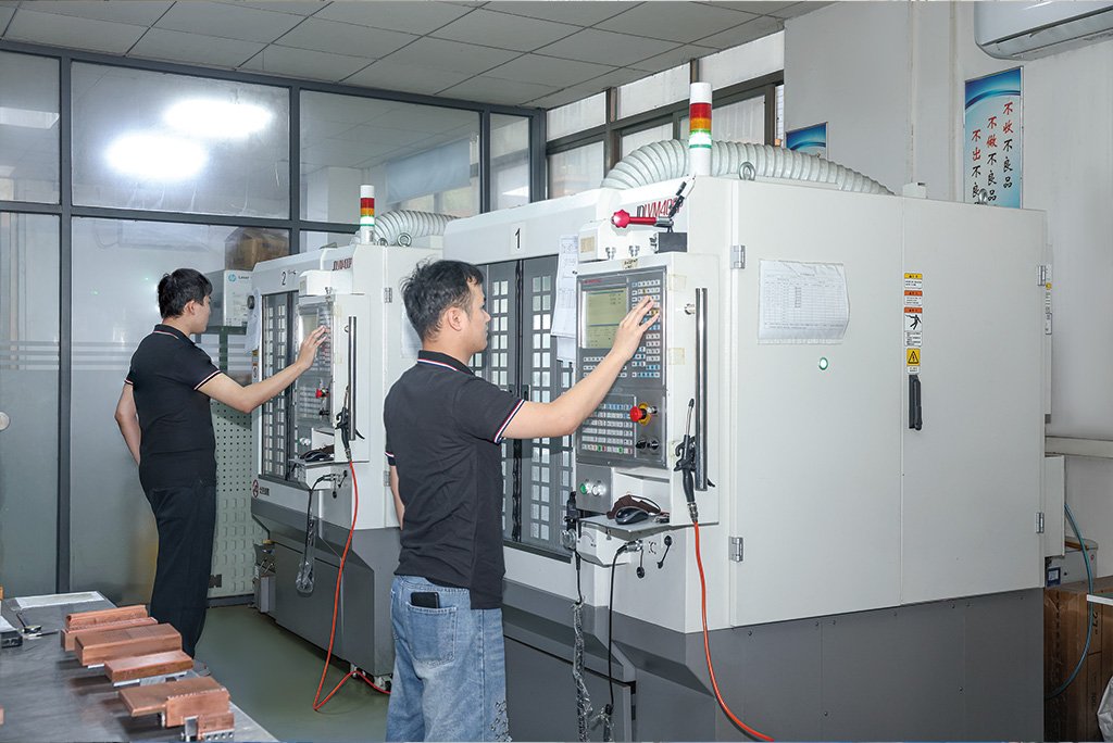
Typical Scope for Aerospace & Electronics Connector Molding
Insulators · backshell-adjacent housings · avionics-style hardware (as released)
Envelope is always confirmed in quote, but teams often start here for connector-adjacent molded features:
High-performance insulators and bodies
Pockets, towers, and latch features where draft, sink, and warp interact with mate force and continuity checks.
Shell-adjacent plastics
Housings and guides where parting-line flash risk must stay below your sealing or EMI strategy assumptions.
Avionics and industrial electronics contexts
Programs where documentation discipline and revision control matter as much as cavity count.
Secondary operations (when explicitly released)
Laser mark, light machining, or controlled assembly—not silent add-ons.
Wrong lane?
If the program is fundamentally multi-shot or soft-touch dominated, start with multi-shot & 2K molding—send one package and we will recommend the lane.
Material Discipline: ESD, Cleanliness, and “Equivalent Resin” Rules
Conductive fillers · carbon tracking · handling boundaries
ESD-safe molding is not a sticker on a box—it is a chain of resin assumptions, moisture sensitivity, pigment interactions, and what happens at the machine and pack-out. We document what we can control in molding versus what belongs to your ESD program downstream.
- Approved lists, regrind policy, and pigment restrictions that affect surface resistivity
- Packaging expectations when connectors cannot tolerate dust or fiber contamination
- Explicit sign-off before any “equivalent” grade that touches UL or outgassing context
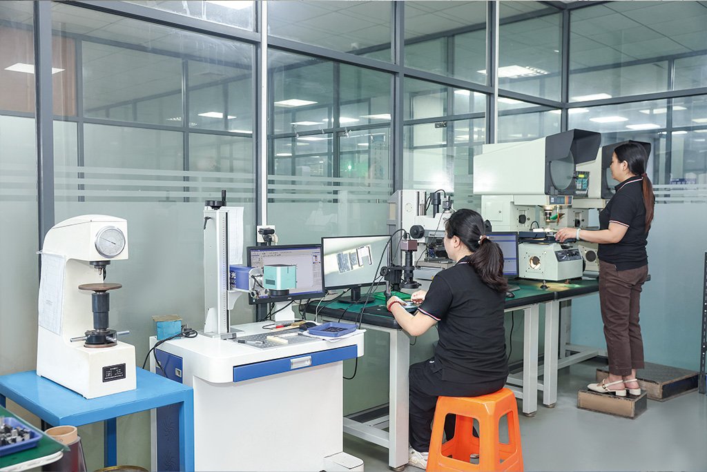
Inspection Plans Matched to Connector Risk, Not Generic Layouts
CMM · vision · functional gages · electrical test boundaries
Connector molding arguments often land on datums that flex during measurement. We align layouts to measurable surfaces, agreed sampling, and the same characteristics your receiving team rejects—especially when a pocket is tight but the true failure mode is mate stack-up.
- Balloon maps welcomed early so molding and metrology stay parallel
- Notes when a dimension is better validated with assembly context or gage pins
- Clear statement of what electrical tests are customer-owned versus in-scope at Xuxiang
Schedule realism
- Texture and coating cycles can reorder cosmetic buy-off—surface early
- Tool steel lead times may justify staged cavity releases when agreed
- Engineering changes after texture approval carry different risk—call them out
Resins, Additives, and Environmental Assumptions for Connectors
High-temp grades · flame context · chemical exposure · color stability
What we commonly support
Engineering thermoplastics selected for dimensional stability, dielectric behavior, and chemical exposure notes—especially when tight pockets must survive reflow-adjacent or harsh environments as your drawing states.
What to include in the RFQ
Approved material lists, equivalent rules, regrind policy, ESD targets, and any restrictions on pigments or lubricants that affect surface chemistry or tracking resistance.


Certifications & quality systems
Documentation that supports OEM vendor files
Aerospace and electronics connector molding still has to pass your quality gate. We operate under recognized management system frameworks and can bundle material traceability and dimensional reporting when your PO requires it. Certificate scope and registration particulars are supplied for vendor files on request.
ISO 9001:2015
Documented control of processes, changes, and corrective actions—so connector programs and tooling revisions do not drift between lots.
ISO 14001:2015
Environmental management practices aligned to manufacturing realities, waste handling, and continuous improvement.
ISO 45001:2018
Occupational health and safety management supporting disciplined shop-floor routines alongside precision molding production.
Material records
Certificates and traceability released against revision-controlled part data when your program demands it.
Inspection discipline
Layout plans tied to named critical characteristics—agreed in quote so reports match your FAIR or internal template.
Ask for the certificate package or customer-specific quality addendum in your RFQ—we route it with the same technical owner.
What customers say
Field notes from connector and avionics-adjacent programs
Representative feedback from buyers who care about stack-up honesty and inspection alignment. Swipe on mobile or use the arrows.
How to RFQ Aerospace & Electronics Connector Molding
Faster quotes · fewer hidden stack-up assumptions
- 3D + 2D with revision, units, and true assembly-critical dimensions
- Mating metal references, retention targets, and any mate-force or continuity validation plan
- Resin targets, UL context, ESD requirements, and approved equivalent rules
- Flash sensitivity notes at parting lines and cosmetic bands on connector faces
- Inspection template, balloon map, or customer gate language when you have it
Photos of prior failures (flash, warp, contamination) help us align gate and handling risk before steel hardens.
What speeds a grounded connector response
- Pin gage sizes, go/no-go intent, and which pockets are electrical spacing critical
- Environmental assumptions: temperature swing, chemical exposure, and vibration context
- Packaging and cleanliness expectations at ship point
Share customer templates early so evidence matches your gate.
Xuxiang Manufacturing Services
Internal links · same structure as the site menu
This page focuses on aerospace and electronics connector molding—alongside tooling, machining, and specialty molding lanes. Use the manufacturing services hub or jump to a landing page below.
Mold tooling & components
Cavity steel, plates, and standards—see dedicated mold landing pages.
Machining
CNC, Swiss, and general precision metal removal.
Injection molding & parts
Molded plastics—not cavity steel—for part & program RFQs.
Industries
Application-led molding discovery.
- Aerospace & electronics connector molding You are here
OEM metal parts
BOM-level machined metal for industrial equipment.
Quality & export
Documentation, ISO language, and overseas buyer support.
Why Teams Choose Xuxiang for Aerospace & Electronics Connector Molding
We treat connector molding as an interface program: plastic features, metal mates, ESD context, and inspection evidence are discussed with the same characteristics your receiving team enforces.
Invitation
Send part data with revisions and the top five risks (flash, pocket depth, knit proximity, warp, contamination). We will return scope you can compare fairly: tooling strategy, sampling plan, and evidence—not a blind cavity price.
- Stack-up honesty: mates and gages named before steel freezes
- Material clarity: ESD and equivalent rules documented, not implied
- Lane honesty: multi-shot or regulated lanes recommended when the program demands it
xuxiangmold.com · Dongguan Xu Xiang Precision Mold Co., Ltd.
Frequently Asked Questions (FAQ)
Common questions about aerospace and electronics connector molding, scope, and how we work with OEM buyers.
Q:Do you mold aerospace and electronics connector style parts with tight tolerances?
A: Yes—when drawings name true assembly-critical dimensions, material grade or approved list, ESD or cleanliness notes, and how you plan to validate mates and retention in the connector stack-up.
Q:What should an RFQ include for connector molding programs?
A: 3D plus 2D with revision, mating component references, pin or pocket tolerances, flash sensitivity at parting lines, resin targets with equivalent rules, and any inspection template you want evidence to match.
Q:How do you handle ESD and contamination expectations?
A: We document resin assumptions, handling boundaries, and what is in scope versus better owned by your downstream process, then align inspection evidence to the same characteristics agreed in the quote.
Q:Can you align documentation to customer FAIR-style templates?
A: Yes—share balloon maps and layout expectations early so dimensional reporting matches the same characteristics agreed in the quote.
Q:How does this page relate to general injection molding services?
A: This page is the connector- and avionics-adjacent lane. For broad production thermoplastics programs, use injection molded plastic components—or send one RFQ and we will recommend the lane.