A CMM report is useful only when it connects a measured feature to the correct drawing revision, datum system, measurement strategy and acceptance rule. A table of green numbers can still be misleading if the part was aligned differently from the drawing, a feature was reconstructed with an unsuitable method, units are unclear or measurement uncertainty is ignored.
For precision mold components, request a report plan with the RFQ and connect it to the quality and certifications system. The buyer should approve what must be measured, how results are traced and how nonconformance is handled before production.
Read the Header Before the Numbers
The report should identify supplier, part number, part name, drawing revision, purchase order or lot, serial or cavity identifier where applicable, material condition, units, date, operator, equipment and program revision. If a heat-treatment or coating stage changes dimensions, the inspection stage must be named.
A report tied to revision B cannot automatically release a revision C part. Compare the report header with the controlled drawing and change order. Missing traceability is a blocker, not clerical polish.
Verify the Datum Alignment
Geometric tolerances are interpreted from a datum reference frame. The CMM program must establish the part in a way consistent with drawing datum features and material boundary requirements. A convenient machine alignment can produce numerically stable results that do not represent assembly function.
Ask how datum features were sampled and simulated. A plane based on too few points may miss form variation. A small or interrupted datum may require fixture and strategy review. The report should identify alignment or program, not leave the buyer to infer it.
Map Every Result to the Drawing
Each line needs a characteristic ID that points to a ballooned drawing or model-based definition. Include nominal, upper and lower limit or geometric tolerance, actual result, deviation and status. Use consistent units and decimal resolution.
Do not treat displayed decimals as accuracy. Software can print many digits beyond meaningful capability. Resolution, calibration, environment, probe and strategy limit the result.
Feature Definition Changes the Answer
A hole may be evaluated as a least-squares circle, maximum inscribed circle, local two-point size or another defined feature. A plane may use a fit that masks peaks. Position can depend on derived size and datum modifiers. The drawing, applicable GPS/GD&T rules and inspection agreement determine the correct evaluation.
For tight functional features, ask for the extraction method and point distribution. A few points around an accessible area may miss lobing, taper or damage. Scanning or additional sections may be justified, but more points are not automatically better if strategy is biased.
Understand the ISO 10360 Context
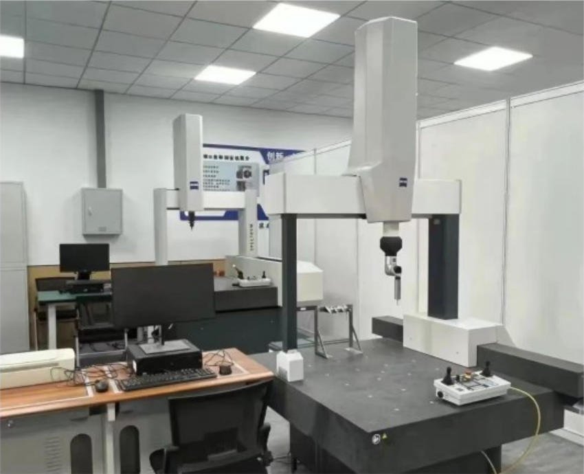
ISO 10360 is a family of acceptance and reverification tests for coordinate measuring systems. For example, ISO 10360-3 addresses CMMs using a rotary table as a fourth axis. The family evaluates machine performance under defined conditions; it does not mean every measurement made on a compliant machine is automatically fit for every tolerance.
Request current calibration or verification status appropriate to the equipment, but also evaluate the specific measurement process. Probe configuration, stylus length, fixturing, thermal condition, accessibility and software method can dominate a difficult feature.
Measurement Uncertainty Matters Near Limits
Every result has uncertainty. When an actual value lies close to a specification limit, a simple green/red color can overstate confidence. Buyer and supplier should agree on a decision rule: how uncertainty is considered when declaring conformity.
NIST’s publication on measurement uncertainty for coordinate measuring machines explains that CMM uncertainty involves machine and measurement considerations. Use that principle to ask for process capability, not a generic machine accuracy slogan.
Never invent a universal “guard band.” The appropriate rule depends on tolerance, risk, uncertainty evaluation and contract.
Environmental and Part Condition
Temperature gradients, part heat, cleanliness, burrs, oil, magnetic chips, fixture force and vibration affect measurement. The report should identify material condition and unusual controls where they are significant.
Allow parts and gauges to stabilize under the agreed environment. Clean without altering edges. Thin or compliant components can deform under clamps or probe force; fixture strategy must support the functional state without forcing the part into nominal geometry.
For hardened mold inserts, verify whether measurement occurred before or after heat treatment, grinding, EDM recast removal, coating and final polishing. Results from an intermediate state cannot release the finished feature.
Surface and Edge Conditions
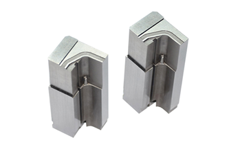
CMM contact on a rough EDM surface, radiused edge or polished transition can locate a different apparent point from the CAD ideal. Define whether the characteristic is measured on machined stock, final surface or theoretical intersection.
Burrs can create false highs and also indicate a real manufacturing problem. Do not simply filter them out in software. Inspect and disposition the physical edge.
Features inaccessible to the probe may need another method such as optical measurement, surface metrology, gauge, roundness instrument or sectioning. A complete inspection plan can combine methods; forcing every characteristic onto a CMM is not a quality strategy.
Report Types
First-article report
Confirms the first complete production route against all agreed characteristics and revision. It should include balloon mapping and material/process documents required by the order.
In-process report
Tracks critical features before the next irreversible operation. It may contain fewer dimensions but needs lot and stage traceability.
Final or shipment report
Supports release of finished parts. It should identify sampling, serials or cavities and disposition of any deviation.
Do not confuse a layout report from one piece with statistical control of a batch.
Sampling and Traceability
Specify whether the report covers every component, selected serials, each cavity, each machine setup or a lot sample. For interchangeable mold components, risk may justify more extensive reporting on critical fits.
Mark parts where practical and preserve the link from measurement file to physical item. If results are pooled without serial identity, a buyer cannot isolate a failed piece.
Sampling standards can guide lot decisions, but critical safety or functional characteristics may require different controls. State the plan in the purchase order.
How to Review a Characteristic Line
- Locate the balloon on the correct drawing revision.
- Confirm unit, nominal and tolerance interpretation.
- Check datum reference and feature definition.
- Review actual, deviation and conformity decision.
- Consider proximity to limit and uncertainty rule.
- Confirm the inspected part and process stage.
- Review trend against prior pieces or cavities.
Repeat this on risk characteristics rather than scanning only for red cells.
Nonconformance Is a Workflow
A failed result should trigger containment, verification, cause analysis and disposition. The supplier must not edit the program, delete points, remeasure until a pass appears or blend the feature without authorization.
Record original result, verification method, affected quantity and approved disposition. Rework requires reinspection and traceability. Use-as-is requires buyer authority where the contract demands it.
If report and independent measurement disagree, first reconcile revision, temperature, datum simulation, feature algorithm and decision rule before accusing either machine.
RFQ Checklist
- Controlled 2D drawing and 3D model with precedence defined.
- Ballooned characteristic list and critical-feature classification.
- Datum and fixture requirements.
- Measurement method for difficult or inaccessible features.
- Required report format and raw-data retention.
- Equipment verification and uncertainty expectations.
- Sampling by lot, cavity, setup or serial.
- Decision rule near tolerance limits.
- Nonconformance and rework authorization path.
- Final document package and language.
Red Flags
- No drawing revision or part identifier.
- All results show identical trailing zeros.
- Datum alignment is unnamed.
- Geometric tolerances are reduced to simple coordinate checks.
- Calibration certificate is offered as the only process evidence.
- Critical results sit exactly on limits with no uncertainty discussion.
- Failed points disappear from the revised report.
- One report is reused for multiple untraceable pieces.
Frequently Asked Questions
Does a CMM automatically inspect GD&T correctly?
No. Software needs the correct datum alignment, feature construction, modifiers and evaluation method. Review the program strategy and drawing interpretation.
How many probe points are enough?
There is no universal number. It depends on feature form, tolerance, size, accessibility and evaluation goal. The point pattern must represent the feature rather than merely satisfy a minimum count.
Is more decimal precision better?
Not by itself. Displayed digits must be supported by the measurement process and uncertainty. Extra decimals can create false confidence.
Should buyers request raw CMM files?
For critical work, agree on retention and access before ordering. At minimum, require traceable reports and preservation of the measurement program and results for the contracted period.
Final Decision Rule
Accept a CMM report only when you can trace every critical result from the controlled drawing to the measured part, datum alignment, feature method and conformity decision. The report is not a decorative certificate; it is a technical argument that the manufactured component meets functional requirements under an agreed measurement process.
For digital handoff, retain the signed PDF, native result where contractually required, ballooned drawing, program revision, calibration status, deviation approvals and part/lot mapping. Protect records from silent regeneration after a drawing or software change. A revised report should preserve the original and explain why it changed. Buyers can then distinguish a legitimate corrected header from altered measurement evidence and can reproduce the acceptance logic during mold maintenance or replacement-part ordering.