
Precision Lifter Mold Components — +/-0.001 mm Accuracy, 24-Hour Quotes
ISO 9001:2015-certified lifter components machined on Sodick slow-wire EDM and Fanuc CNC, with ZEISS CMM validation, full FAI reports and DFM support from 10+ engineers.
Featured Lifter & Mold Component Solutions
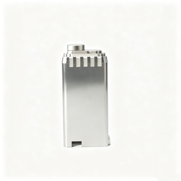
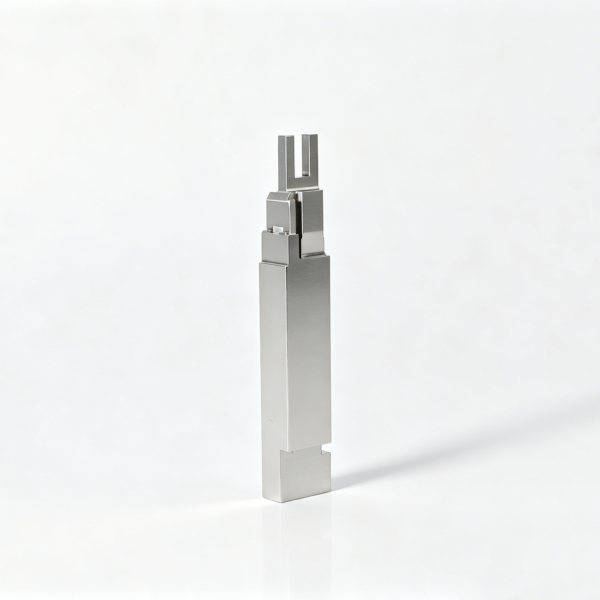
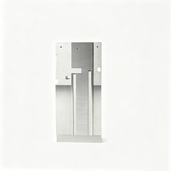
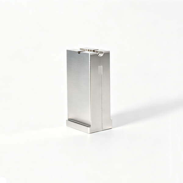
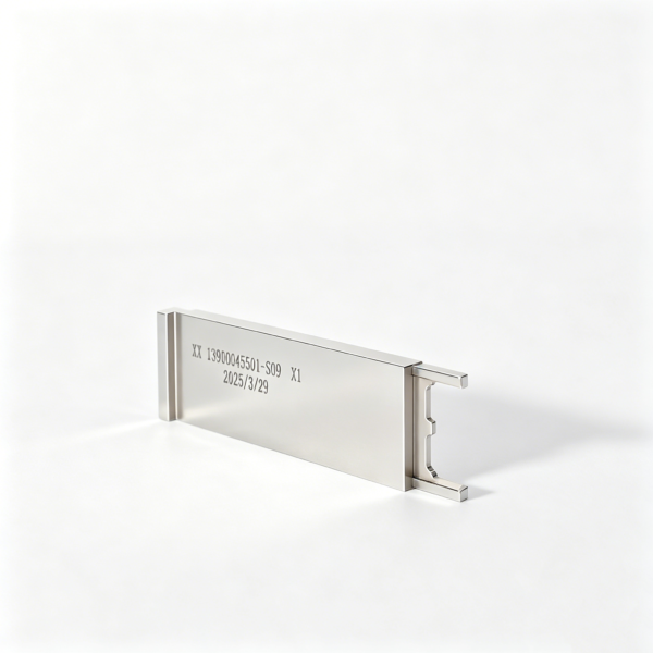
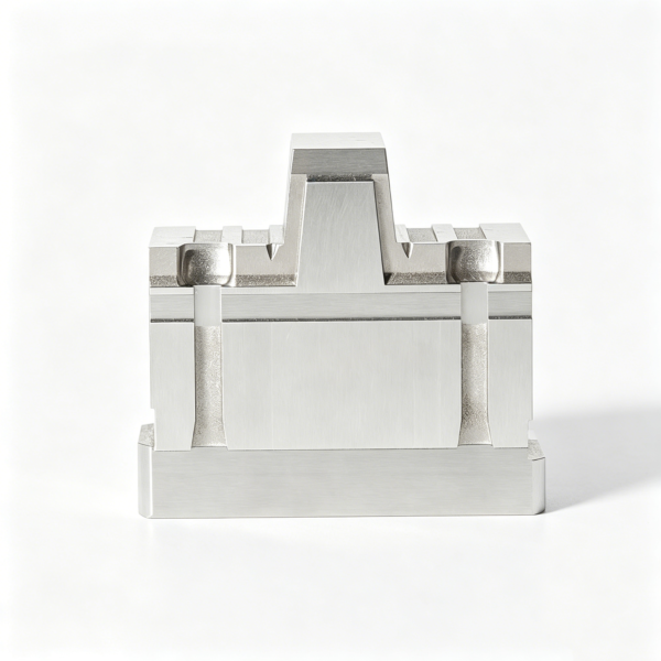
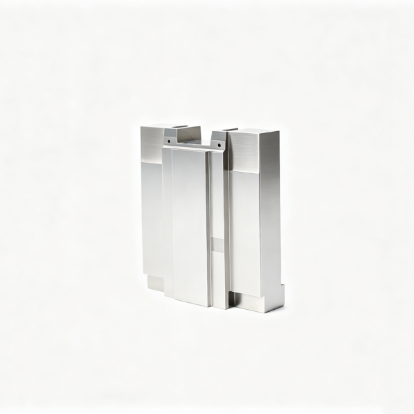
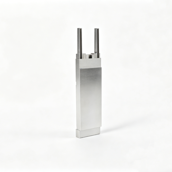
Precision Lifter & Mold Component Gallery
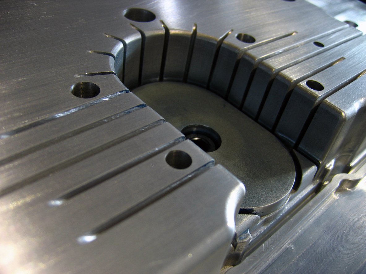
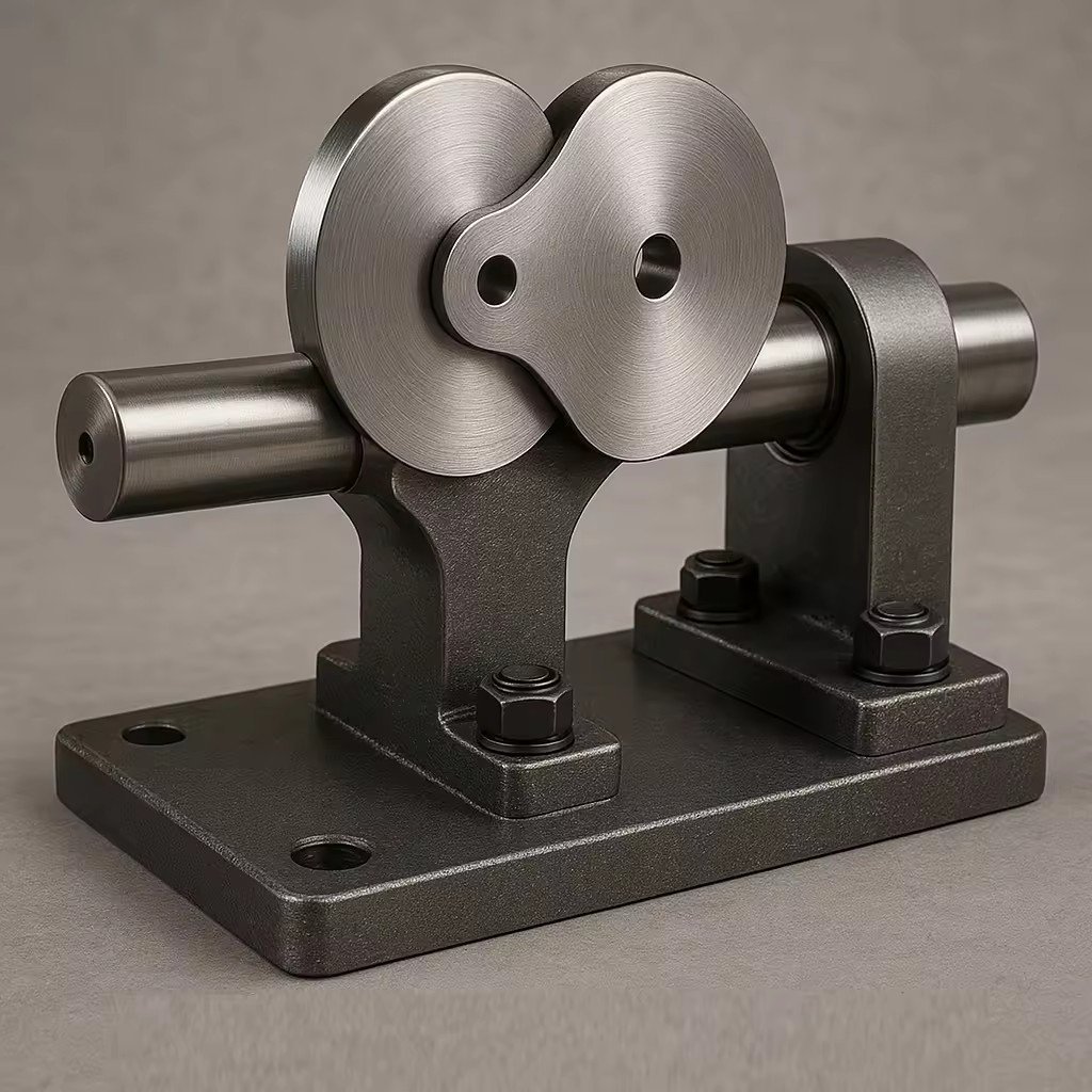
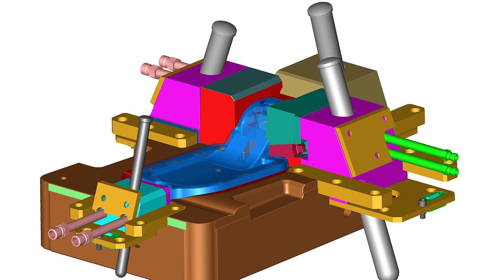
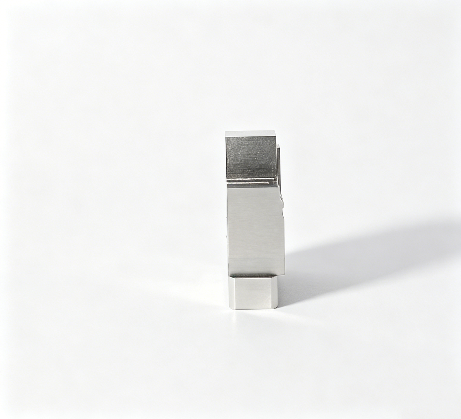
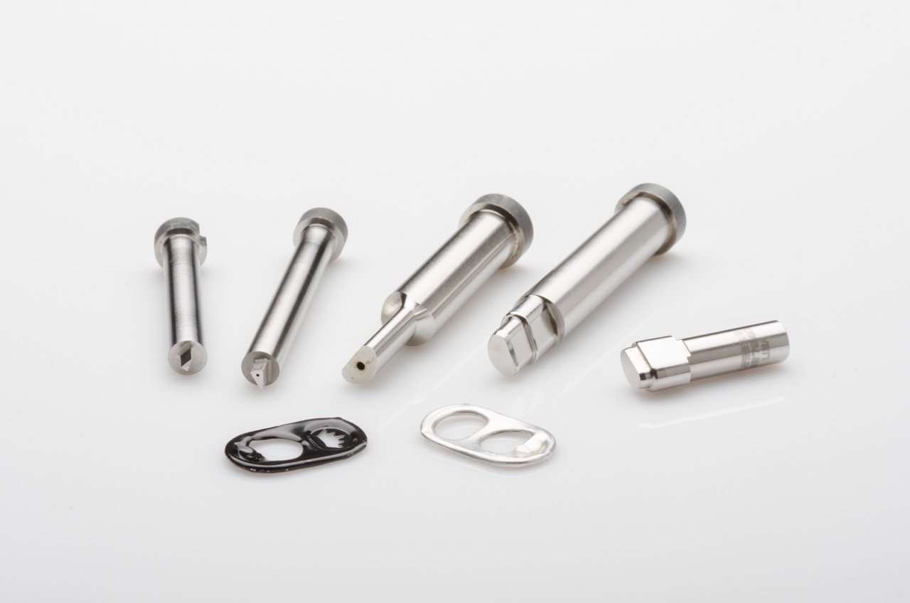
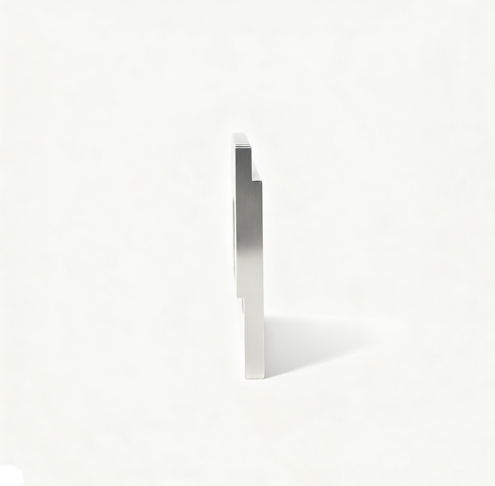
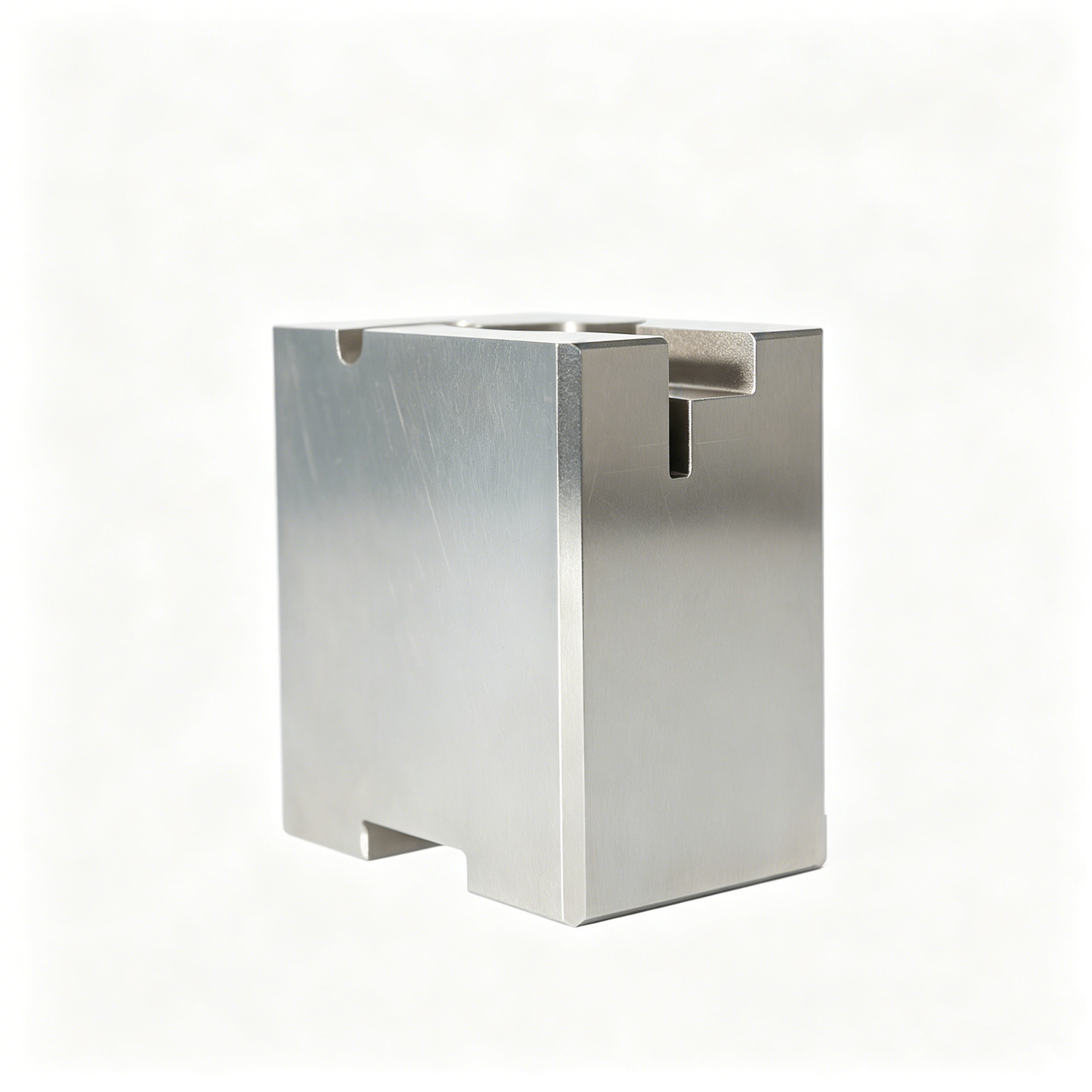
XUXIANG Lifter Component Precision Advantages
+/-0.001 mm Machining Precision
Sodick slow-wire EDM and Fanuc CNC hold micron-stable tolerances on every lifter core, slider and insert — eliminating tolerance failure at the source.
Mirror-Grade EDM Finish
Mitsubishi mirror EDM delivers Ra 0.1 µm surface quality on complex lifter geometries, ensuring flawless part release and extended mold life.
ZEISS MICURA CMM Validation
Every lifter component is verified to 0.7 µm resolution with full FAI reports and material certificates — proof, not promises.
24-Hour Quote Turnaround
Upload your CAD file and receive a detailed, DFM-reviewed quotation within one business day — no delays, no guesswork.
Dual-Factory Production Capacity
Dongguan R&D micro-machining center plus Quanzhou volume facility deliver samples in 3–7 days, mass production in 15–25 days.
ISO 9001:2015 Quality System
Five-step QC flow — spectral analysis, in-process monitoring, CMM verification, surface checks and final FAI — governed by 16 years of precision expertise.
Lifter & Mold Component Categories
Micron-stable lifters, slides and core systems machined to +/-0.001 mm — engineered to eliminate undercut defects, reduce cycle time and extend tool life across electronics, automotive and connector molds.
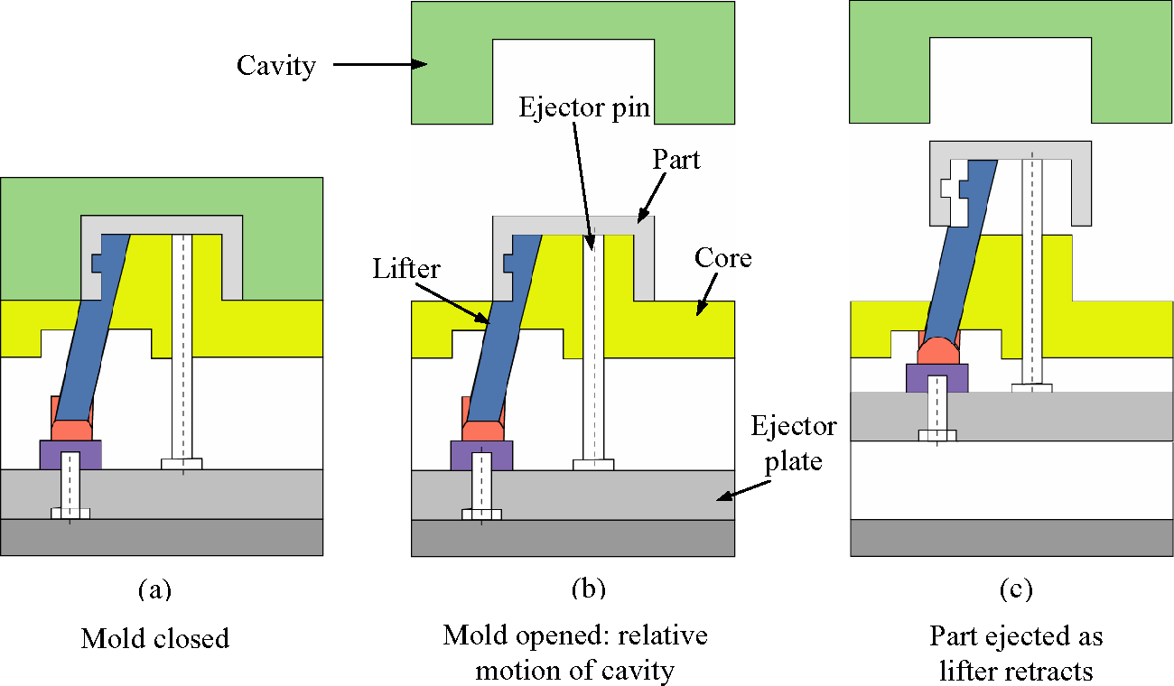
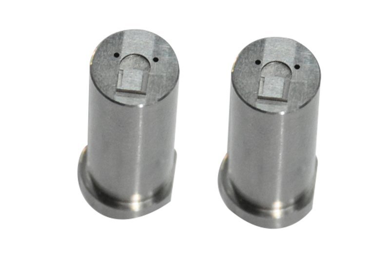
Ejector Lifters
Ejector lifters machined to +/-0.002 mm positioning tolerance on Sodick slow-wire EDM and Fanuc CNC, designed to release complex undercuts during part ejection. Ideal for multi-cavity electronics housings and thin-wall connector shells where ejection force and alignment repeatability are critical. DFM review identifies interference risks before fabrication; ZEISS CMM validation ensures cam-angle accuracy and surface finish down to Ra 0.2 μm.
Get a Quote
Angle Lifters
Angle lifters with precision cam surfaces and wear-resistant coatings, held to +/-0.001 mm on critical angles and slide faces. Used in automotive interior trim molds, ADAS sensor housings and industrial enclosures requiring reliable side-core actuation. Sodick mirror EDM delivers Ra 0.1 μm finish on cam tracks; Nikon toolmaker’s microscope verifies edge break and corner radius down to R 0.015 mm to prevent galling over high-volume production runs.
Get a Quote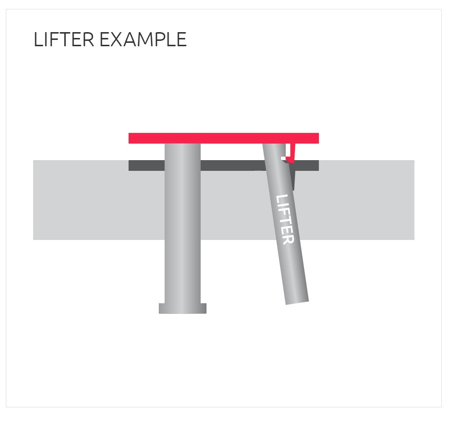
Slide Lifters
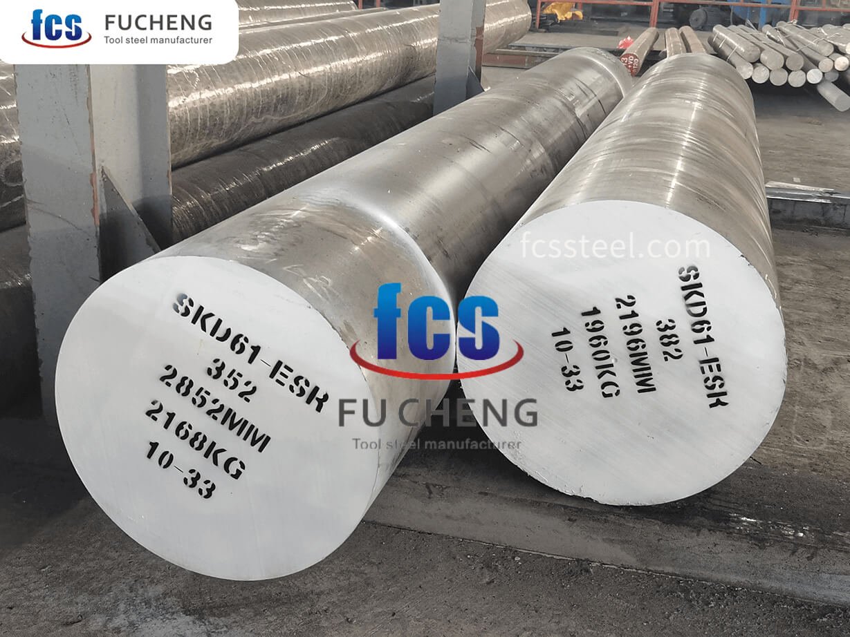
Slide lifters engineered for high-cycle connector and automotive molds, combining slow-wire EDM precision with heat-treated tool steel (SKD61, SKH51) for dimensional stability under thermal cycling. Tolerances of +/-0.002 mm on slide rails and locking features ensure zero-flash parting and consistent gate vestige. Full FAI documentation includes material certificates, hardness reports and CMM data for every sliding surface and datum feature.
Get a Quote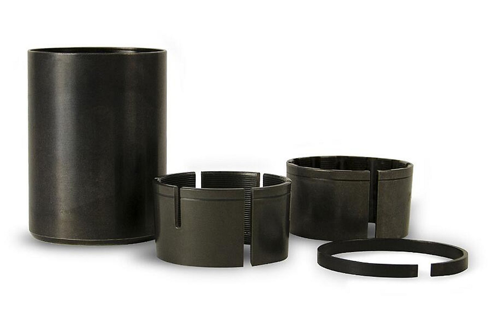
Core Lifters
Core lifters designed to actuate internal features in complex injection molds — threaded inserts, internal ribs and micro-pin arrays in 5G RF connectors, medical-device housings and NEV battery-management-system covers. Machined on Beijing Jingdiao high-precision CNC and finished by Mitsubishi mirror EDM to Ra 0.1 μm. DFM engineering from 10+ experts optimizes cam geometry, draft angles and ejection sequence to eliminate core pull failures and reduce mold maintenance.
Get a Quote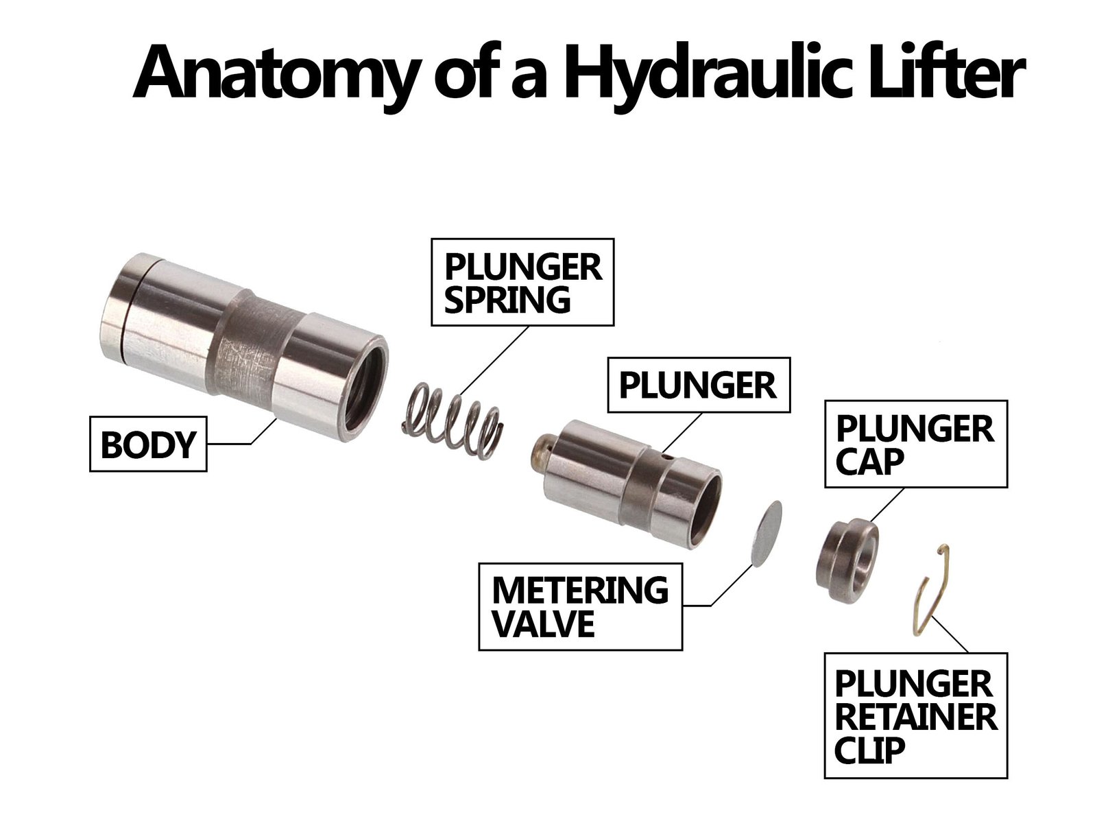
Hydraulic Lifters
Hydraulic lifters for large-format automotive and industrial molds requiring controlled, high-force undercut release — bumper clips, HVAC ducts and robotic end-effector housings. Precision-bored cylinders and piston rods held to +/-0.003 mm on Fanuc CNC; seal grooves and porting verified by ZEISS MICURA CMM to 0.7 μm resolution. Integrated pressure-relief features and corrosion-resistant coatings extend service intervals and minimize downtime in high-tonnage presses.
Get a Quote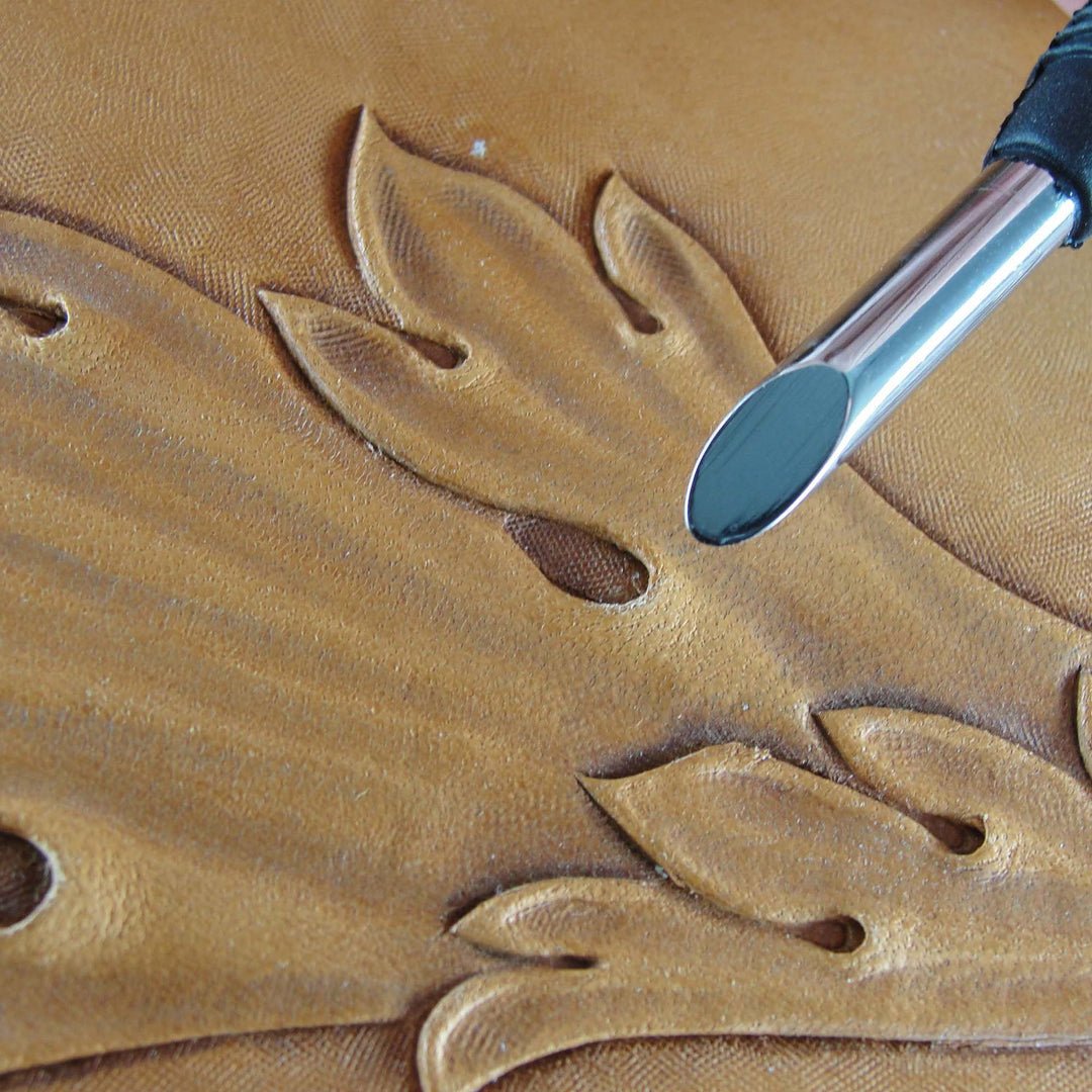
Undercut Lifters
Undercut lifters purpose-built for micro-connector tooling, board-to-board sockets and FPC assemblies where pin-to-pin pitch is below 0.4 mm. Sodick and Seibu slow-wire EDM achieve +/-0.001 mm on lifter travel and locking surfaces; mirror-grade finish prevents resin bleed and ensures clean part release. Every lifter ships with Nikon microscope imagery of critical edges, plus dimensional reports traceable to ISO 9001:2015 calibration standards.
Get a Quote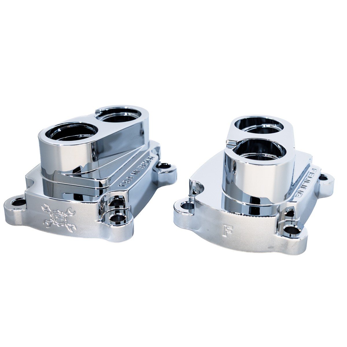
Lifter Blocks
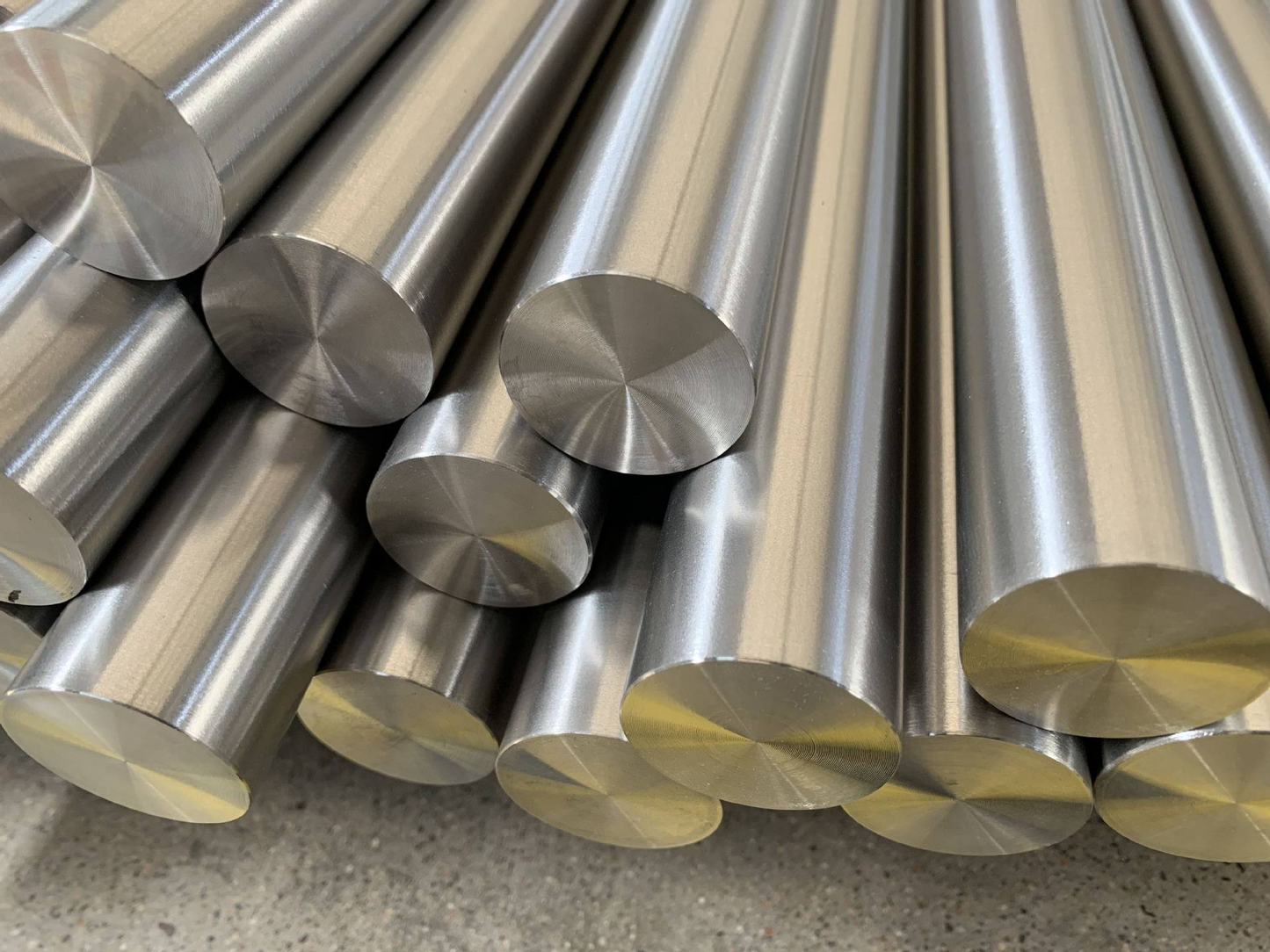
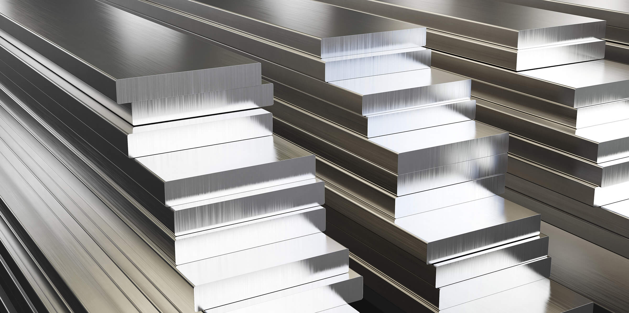
Lifter blocks machined from pre-hardened tool steel (P20, 718H) or hardened alloy (SKD61, NAK80) with precision-ground mounting faces and dowel-pin locations held to +/-0.002 mm. Used as structural bases in modular mold systems for electronics, automotive sensors and industrial automation fixtures. Dawn precision grinding centers deliver flatness within 0.005 mm over 200 mm span; all blocks are stress-relieved and dimensionally verified before shipment to prevent warpage during mold assembly.
Get a Quote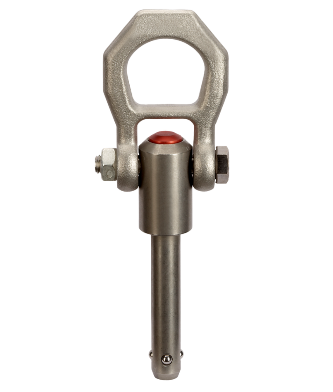
Lifter Pins
Lifter pins in diameters from 1.0 mm to 25 mm, ground to h6 tolerance and finished to Ra 0.2 μm or better on centerless grinding equipment. Materials include high-speed steel (SKH51), carbide and nitrided alloy for wear resistance in high-volume production. Critical for ejector-plate assemblies, slide-return mechanisms and limit switches in precision connector molds. Every pin lot includes diameter, straightness and surface-finish certification traceable to ZEISS and Nikon metrology.
Get a Quote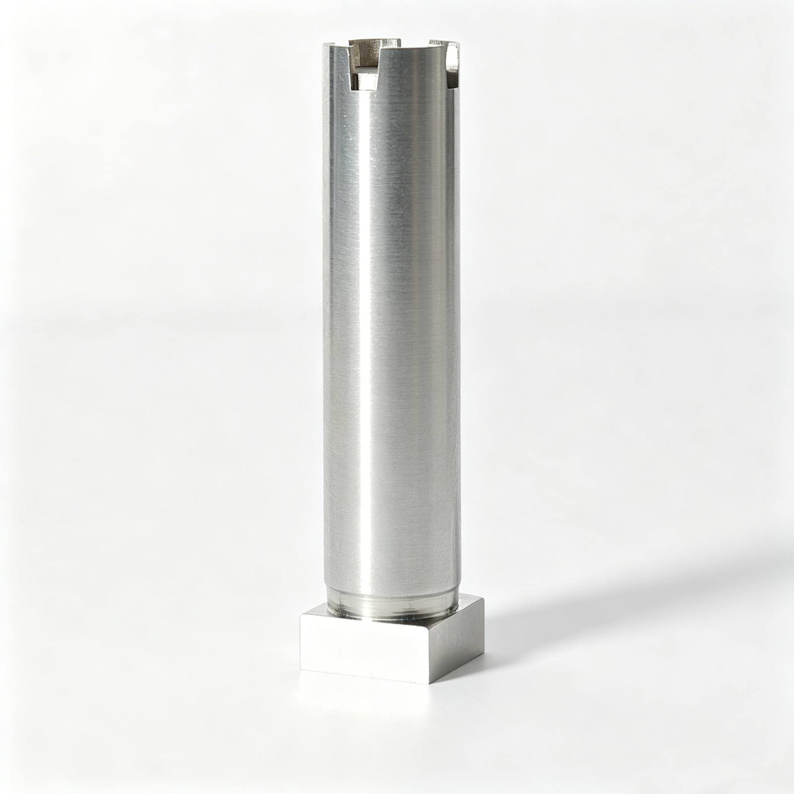
Custom Lifter Systems
Custom lifter systems co-engineered with your tooling team — combining cam-driven, hydraulic and mechanical actuation tailored to part geometry, production volume and press constraints. XUXIANG’s 16 years of mold-component experience and dual-factory capacity (Dongguan + Quanzhou) support rapid prototyping in 3–7 days and scalable production in 15–25 days. DFM analysis, 3D tolerance simulation and full FAI reports with material certificates ensure first-article success and long-term mold performance.
Get a QuoteMaterials & Specifications for Lifter Components

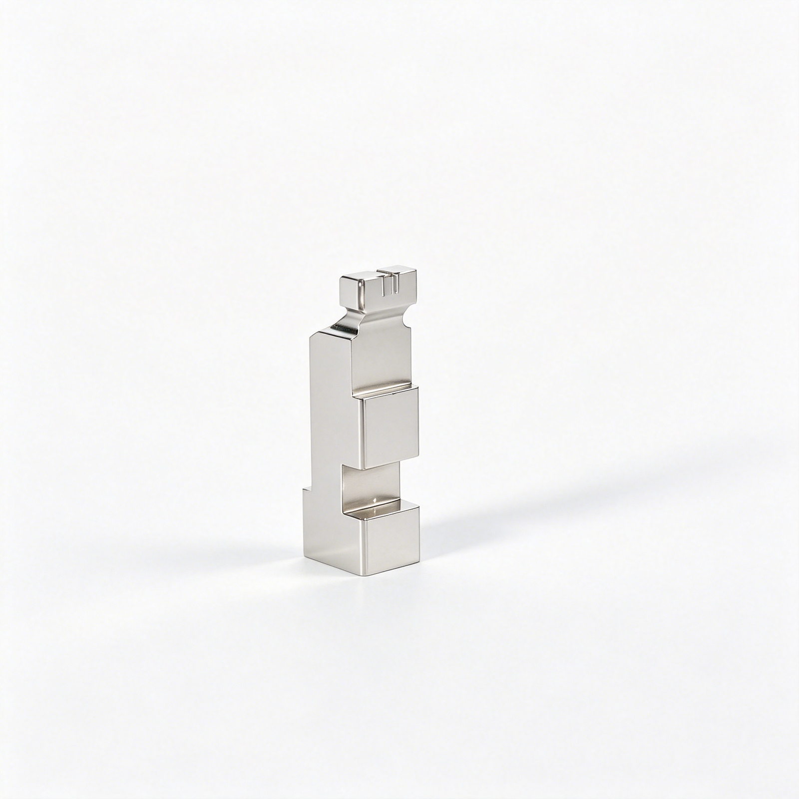
Precision Machining & EDM Processes for Lifters
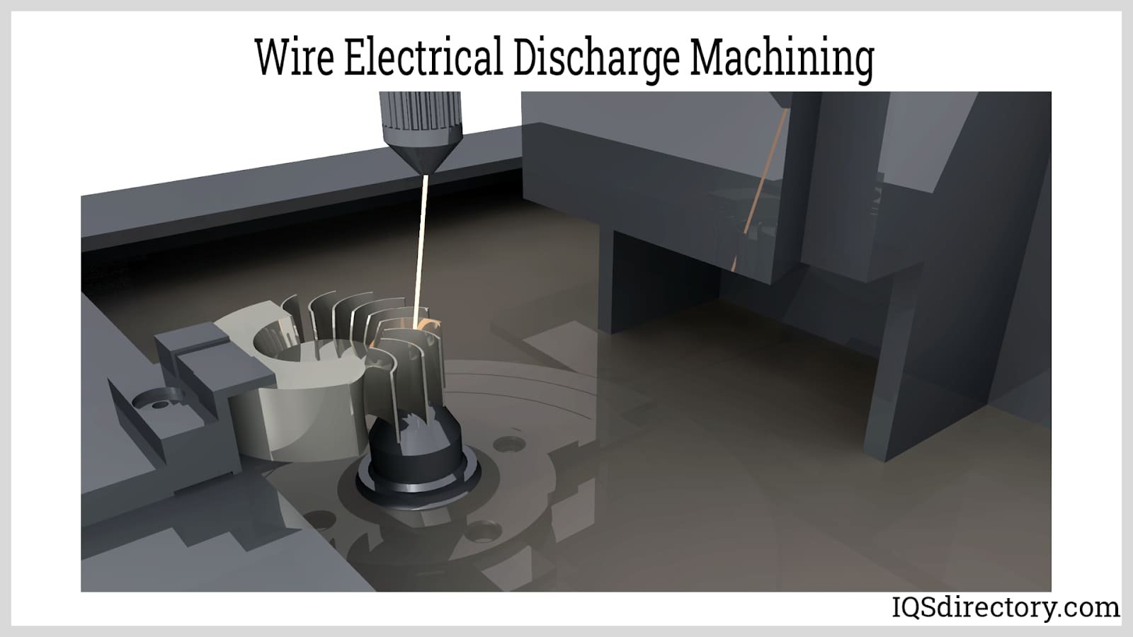
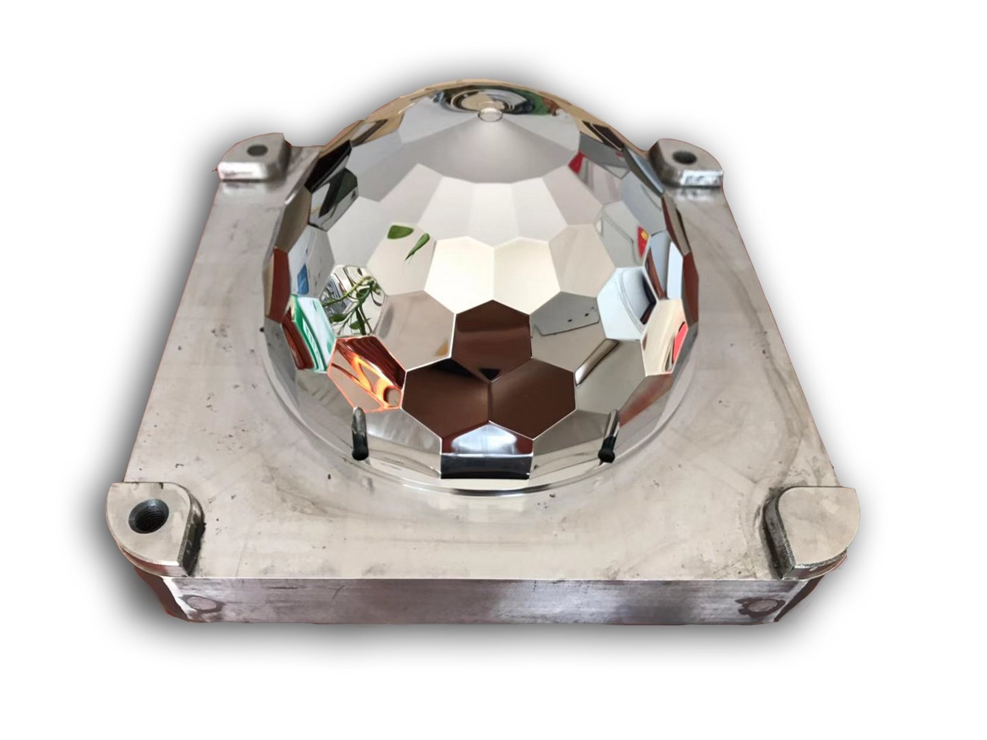
Mirror EDM
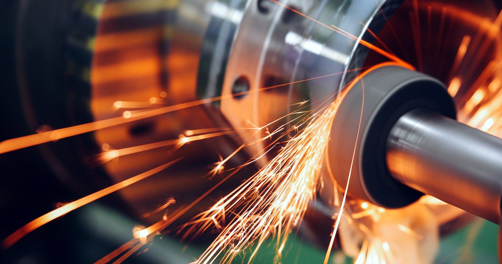
Mitsubishi mirror-grade EDM finishing achieves surface roughness down to Ra 0.1um on lifter contact faces and slide surfaces, eliminating secondary polishing while ensuring optimal mold release and extended tool life in high-cycle applications.
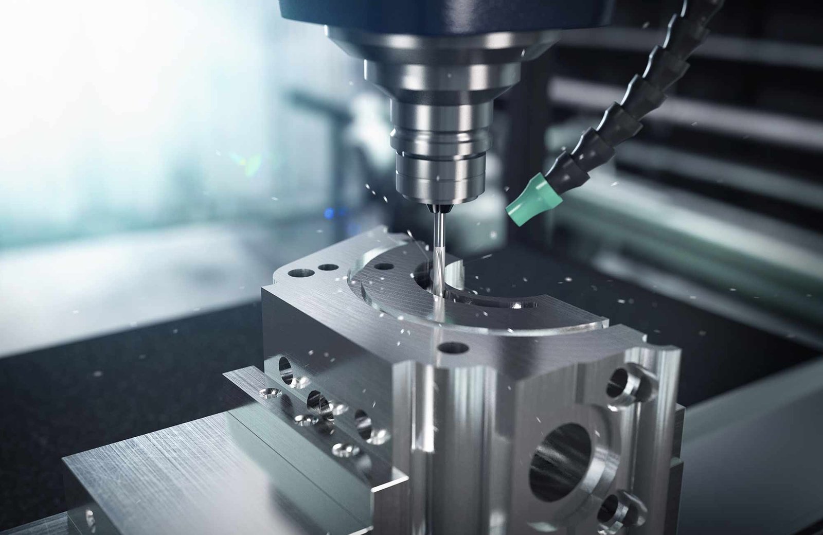
Electrode Fabrication
Beijing Jingdiao high-precision CNC systems fabricate custom graphite and copper electrodes for sinker EDM, enabling deep ribs, undercuts, and micro-features on lifter cores that cannot be reached by conventional machining or wire EDM.

ZEISS CMM Validation
Every lifter component undergoes ZEISS MICURA CMM inspection with 0.7um resolution, generating full FAI reports that verify critical dimensions, geometric tolerances, and surface integrity before shipment — eliminating field rework and assembly delays.
Finishing & Assembly Options for Lifter Tooling
Heat Treatment & Hardening
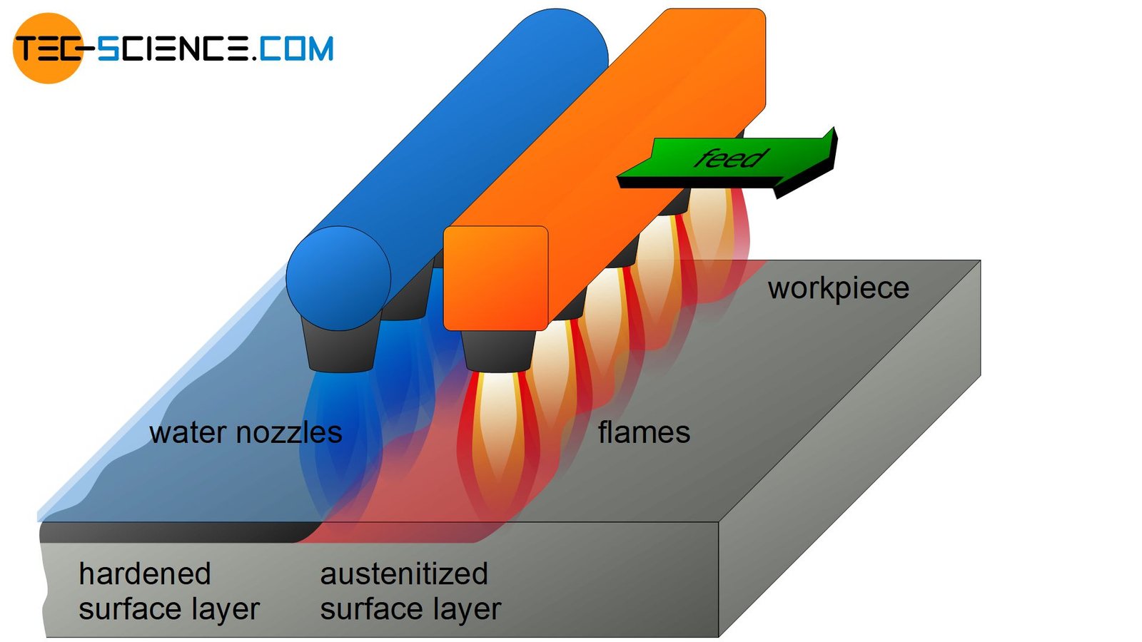
Vacuum hardening (HRC 48–62) and nitriding for wear-resistant lifter surfaces. Ensures dimensional stability under high-cycle molding and extends tool life in abrasive or high-temperature applications. Full hardness testing and certificates included.
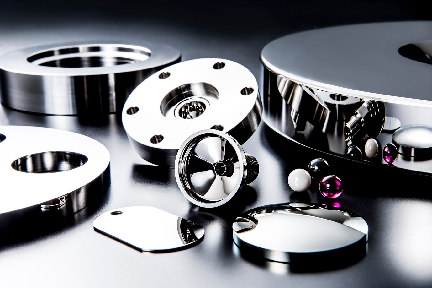
Mirror Polishing & Finishing
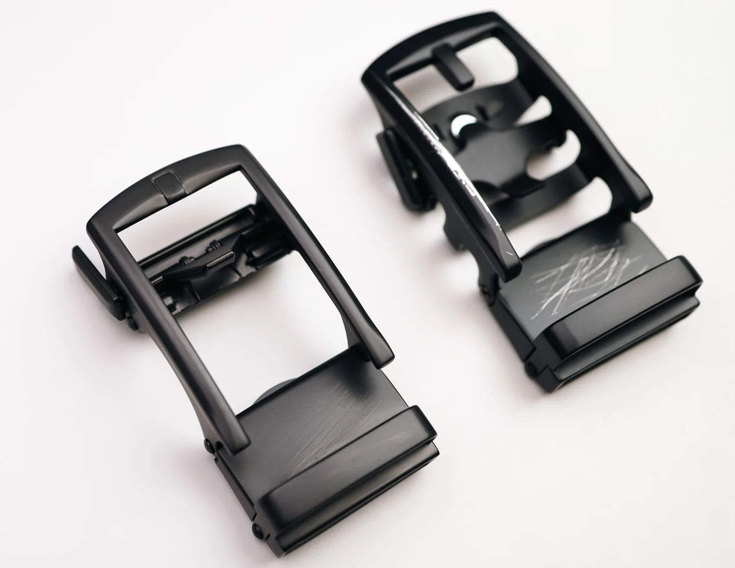
Ra 0.1–0.2 µm mirror-grade polishing on lifter contact faces and sliding surfaces, executed on Mitsubishi mirror EDM and manual polishing benches. Eliminates parting-line flash, reduces ejection force and improves cosmetic part quality.
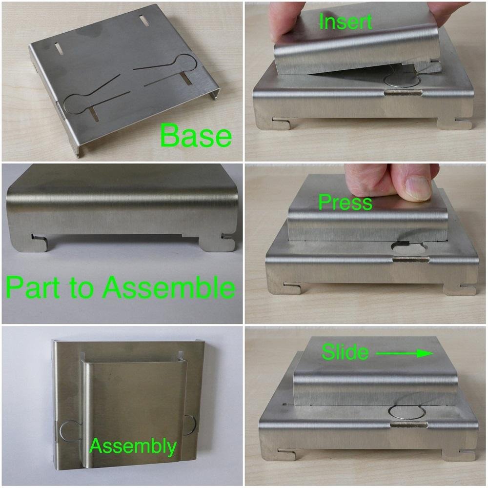
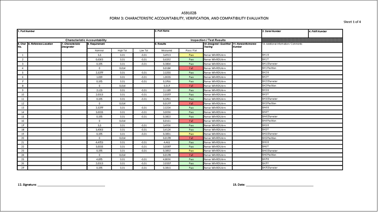
FAI & Material Certificates
First-article inspection reports generated on ZEISS MICURA CMM (0.7 µm resolution), complete with material spectral analysis, hardness data, dimensional tables and traceability certificates. Full compliance documentation for ISO and automotive-tier audits.
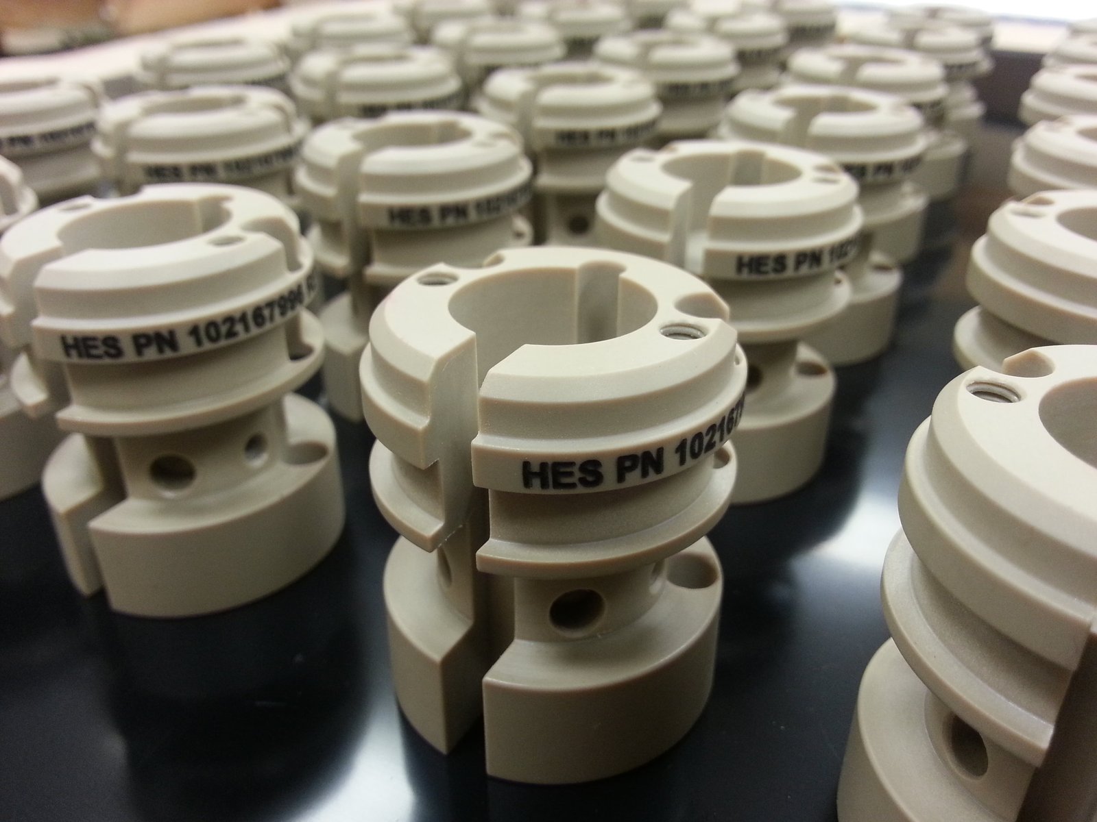
About XUXIANG — Precision Lifter Manufacturing Since 2010
Founded in 2010 in Dongguan’s Chang’an manufacturing hub, XUXIANG has evolved from a specialist mold-core machining shop into a dual-factory precision manufacturing group serving electronics, 5G/telecom, automotive & NEV, industrial-automation and medical-device customers worldwide. Our mission: bridge the gap between complex CAD designs and high-performance physical parts with micron-stable precision and dependable delivery.
Today XUXIANG operates 3,400 m² across two ISO 9001:2015–certified facilities — a 2,000 m² Dongguan R&D and micro-machining center, plus a 1,400 m² Quanzhou volume-production plant launched in 2025. This expansion lifted annual capacity by a targeted 200 percent, combining precision-grade tooling with mass-production scale. Our shop floor integrates over CNY 8 million in Japanese, Swiss and German assets: Sodick and Seibu slow-wire EDM, Mitsubishi mirror EDM, Fanuc CNC and a ZEISS MICURA CMM measuring to 0.7um.
What sets XUXIANG apart is engineering-led quality control: every lifter, slider and mold insert passes a five-step validation flow — material spectral analysis, in-process tolerance monitoring, ZEISS/Nikon CMM verification, surface-integrity checks and final FAI documentation with material certificates. With 10+ DFM experts on staff and quotes returned in 24 hours, we deliver the precision you specify and the partnership you deserve.

XUXIANG Precision Manufacturing — Lifter Components Since 2010
+/-0.001mm Machining Accuracy for Every Lifter
XUXIANG holds maximum machining accuracy of +/-0.001mm across CNC, EDM and grinding operations — critical for lifter slides, angled cores and multi-cavity inserts where even 2-micron drift causes flash, ejection failure or dimensional rejection at incoming inspection.
- Sodick & Seibu slow-wire EDM: +/-0.002mm class positioning, R ≤ 0.015mm corner radii
- Fanuc CNC and Beijing Jingdiao electrode centers: +/-0.001mm repeatability
- Dawn precision grinding: flatness and parallelism held to 0.002mm across mating surfaces
- In-process tolerance monitoring at every operation — no cumulative stack-up
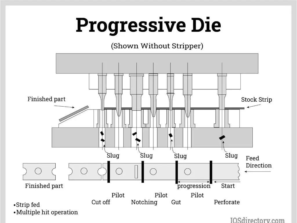
Ra 0.1µm Mirror EDM Finish
Mitsubishi mirror-grade EDM and Sodick sinker systems deliver Ra 0.1µm surface finishes on lifter contact faces, slide rails and cavity details — eliminating hand-polishing, reducing friction wear and ensuring consistent part release over hundreds of thousands of cycles.
- Mirror-class EDM on complex 3D profiles, undercuts and angled lifter geometries
- No secondary polishing required — as-machined Ra 0.1µm finish straight from the electrode
- Reduced coefficient of friction extends lifter service life and minimizes maintenance intervals
- Consistent surface integrity across production batches — validated by Nikon MM-400 microscopy
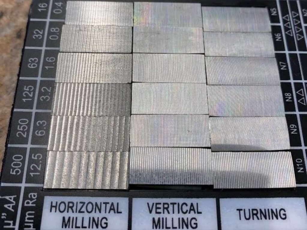
ZEISS MICURA CMM Validation to 0.7µm
Every lifter component undergoes full-form CMM verification on ZEISS MICURA coordinate measuring equipment, with 0.7µm resolution and temperature-controlled metrology lab — delivering FAI reports, GD&T compliance and material certificates that pass OEM incoming inspection without rework.
- ZEISS MICURA CMM: 0.7µm measurement accuracy in climate-controlled environment
- Nikon V-12B and MM-400 toolmaker's microscopes for micro-feature and edge-quality inspection
- Full FAI documentation with dimensional reports, material spectral analysis and surface-integrity data
- Five-step QC flow: material verification → in-process monitoring → CMM validation → surface checks → final pack-out
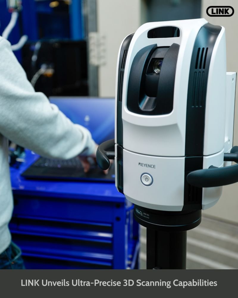
DFM Engineering Support from 10+ Experts
Before any lifter component enters production, XUXIANG’s team of 10+ mold-design and machining engineers reviews your CAD files for manufacturability, tolerance optimization, ejection clearance, draft angles and tool-life risk — reducing prototype iterations and preventing costly mid-run corrections.
- Pre-production DFM review: tolerance stack-up, draft analysis, undercut feasibility and material selection
- Collaborative engineering: red-line feedback, alternative geometries and cost-reduction suggestions
- 16 years of precision-mold experience across electronics, automotive, 5G/telecom and medical devices
- Quote returned within 24 hours — with DFM notes, lead-time estimate and recommended finishing options
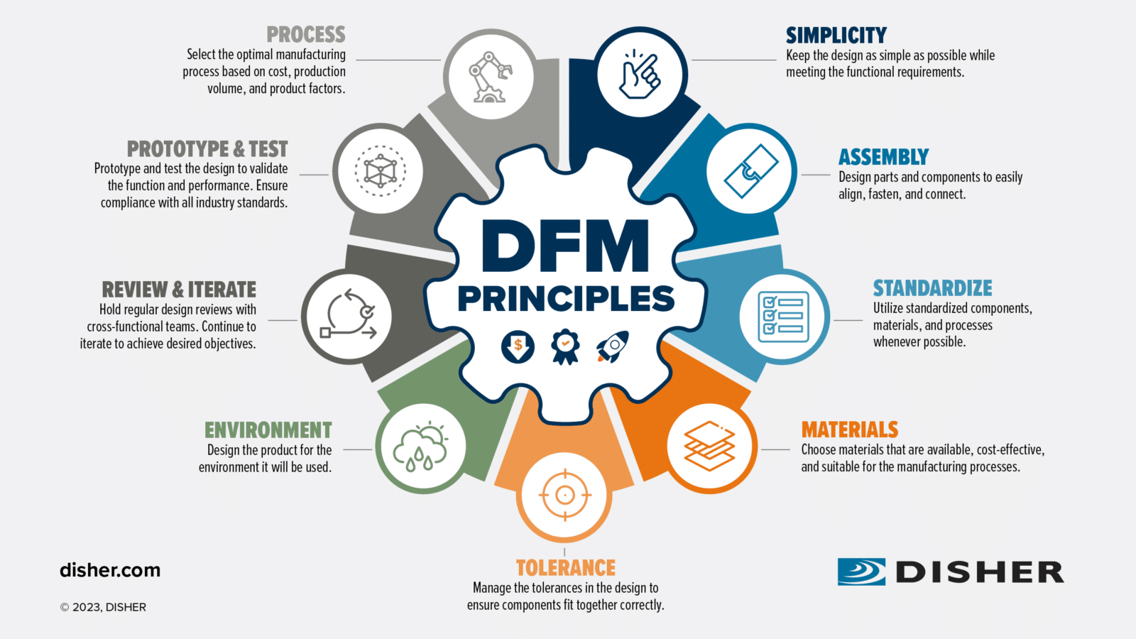
Why Choose XUXIANG for Lifter & Mold Components
Head-to-head comparison of precision, speed, quality systems and engineering support — backed by concrete metrics and verifiable tolerances.
← 左右滑动查看 →
XUXIANG Lifter & Mold Component Production Flow
Every precision lifter and mold component moves through a six-phase quality gate — from DFM engineering to ZEISS-validated FAI — ensuring micron-stable delivery on every order.
DFM Review & Engineering
10+ experts analyze your CAD files for manufacturability, tolerance feasibility and tooling optimization before production begins — preventing costly rework downstream.
Material Sourcing & Spectral Analysis
Certified alloys and tool steels undergo spectral analysis to verify composition and traceability, ensuring material integrity for every lifter and core insert.
Precision Machining & EDM
Sodick slow-wire EDM, Mitsubishi mirror EDM and Fanuc CNC deliver +/-0.001 mm accuracy and Ra 0.1um finishes on complex lifter geometries and mold cores.
In-Process Tolerance Monitoring
Real-time dimensional checks at critical machining stages catch drift before it compounds, maintaining tight control across multi-operation lifter production runs.
ZEISS & Nikon CMM Validation
ZEISS MICURA CMM (0.7um resolution) and Nikon toolmaker’s microscopes verify final dimensions, surface finish and geometric tolerances against your print and ISO standards.
Surface Integrity & FAI Documentation
Final surface-integrity inspection and First Article Inspection reports with material certificates accompany every shipment, providing full traceability and compliance evidence.
How to Source Lifter Components from XUXIANG
From CAD upload to on-time delivery, our five-step process removes the friction from precision mold component procurement.
Submit Your CAD & Requirements
Upload 2D/3D drawings, technical specifications and tolerance requirements via our secure portal or email — we accept all standard file formats.
Receive DFM Feedback & Quote
Within 24 hours, our 10+ engineering experts deliver manufacturability analysis, tolerance recommendations and a transparent, itemized quotation for your lifter components.
Approve Sample Production
Confirm the quote and specifications; XUXIANG machines first-article samples in 3–7 days, validated by ZEISS MICURA CMM and shipped with full inspection reports.
Launch Mass Production with FAI
After sample approval, volume orders enter our ISO 9001:2015 workflow — Sodick EDM, Fanuc CNC and five-stage QC — completed in 15–25 days with FAI documentation.
Receive On-Time Delivery & Support
Parts ship with material certificates, dimensional reports and traceability documentation; our dual-factory capacity ensures delivery roughly 30% faster than industry average.
ISO 9001:2015, Material Certifications & Quality Badges for Every Lifter Component



Customer Testimonials — Lifter & Mold Component Success Stories
XUXIANG’s lifter components cut our mold-cavity rework by 38% and held +/-0.002 mm across 12,000 cycles. Their ZEISS inspection reports gave us full traceability, and delivery was 9 days ahead of schedule.
We needed mirror-finish lifter cores for automotive sensor housings with Ra 0.15um. XUXIANG achieved Ra 0.12um on every part, validated by their Nikon microscope. Zero rejections across three production runs.
Switching to XUXIANG for our micro-connector lifter tooling reduced our first-article approval time from 6 weeks to 11 days. Their DFM feedback caught two critical tolerance issues before machining even started.
FAQ — Lifter Components, Sampling & Procurement
What is the minimum order quantity for custom lifter components?
How long does it take to receive sample lifter parts?
Do you charge for sampling, and is the cost refundable?
What tolerances can you guarantee on lifter mold components?
What payment terms do you offer for lifter component orders?
How do you protect my IP and design data for custom lifter tooling?
Do you provide material certificates and inspection reports with every lifter shipment?
Can you machine lifter components from customer-specified materials?
What happens if a lifter part fails tolerance after delivery?
The Complete Buyer’s Guide to Lifter Mold Components for Precision Tooling
Navigate the critical decisions in sourcing lifter components for injection molds. This guide delivers a proven framework for evaluating suppliers, understanding tolerances and materials, avoiding costly specification errors, and ensuring micron-level repeatability in high-volume production.
1. What Is a Lifter in Injection Mold Tooling?
A lifter is a cam-actuated angled slide mechanism that releases internal undercuts or side-action features during mold opening, eliminating the need for secondary operations or part redesign. Unlike a straight core pin — which can only move perpendicular to the parting line — or a conventional slide that travels horizontally, a lifter combines angular motion with a wedge or heel block to pull features at compound angles, typically 10° to 30° from vertical, making it indispensable for automotive door clips, micro-connector housings with lateral retention hooks, and medical enclosures with snap-fit bosses.
Precision directly governs cycle reliability and part quality. A +/-0.001 mm positional error on the lifter’s angled face or cam surface can cause flash, drag marks or incomplete undercut release, leading to scrap rates above 5% in high-cavity tooling. XUXIANG machines lifter bodies and heel blocks to +/-0.002 mm on Sodick slow-wire EDM and validates cam angles with ZEISS MICURA CMM resolution of 0.7 µm, ensuring repeatable motion over millions of cycles without wear-induced drift.
2. Evolution of Lifter Design and Manufacturing Standards
In the 1980s lifter components were hand-fitted and lapped to final dimensions, routinely holding tolerances of ±0.01 mm — acceptable for consumer electronics but inadequate for automotive underhood applications. The shift to CNC wire-EDM in the mid-1990s enabled repeatable positioning within ±0.005 mm and drove the standardization of cam angles at 10°, 15° and 20°, simplifying interchangeability across mold platforms.
By the early 2000s, automotive OEMs mandated ±0.003 mm positional tolerances for powertrain sensor housings, prompting mold-component suppliers to adopt five-axis machining and slow-wire EDM capable of ±0.002 mm class work. Concurrently, PVD and nitriding coatings extended cycle life from ~500,000 to over 2 million shots in high-wear applications.
The 2010s saw the rise of modular lifter cartridges — pre-assembled base, cam and slide blocks — that cut mold assembly time by 40 % and allowed field replacement without full teardown. Today, medical-device and 5G micro-connector tooling routinely specify ±0.001 mm on lifter core fits, achievable only through ZEISS-class CMM validation and mirror-grade EDM finishes below Ra 0.2 µm.
3. Types of Lifter Mechanisms and Configurations
Lifter mechanisms fall into four primary configurations, each engineered to release specific undercut geometries at predictable cycle intervals. Selection depends on undercut depth, draft angle, production volume, and whether the part requires simultaneous or sequential ejection.
Angled Lifter
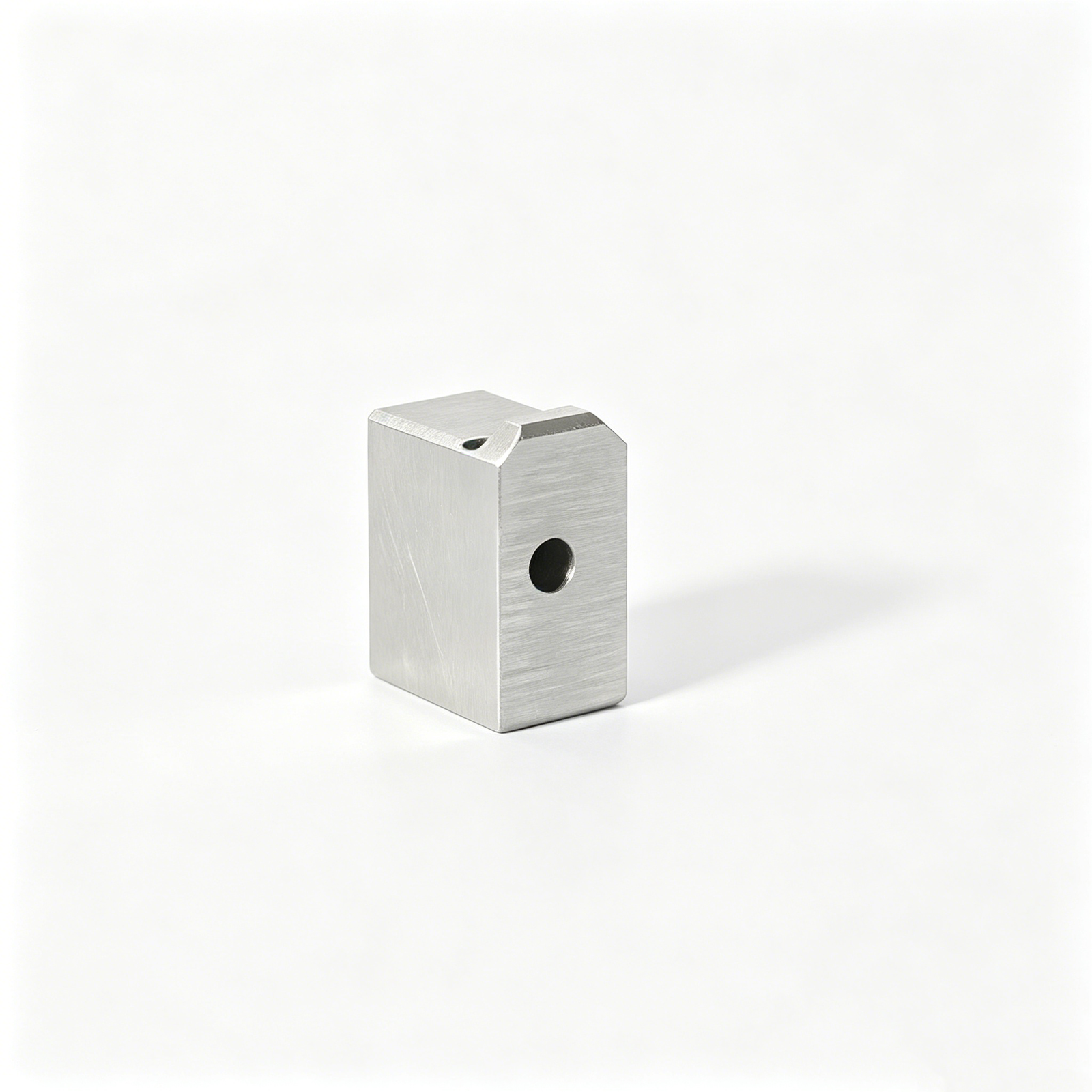
The angled lifter rides on an inclined wedge face — typically 15–25° — and retracts as the mold opens, clearing undercuts 2–8 mm deep. Cycle-time impact is minimal (adds ~0.2–0.5 s) because motion is mechanically coupled to platen travel.
Best for high-volume connector housings, automotive clips and consumer electronics enclosures where side-wall features repeat across cavities. XUXIANG machines angled-lifter wear surfaces to Ra ≤0.2 µm and holds slide angles within +/-0.01°.
Vertical Lifter
Vertical lifters move perpendicular to the parting line via a cam or rack system, releasing deep internal undercuts (5–15 mm) that angled geometry cannot reach. Cycle time increases 0.5–1.0 s due to sequential actuation.
Ideal for thick-walled medical housings, industrial connectors with internal locking tabs, and automotive sensor bodies. Specify when draft constraints or part thickness exceed 6 mm and undercut depth exceeds twice the wall thickness.
Compound-Angle Lifter

Compound-angle designs combine two or more motion vectors to clear complex 3D undercuts — common in multi-plane latch features and nested ribs. Undercut range spans 3–10 mm; cycle penalty is 0.8–1.5 s.
Reserve for mid-to-low volume (< 500k annual shots) where part revenue justifies tooling complexity. XUXIANG validates compound-lifter kinematics in DFM reviews to prevent interference and binding.
Hydraulic and Pneumatic Lifter
Hydraulic or pneumatic cylinders actuate lifters independently of platen motion, enabling precise timing and force control for fragile features or extreme undercut depths (> 12 mm). Cycle time adds 1.0–2.0 s; maintenance intervals shorten to ~200k cycles.
Specify for low-to-medium volume (< 200k shots/year) medical, aerospace or specialty automotive parts where undercut geometry or material sensitivity (PEEK, LCP) demands controlled ejection forces below 50 N.
4. Materials and Heat Treatment for Lifter Components
Material selection and heat treatment define lifter durability, wear resistance and corrosion performance across multi-million-cycle production runs. XUXIANG validates every batch through spectral analysis and hardness testing before machining.
| Material | Hardness (HRC) | Typical Cycle Life | Cost Index |
|---|---|---|---|
| H13 tool steel | 48–52 (wear surfaces) | >2M cycles | 1.0× |
| S136 stainless | 48–52 (post-harden) | >1.5M cycles (corrosive) | 1.4× |
| NAK80 pre-hardened | 28–32 (body/base) | >1M cycles | 1.2× |
| Beryllium copper | 28–35 (micro-lifters) | >800K cycles | 2.1× |
5. Critical Dimensional Tolerances and Surface Finishes for Lifters
Lifter performance and tool life depend on four critical dimensional parameters: slide-fit clearance, angle accuracy, flatness/parallelism, and surface finish. Under-specifying any of these invites flash, cycle-time drift, and premature wear.
Slide-Fit Clearance: 0.005–0.015 mm
The gap between lifter and guideway must balance free motion and leak prevention. Clearances below 0.005 mm risk seizing under thermal expansion; above 0.015 mm, resin flash appears at parting lines.
XUXIANG’s slow-wire EDM holds +/-0.002 mm positioning, ensuring consistent fits across production runs. Buyers should specify both nominal clearance and tolerance band — not just a single target — to avoid ambiguity in inspection.
Angle Accuracy and Flatness
Lifter angles must stay within ±0.01° to prevent wedging or uneven contact pressure. Parallelism and flatness on wear faces should not exceed 0.002 mm over 100 mm, verified by CMM.
Deviations here cause uneven cycle times and localized galling. ZEISS MICURA measurement at 0.7 µm resolution catches geometry errors before assembly, eliminating costly rework.
Surface Finish on Wear Faces
Ra 0.2–0.4 µm on sliding surfaces minimizes friction and particulate generation. Mirror-grade EDM finishes down to Ra 0.1 µm are achievable but add cost; most applications perform well at Ra 0.3 µm.
Common mistake: specifying only average roughness (Ra) without controlling peak height (Rz). Both parameters matter for long-term wear resistance and should appear in the purchase specification.
6. Coatings and Surface Treatments to Extend Lifter Life
Proper surface treatment can extend lifter cycle life by 2–5× in abrasive, high-temperature or corrosive resin environments. Selection depends on resin chemistry, operating temperature and production volume.
| Coating | Cycle-Life Multiplier | Friction Coeff. | Max Temp (°C) | Cost Premium (%) |
|---|---|---|---|---|
| Nitriding | 2–3× | 0.5–0.6 | 550 | 10–15 |
| TiN PVD | 3–4× | 0.4–0.5 | 600 | 25–35 |
| TiAlN PVD | 3–4× | 0.4–0.5 | 800 | 30–40 |
| CrN PVD | 3–4× | 0.4–0.5 | 700 | 25–35 |
| DLC | 4–5× | 0.1–0.15 | 300 | 50–70 |
| Electroless Nickel | 1.5–2× | 0.5–0.6 | 400 | 15–20 |
Coating Performance and Cost Comparison
Nitriding (gas or plasma) diffuses nitrogen into steel, raising surface hardness to 900–1,100 HV and extending life 2–3× in glass-filled PA and PBT at temperatures up to 550 °C, with a cost premium of 10–15 %. PVD coatings (TiN, TiAlN, CrN) deposit thin ceramic layers (2–4 µm) that deliver 3–4× cycle-life improvement, friction coefficients of 0.4–0.5 and temperature resistance to 600–800 °C; cost premium is 25–40 %. DLC (diamond-like carbon) offers the lowest friction (0.1–0.15) and 4–5× wear resistance, ideal for PPS and high-volume runs, but costs 50–70 % more and is limited to 300 °C. Electroless nickel provides corrosion protection and uniform coverage on complex geometries, with 1.5–2× life gain and 15–20 % premium.
Recommendations by Resin and Volume
For glass-filled PA and PBT at volumes below 500,000 cycles, nitriding offers the best cost-performance balance. High-volume runs (1–5 million cycles) in PBT or PPS justify TiAlN or CrN PVD. DLC is reserved for ultra-high-volume (>5 million) or ultra-low-friction applications in PPS and PEEK. Electroless nickel suits corrosive resins (flame-retardant PA, halogenated compounds) and prototype tooling.
7. How to Choose a Lifter Component Manufacturer
Selecting a lifter supplier demands hard evidence of machining precision, metrology infrastructure and process control. A qualified partner delivers verifiable tolerances, traceable material certificates and repeatable lead times — not vague promises.
Verify Machining and EDM Capabilities
Request documented proof of +/-0.001 mm CNC and wire-EDM capability. XUXIANG operates Sodick and Seibu slow-wire EDM (+/-0.002 mm positioning) and Charmilles sinker EDM (+/-0.003 mm), backed by Beijing Jingdiao electrode CNC and Dawn precision grinding — over CNY 8 million in Japanese, Swiss and German assets.
Ask for sample inspection reports showing actual achieved tolerances on lifter geometries similar to yours. Shops without named equipment or verifiable runout data rarely sustain micron-class repeatability across production batches.
Demand CMM Inspection Reports with GD&T Callouts
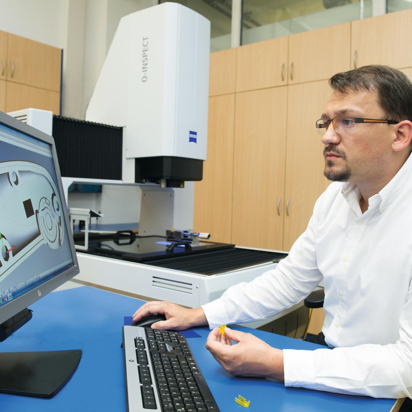
Every lifter should ship with a CMM report citing positional tolerance, perpendicularity and surface profile per ASME Y14.5. XUXIANG’s ZEISS MICURA measures to 0.7 µm and Nikon toolmaker’s microscopes (V-12B / MM-400 class) verify edge geometry.
Red flag: suppliers offering only caliper data or PDF drawings without measured values. Without GD&T verification, you inherit mold-trial risk and potential scrap cost.
Confirm Heat-Treatment Process Control
Ask whether hardening, tempering and nitriding occur in-house or are subcontracted. In-house heat treatment shortens lead time by 3–5 days and ensures traceability. Request hardness-test certificates (HRC or HV) tied to batch lot numbers and material spectral analysis.
Vague ‘heat-treated steel’ claims without furnace records or hardness maps indicate outsourced, uncontrolled processing — a common source of dimensional shift and premature wear.
Audit Quality Certifications and Lead Times
ISO 9001:2015 is baseline; IATF 16949 signals automotive-grade process discipline. XUXIANG’s five-step QC flow — material spectral analysis, in-process monitoring, ZEISS/Nikon CMM, surface-integrity checks and FAI documentation — delivers roughly 30% faster turnaround than industry average.
Compare lead times for standard geometries (7–10 days) versus custom lifter profiles (12–18 days). Shops quoting identical timelines for both rarely have flexible capacity or risk delaying your custom work.
8. Common Mistakes Buyers Make When Specifying Lifters
Even micron-precise lifters fail when buyers overlook fundamental design and procurement decisions. Five errors account for the majority of early wear, stuck cores and unplanned downtime — each avoidable with clear specifications and supplier collaboration.
Under-Specifying Slide Clearance
Clearance between the lifter body and mold pocket below 0.02 mm invites metal-to-metal contact and galling, especially in high-cycle production. Specify 0.03–0.05 mm radial clearance and confirm the supplier’s grinding capability can hold +/-0.002 mm positioning to maintain that gap under thermal expansion.
Ignoring Draft Angles on the Part Geometry
Zero or insufficient draft on undercut features forces the lifter to drag across resin during ejection, scoring both surfaces. Require minimum 1–2° draft on all lifter-formed walls and verify DFM feedback before cutting steel.
Wrong Material for Resin Chemistry
Glass-filled nylon and PBT demand hardened SKD61 or H13 at HRC 48–52; soft P20 wears within 50k cycles. Match lifter material to filler type and processing temperature, and add TiN or CrN coating when abrasive content exceeds 30 %.
Failing to Plan for Maintenance
Ordering a single lifter set with no spares guarantees production halts during rework. Procure at least one redundant set and establish a re-coating schedule at 200k–300k cycles to maximize uptime.
9. Steps to Integrate Lifter Components Into Your Mold Design
Successful lifter integration depends on early collaboration between part designers, mold engineers and component suppliers. XUXIANG’s DFM workflow — involving 10+ engineering experts — catches undercut conflicts, cam interference and ejection-stroke mismatches before tooling begins, reducing rework by up to 40%.
Conduct DFM Analysis to Identify Undercuts
Begin by reviewing the part geometry in CAD to map every undercut feature — internal threads, side pockets, snap hooks — that blocks straight ejection. XUXIANG’s team flags draft angles below 1°, wall thickness transitions and ribs that require lifter or slider actuation.
Document each undercut’s depth, angle and surface-finish requirement; this drives lifter stroke, cam angle and EDM electrode strategy. Early DFM feedback saves 2–3 weeks in downstream tooling revisions.
Select Lifter Type, Angle and Travel
Choose between angled-pin, cam-block or hydraulic lifters based on undercut depth and cycle-time targets. Standard cam angles range from 15° to 25°; steeper slopes reduce mold height but increase wear.
Calculate cam travel as undercut depth divided by sine of the cam angle, then add 2–3 mm safety margin. XUXIANG specifies +/-0.002 mm positioning tolerance on slow-wire cam surfaces to ensure repeatable actuation across millions of cycles.
Coordinate Pocket Dimensions and Tolerances
Share lifter envelope drawings — including cam track, heel block and wear-plate pockets — with your mold-base supplier to confirm pocket depth, parallelism and surface finish. Mismatch here causes binding and premature failure.
XUXIANG provides 2D pocket drawings and 3D STEP models with ISO 2768-mH or tighter tolerances, validated on ZEISS MICURA CMM (0.7 µm resolution). Specify coatings — TiN, TiCN or nitriding — and plan witness marks for final assembly alignment checks.
10. Pricing and Cost Structure for Precision Lifter Components
Precision lifter pricing is governed by four primary cost drivers: material specification (H13 versus SKD61 or NAK80), machining complexity (standard angled versus compound-angle geometry), inspection protocol (CMM validation versus manual checks), and coating selection (nitride, PVD or DLC). A standard angled lifter in H13 at prototype quantities typically ranges USD 180–320 per piece, while compound-angle or micro-lifter designs add 40–70% due to multi-axis wire-EDM time and tighter corner-radius requirements.
Volume discounts follow predictable thresholds: single-piece prototypes carry full setup cost; 10-piece pilot runs amortize tooling over the batch and reduce per-unit cost by roughly 25–35%; production orders of 50+ pieces unlock bulk material pricing and optimized CNC sequencing, driving unit cost down an additional 20–30%. Lead times compress in parallel—prototype lifters ship in 7–10 days, pilot batches in 10–14 days, and production runs in 12–18 days depending on coating queue.
Coating add-ons are priced per component: nitriding adds USD 15–25, TiN/TiAlN PVD USD 20–35, and DLC USD 30–50. Buyers should request itemized quotes that separate base machining, heat treatment, coating and inspection to benchmark supplier transparency and negotiate effectively.
| Lifter Type & Quantity | Unit Price (USD) | Coating Add-On (USD) | Lead Time (Days) |
|---|---|---|---|
| Standard angled lifter (1 pc prototype) | 180–320 | +15–50 | 7–10 |
| Standard angled lifter (10 pc pilot) | 125–225 | +15–50 | 10–14 |
| Standard angled lifter (50+ pc production) | 90–160 | +15–50 | 12–18 |
| Compound-angle lifter (10 pc pilot) | 220–380 | +20–50 | 12–16 |
| Micro-lifter (<5 mm feature, 10 pc) | 280–450 | +25–50 | 14–18 |
Request Your Precision Lifter Quote — 24-Hour Turnaround
Upload your CAD files or technical drawings today. Our engineering team will deliver a detailed quote within 24 hours, with samples ready in 3-7 days.