
Precision Punch Mold Components — Micron-Stable Tooling for Electronics & Automotive
ISO 9001:2015 certified punch mold components machined to +/-0.001 mm with ZEISS CMM validation, Sodick EDM and 24-hour quotes — trusted by OEM/ODM buyers worldwide.
Featured Punch Mold Components
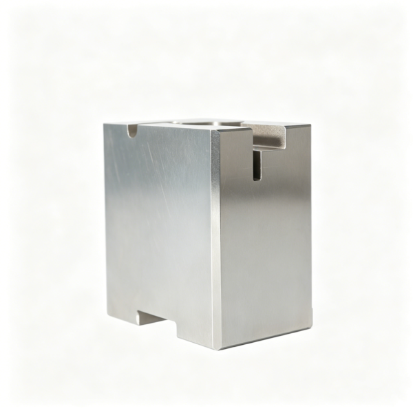
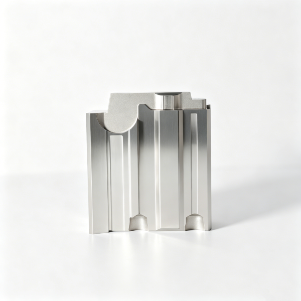
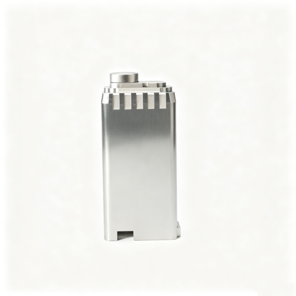
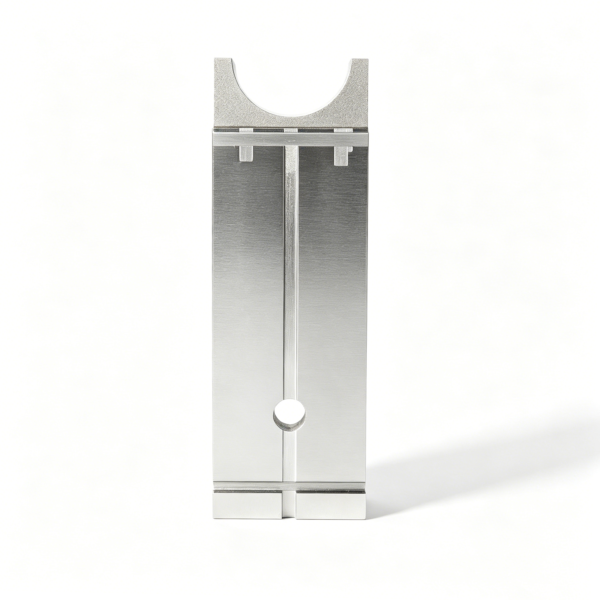
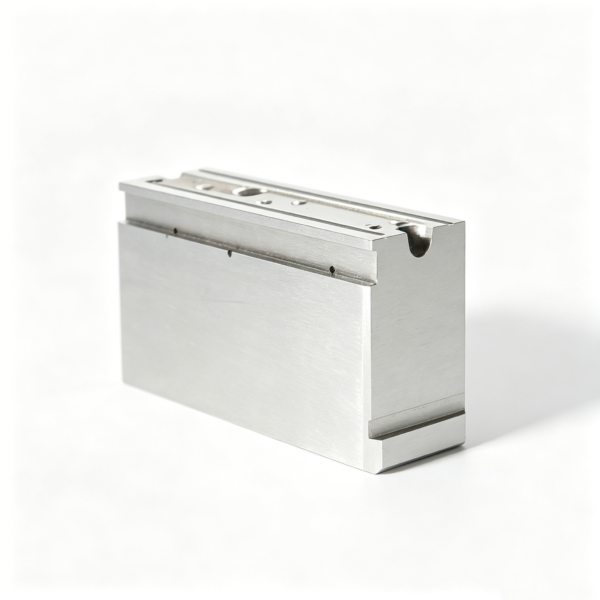
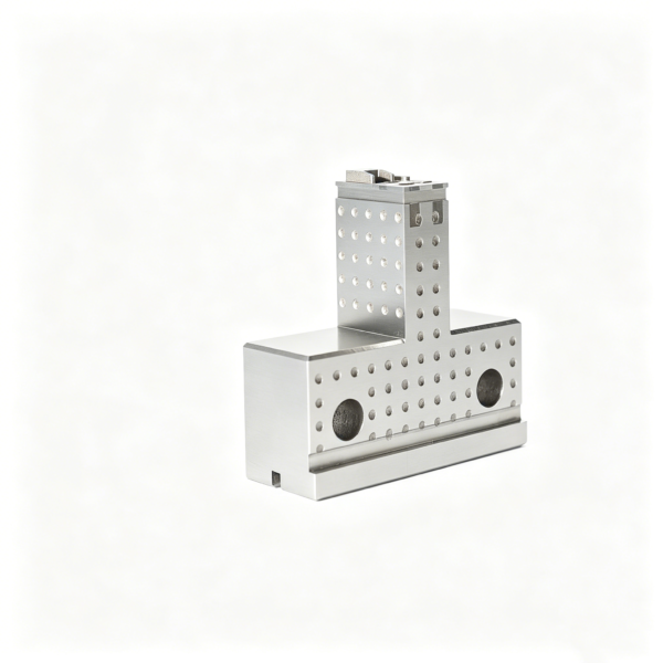
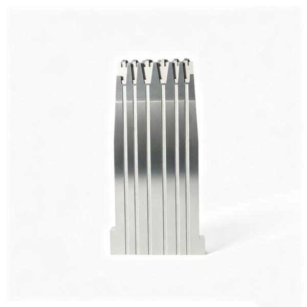
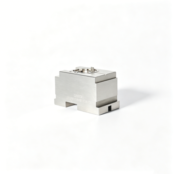
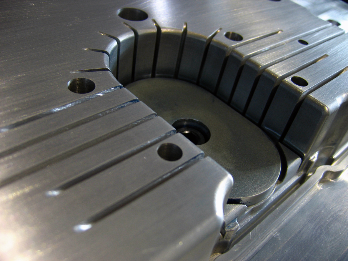
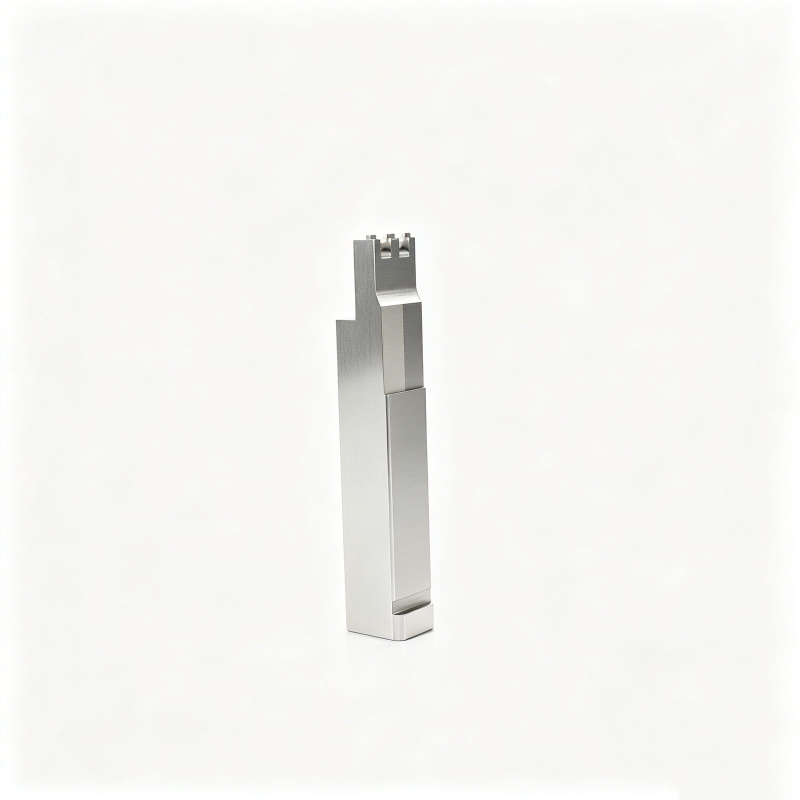
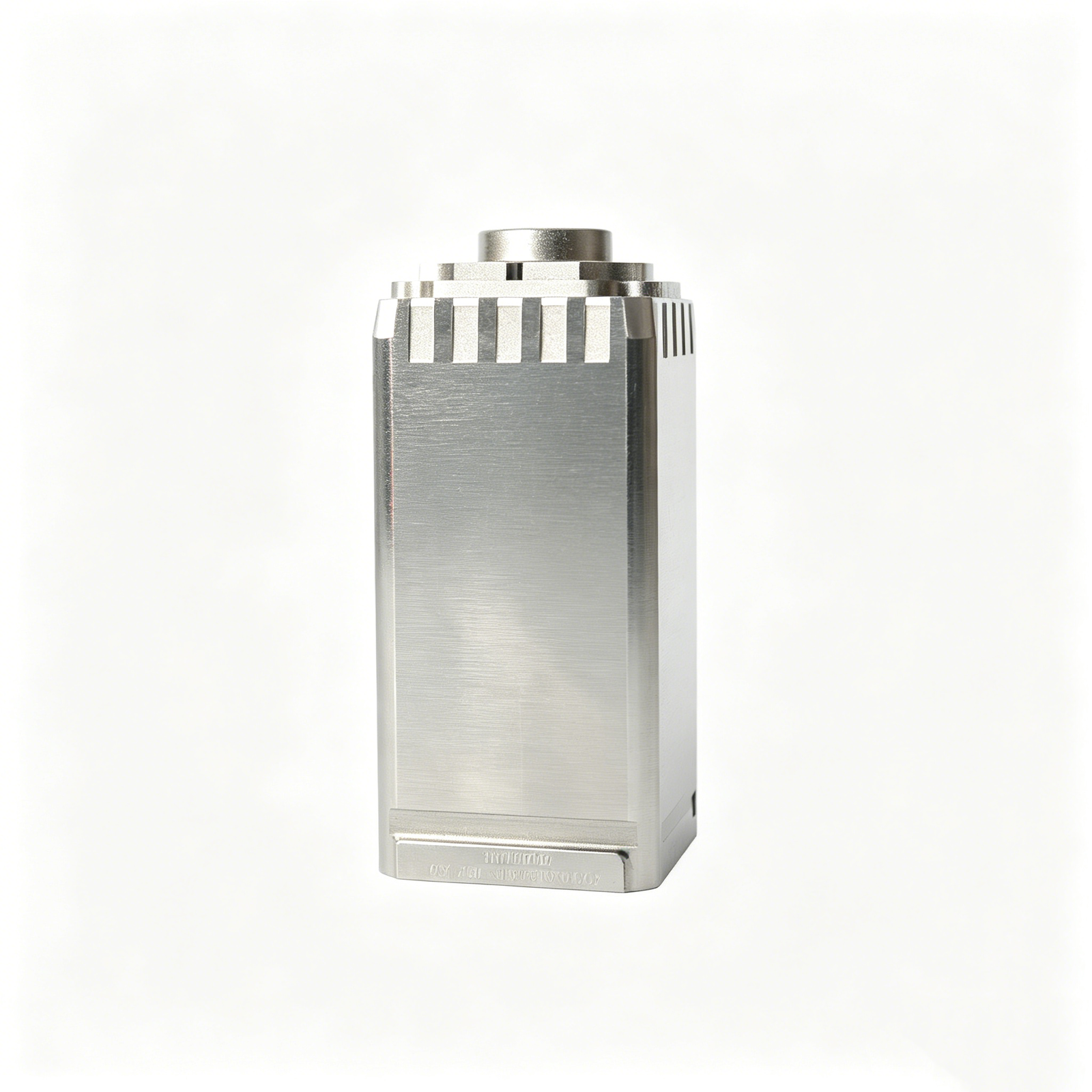
Product Gallery & Sample Showcase
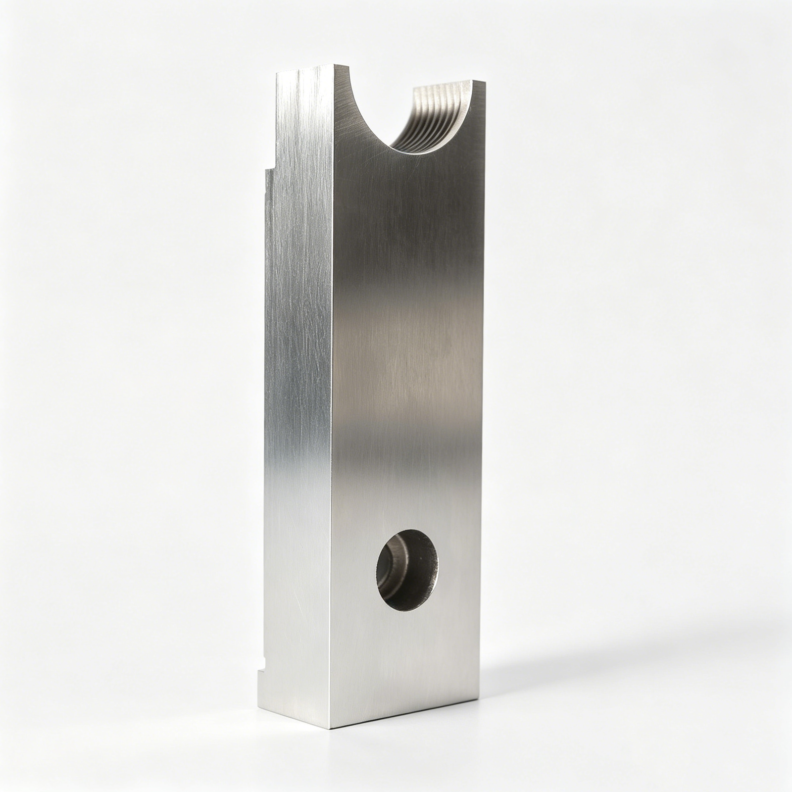
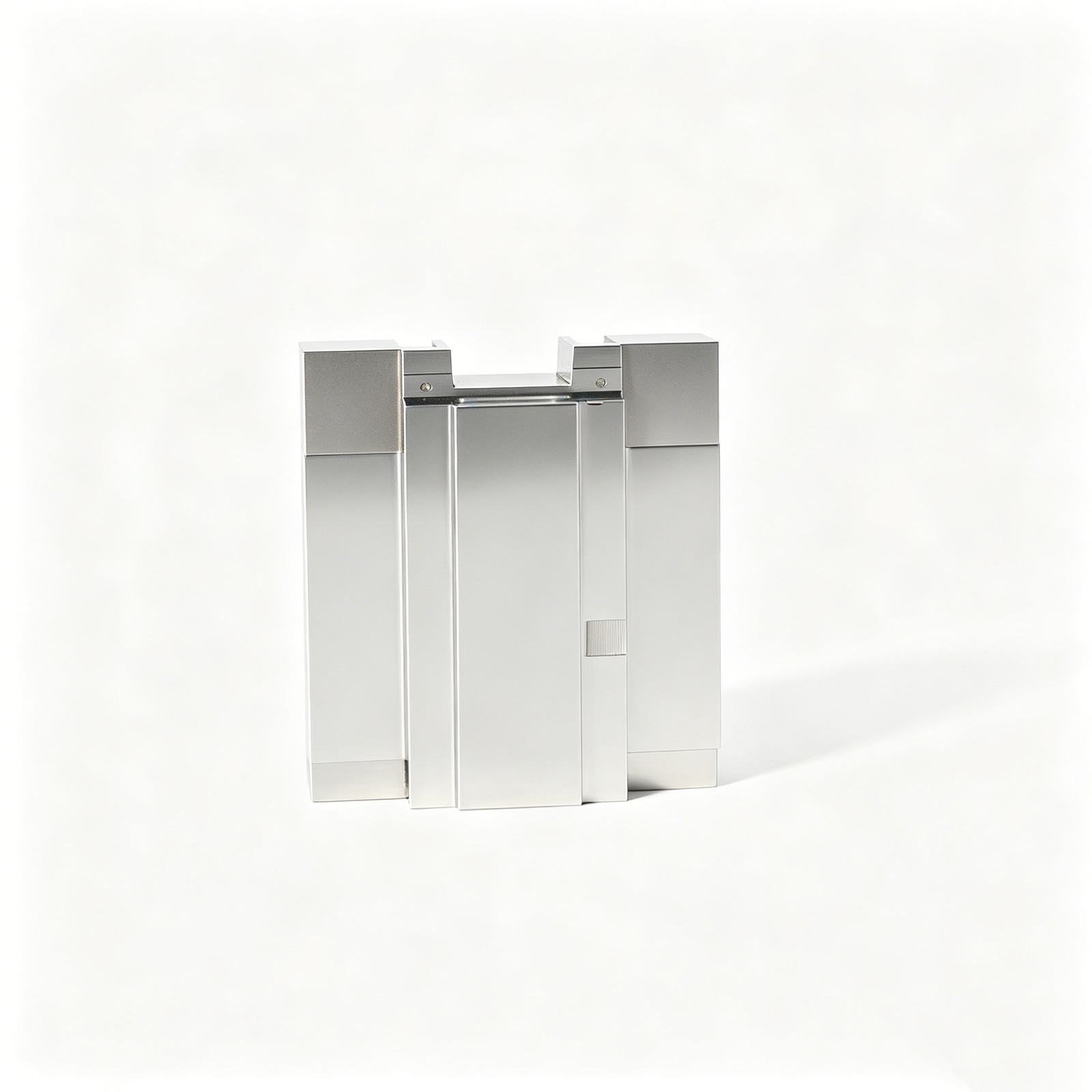
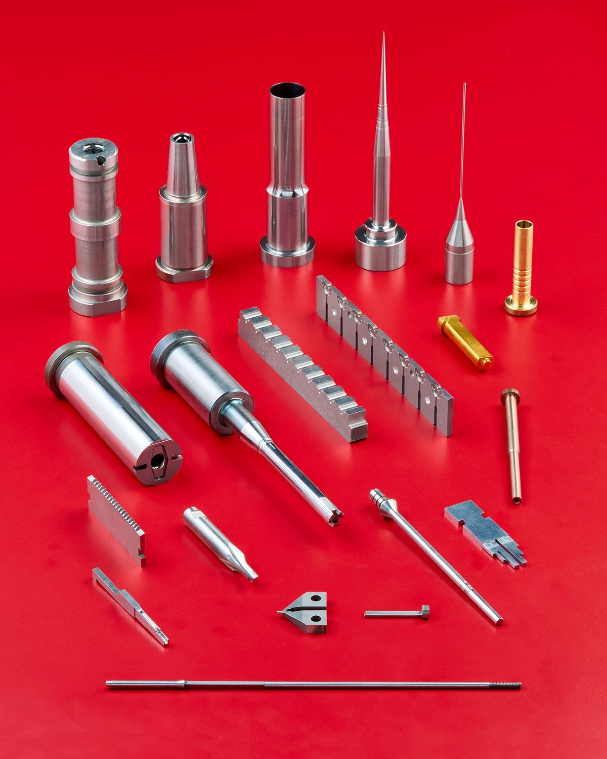
Why XUXIANG Delivers Micron-Stable Punch Mold Components
+/-0.001 mm Machining Precision
Micron-stable accuracy on every punch mold component, verified by ZEISS MICURA CMM and Nikon toolmaker’s microscopes for guaranteed dimensional integrity.
24-Hour Quote Turnaround
Upload your CAD files and receive a detailed quotation within 24 hours, with DFM feedback from our 10+ engineering experts included.
Dual-Factory Volume Capacity
2,000 m² Dongguan micro-machining facility plus 1,400 m² Quanzhou production expansion delivering 200% greater output since 2025 for scalable orders.
ZEISS & Nikon Metrology Lab
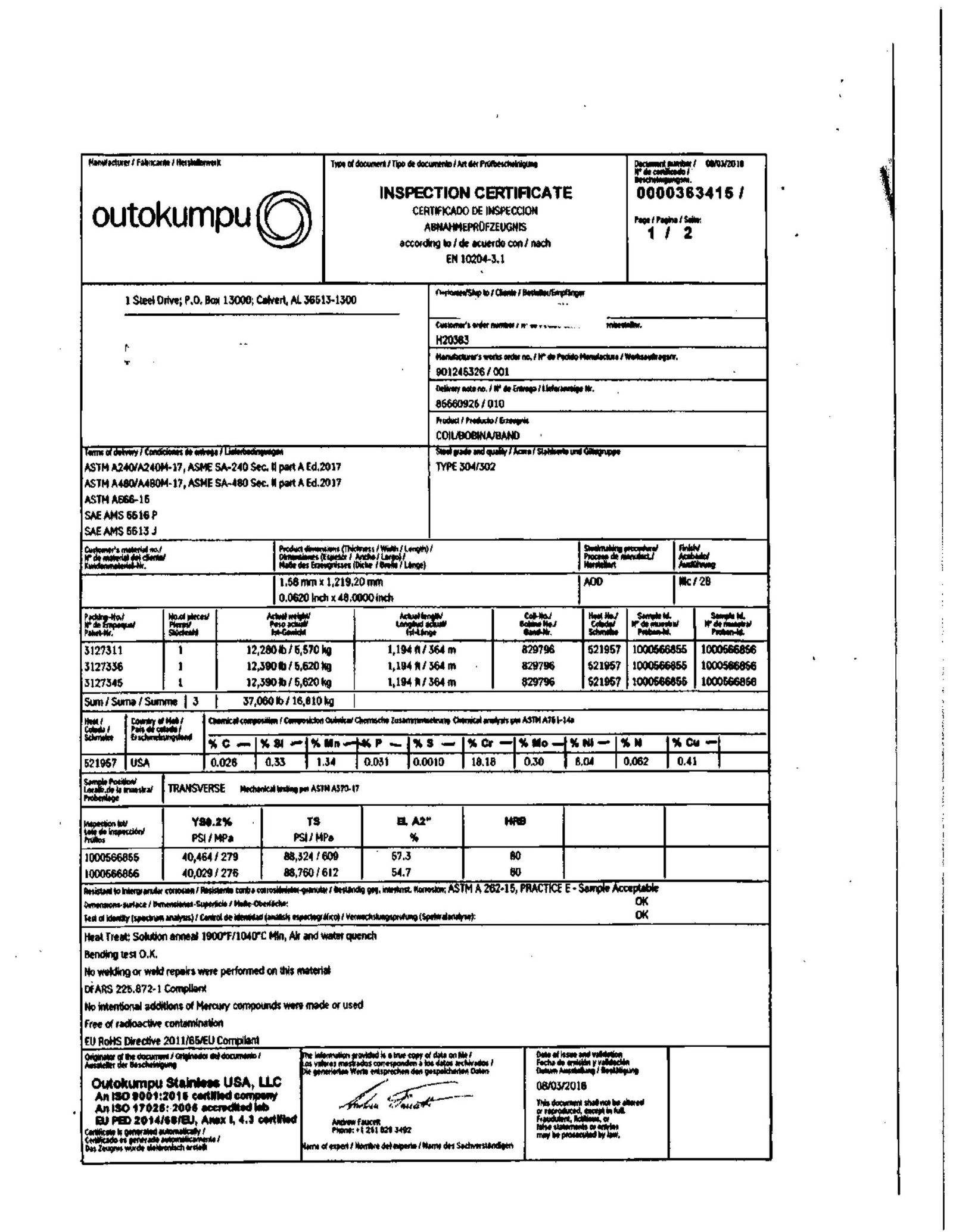
Every punch mold component validated to 0.7um resolution with full FAI reports, material certificates and spectral analysis documentation for traceability.
Sodick & Mitsubishi EDM Fleet
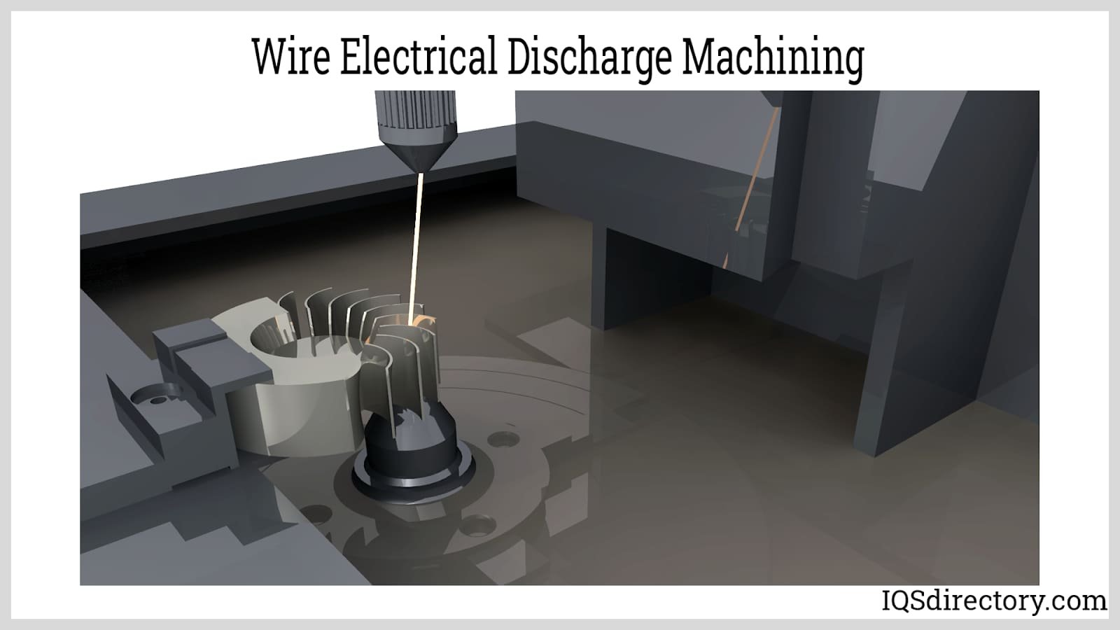
Mirror-grade Ra 0.1um surface finishes and +/-0.002 mm slow-wire tolerances using Japanese Sodick, Seibu and Mitsubishi mirror EDM systems.
16 Years of Tooling Expertise
ISO 9001:2015 certified since 2010, serving electronics, 5G, automotive, NEV and medical-device OEMs with proven precision and dependable delivery performance.
Punch Mold Components & Tooling Solutions
Micron-stable spare parts for plastic injection, stamping dies and micro-connector tooling — machined to +/-0.001 mm, validated with ZEISS CMM and shipped with full FAI documentation.
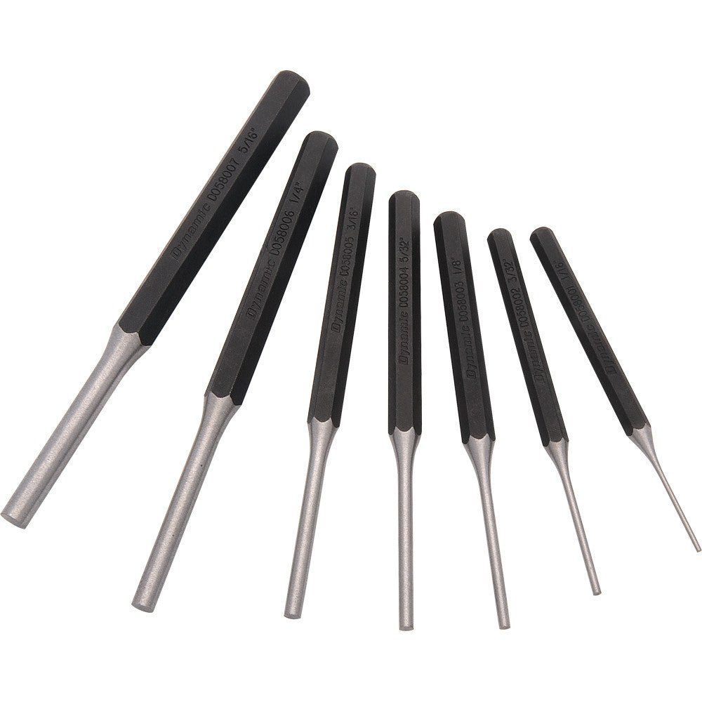
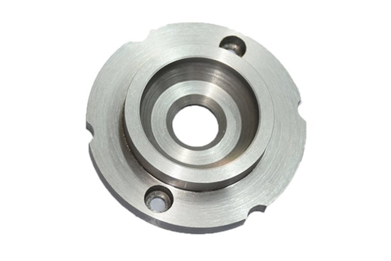
Punch Pins
High-precision punch pins for stamping dies and progressive tooling, machined from SKD11, SKH51 or tungsten carbide to +/-0.001 mm diameter tolerance. Slow-wire EDM and precision grinding ensure perpendicularity within 0.002 mm over length, with optional TiN or DLC coating for wear resistance in high-cycle automotive and connector terminal applications.
Get a Quote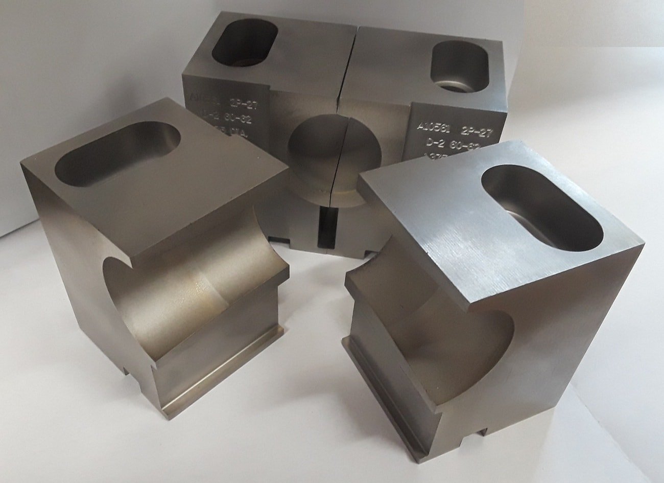
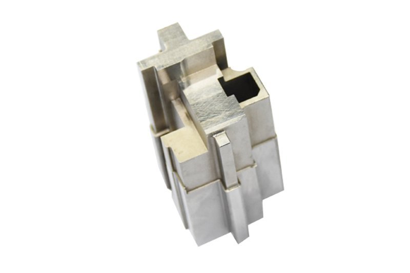
Die Inserts
Custom die inserts for plastic injection molds and metal stamping tools, fabricated via Sodick slow-wire EDM and mirror EDM to Ra 0.1 µm surface finish. Holds +/-0.002 mm positional accuracy across multi-cavity arrays. Material options include NAK80, S136, SKD61 and hardened tool steels, validated with ZEISS MICURA CMM and supplied with material certificates.
Get a Quote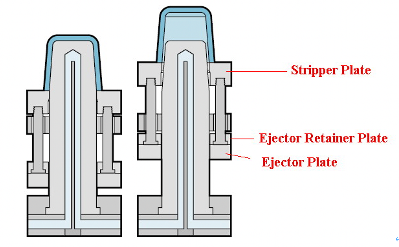
Stripper Plates
Precision-ground stripper plates for progressive dies and fine-blanking tooling, machined flat within 0.003 mm across the working surface. Manufactured from pre-hardened or heat-treated alloy steels with clearance holes positioned to +/-0.005 mm. Ideal for high-speed stamping in automotive terminals, micro-connectors and electronics lead frames requiring cycle stability beyond 500,000 strokes.
Get a Quote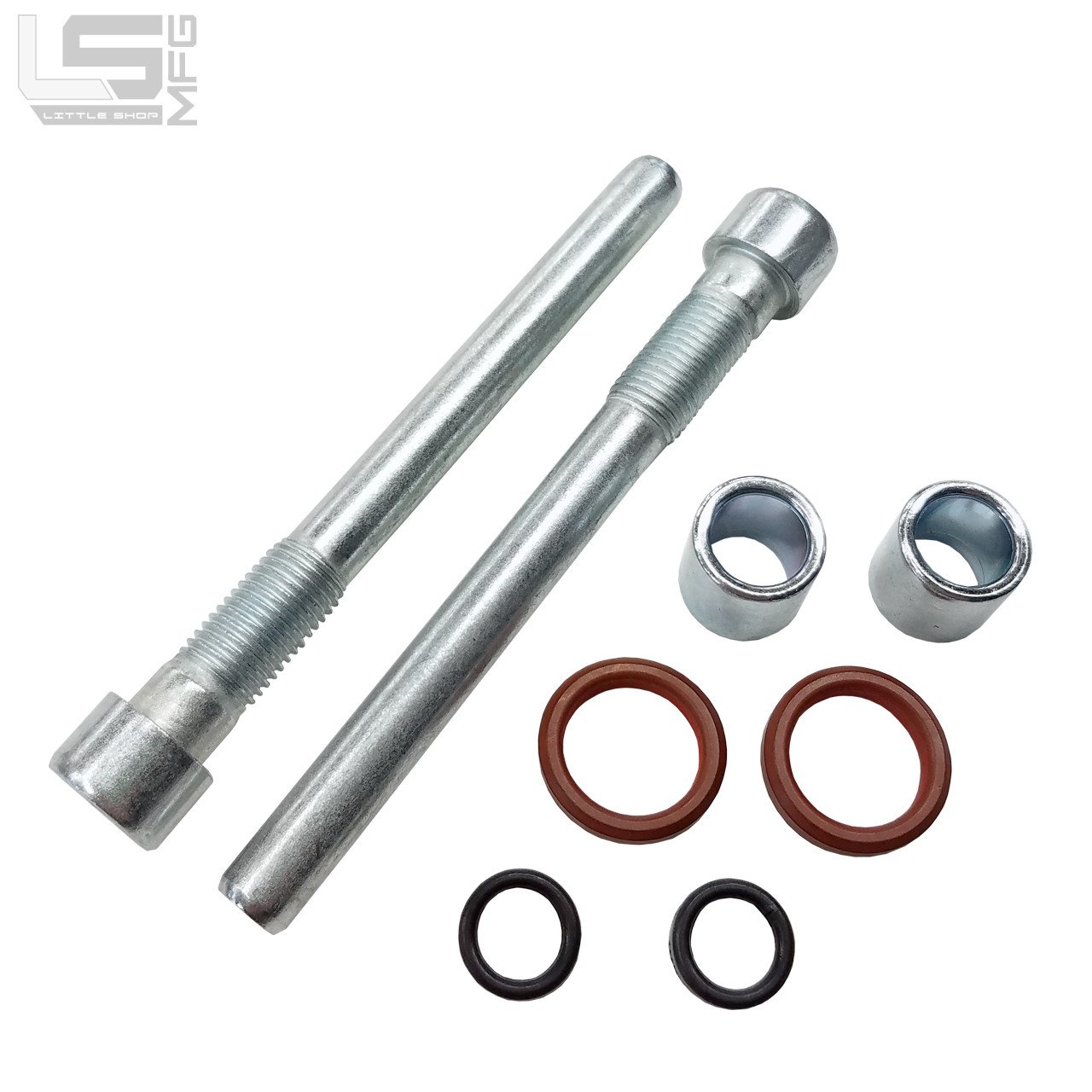
Guide Pins & Bushings
Ground and honed guide pins with matching bronze or hardened-steel bushings, held to +/-0.002 mm diameter tolerance and Ra 0.2 µm finish. Ensures repeatable alignment in injection molds, stamping dies and assembly fixtures. Available in shoulder, headless and flange configurations, with optional surface treatments for corrosive or high-temperature environments in medical-device and automotive tooling.
Get a Quote
Ejector Pins
Standard and custom ejector pins for plastic injection molds, precision-ground to +/-0.003 mm diameter and straightness within 0.005 mm over length. Materials include SKD61, SKH51 and nitrided alloy steels. Suitable for multi-cavity electronics housings, automotive interior parts and thin-wall micro-connector molds where consistent ejection force and minimal flash are critical to part quality and cycle time.
Get a Quote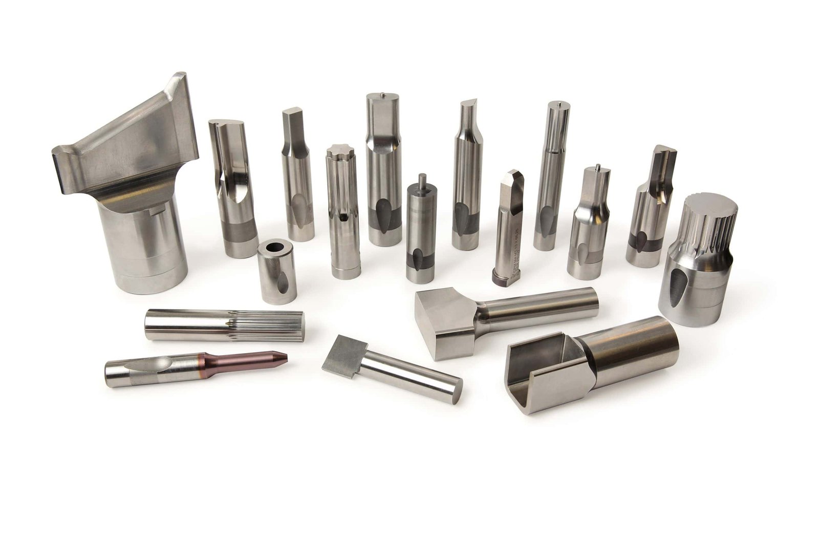
Punch Retainers
Machined punch retainers and backing blocks for progressive and compound dies, ensuring secure punch alignment and load distribution. CNC-milled from S50C, S55C or pre-hardened steels with hole-pattern tolerances of +/-0.01 mm. Designed to reduce punch deflection and extend tool life in high-volume automotive stamping, terminal manufacturing and appliance-component production.
Get a Quote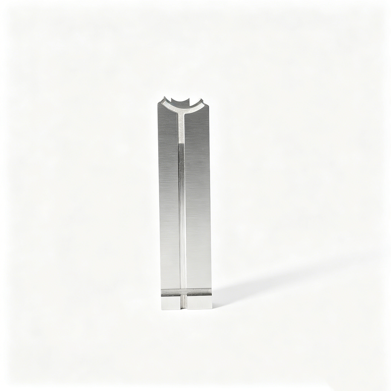
Die Buttons
Precision die buttons in standard and custom diameters, slow-wire EDM-cut and ground to +/-0.002 mm for drop-in replacement or new-tool integration. Available in SKD11, tungsten carbide and ceramic materials. Used in blanking, piercing and forming operations for micro-terminals, sensor brackets and fine-pitch connector shells where edge sharpness and dimensional stability directly impact scrap rate and yield.
Get a Quote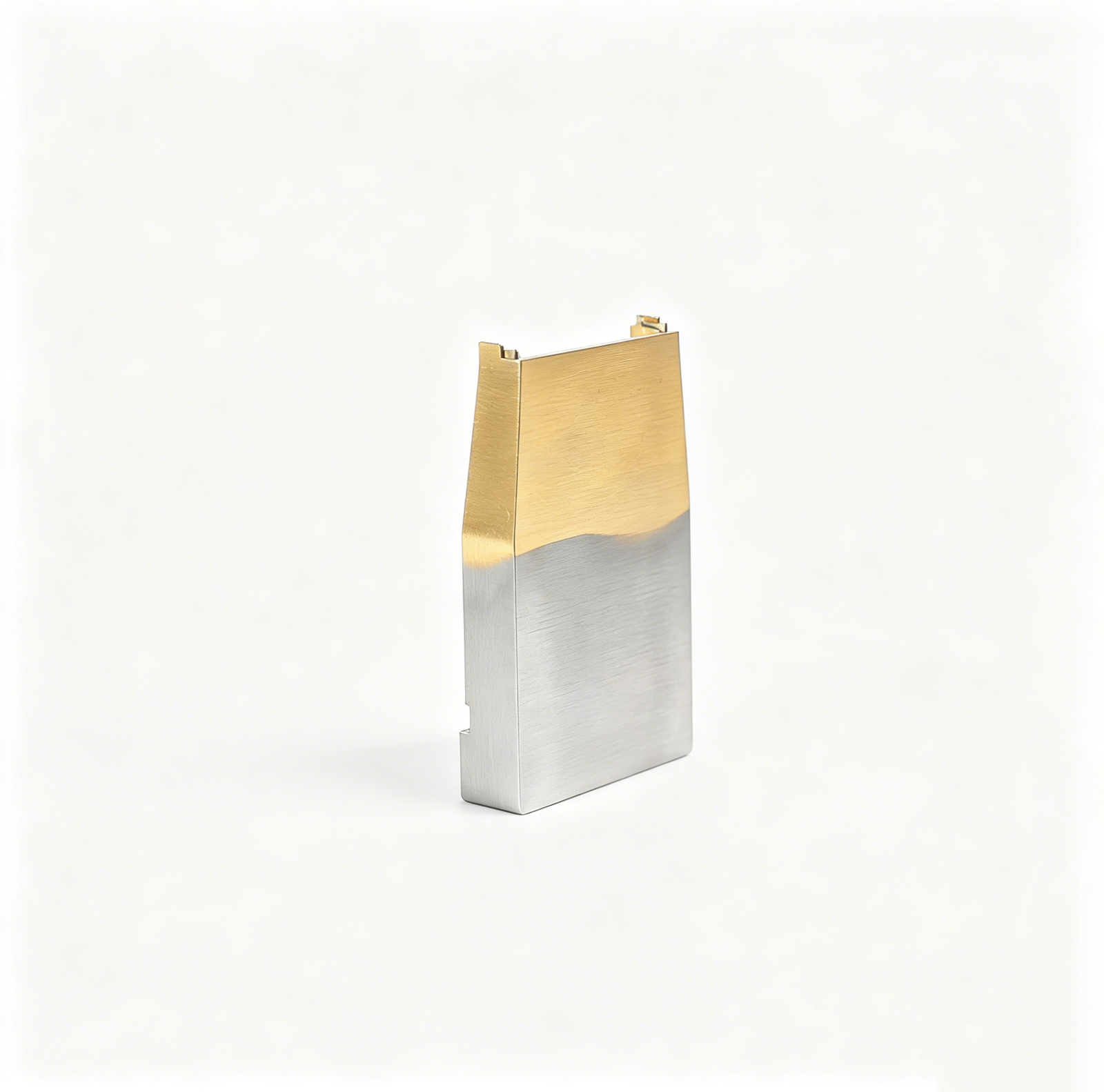
Backing Plates
Flat-ground backing plates for injection molds and stamping dies, machined from S50C, S55C or pre-hardened P20 steel with flatness held to 0.005 mm across the mounting surface. Provides rigid support for cavity inserts, core assemblies and punch modules. Suitable for mid-to-high-tonnage presses and large-format molds in automotive, appliance and industrial-automation applications requiring long-term dimensional stability.
Get a Quote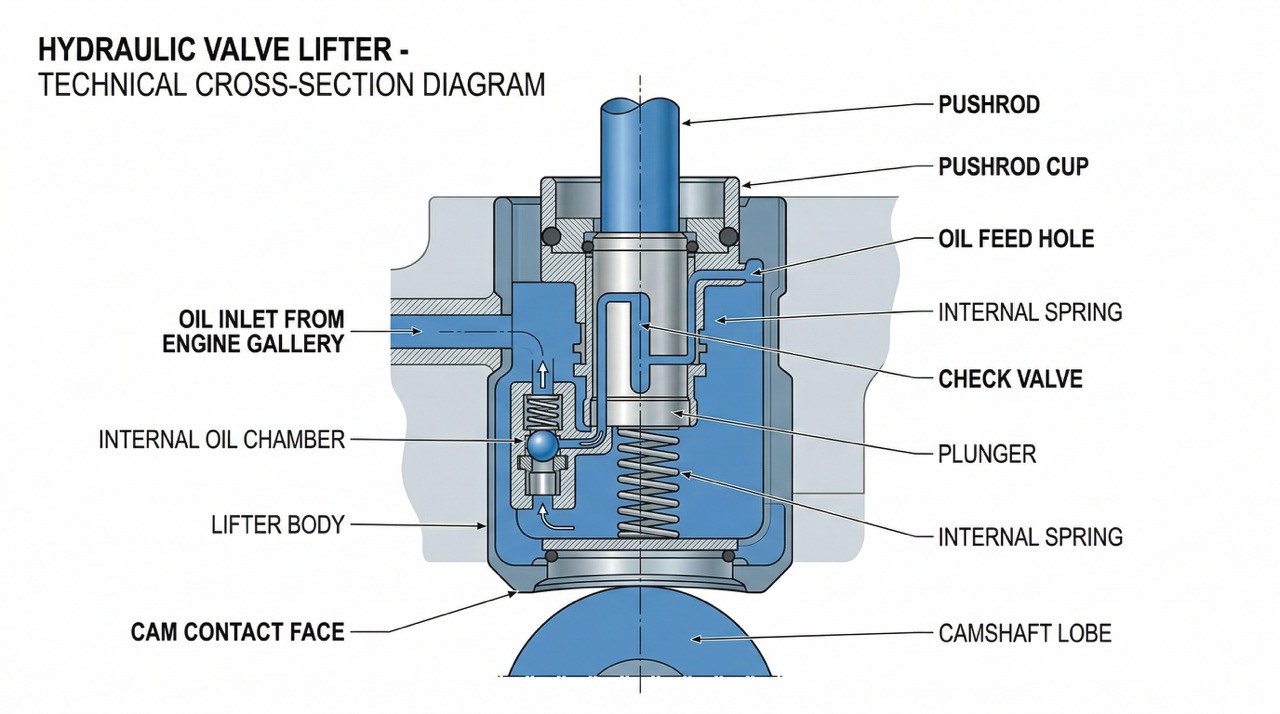
Lifter Components
Custom lifter components including angled lifter blocks, slide cores and cam pins for injection molds with undercut features. Machined to +/-0.003 mm on mating surfaces via CNC and slow-wire EDM, with hardness up to HRC 52–58. Enables reliable actuation in multi-cavity automotive interior molds, electronics enclosures and medical-device housings where side-action precision affects parting-line quality and tool maintenance intervals.
Get a QuoteMaterials We Machine for Punch Mold Components
Precision Machining & EDM Processes for Punch Mold Components

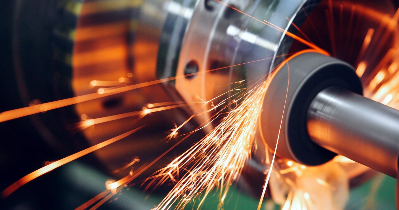
Mirror EDM
Mitsubishi mirror-grade sinker EDM achieves Ra 0.1um surface finishes and +/-0.003 mm tolerance on deep cavities, micro-pins and connector tooling — eliminating secondary polishing while ensuring optical-quality surfaces for demanding electronics and automotive punch mold components.
Electrode Fabrication
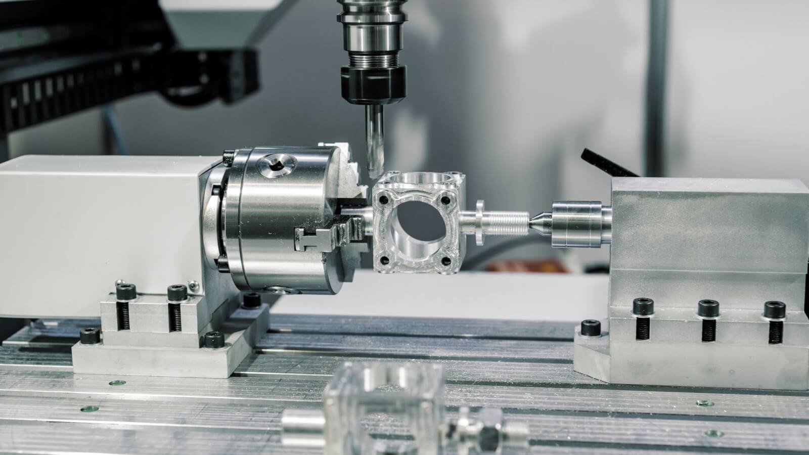
Beijing Jingdiao high-precision CNC electrode machines produce copper and graphite electrodes with micron-level accuracy, enabling complex EDM cavities, sharp internal corners down to R 0.015 mm and consistent spark-gap control for repeatable punch mold component quality.
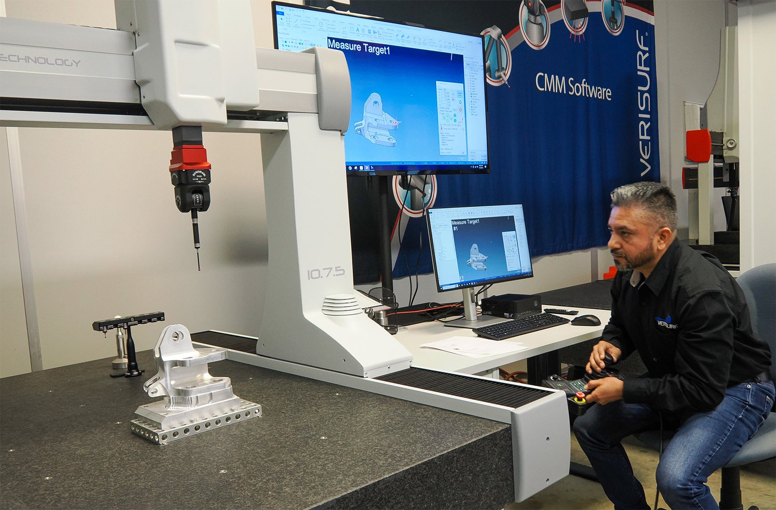
CMM Metrology
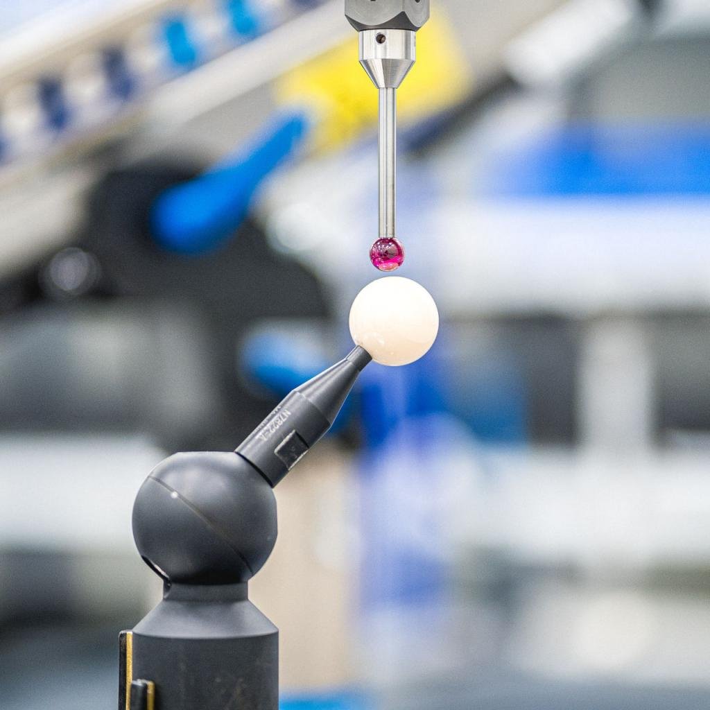
ZEISS MICURA coordinate measuring machine validates every critical dimension to 0.7um resolution, supported by Nikon toolmaker’s microscopes — providing full FAI documentation, material certificates and traceable quality assurance for every punch mold component shipment.
Finishing & Assembly Options for Punch Mold Components
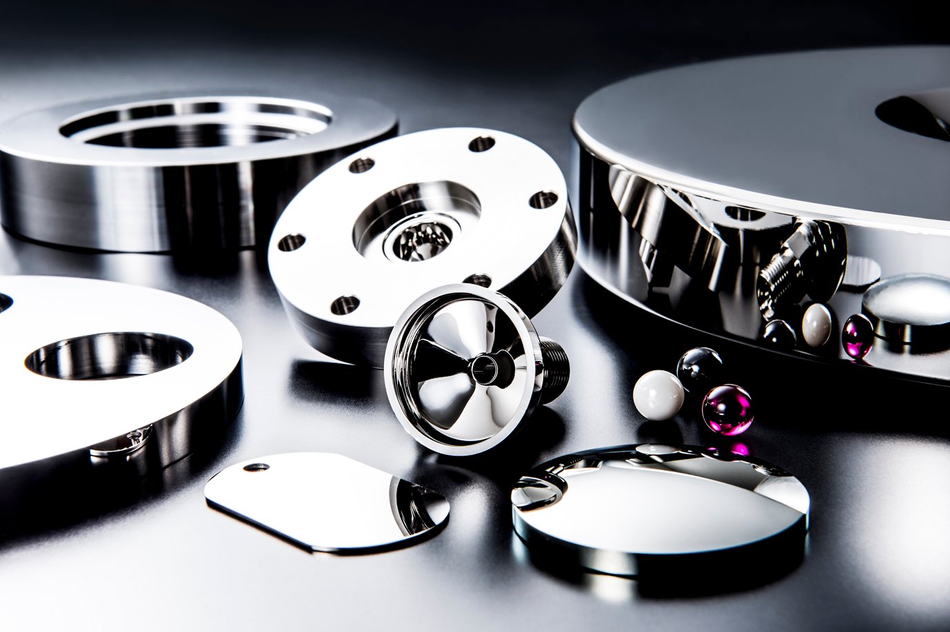
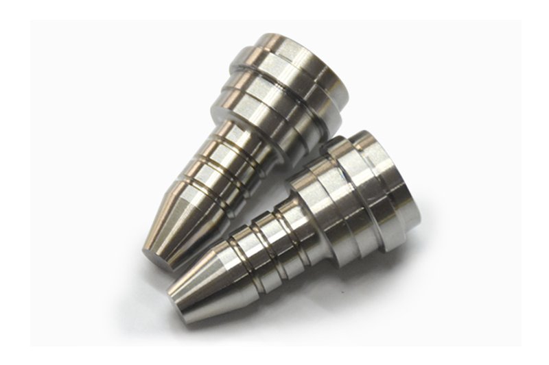
Mirror Polishing
Ra 0.1 µm mirror-grade EDM and mechanical polishing on punch faces and cavities, eliminating post-machining hand work and ensuring flawless part ejection in high-volume stamping and forming operations.
PVD & DLC Coating
Titanium nitride, chromium nitride and diamond-like carbon coatings applied to extend punch life by 300–500%, reduce friction and prevent galling in abrasive or high-speed stamping of stainless steel and hardened alloys.
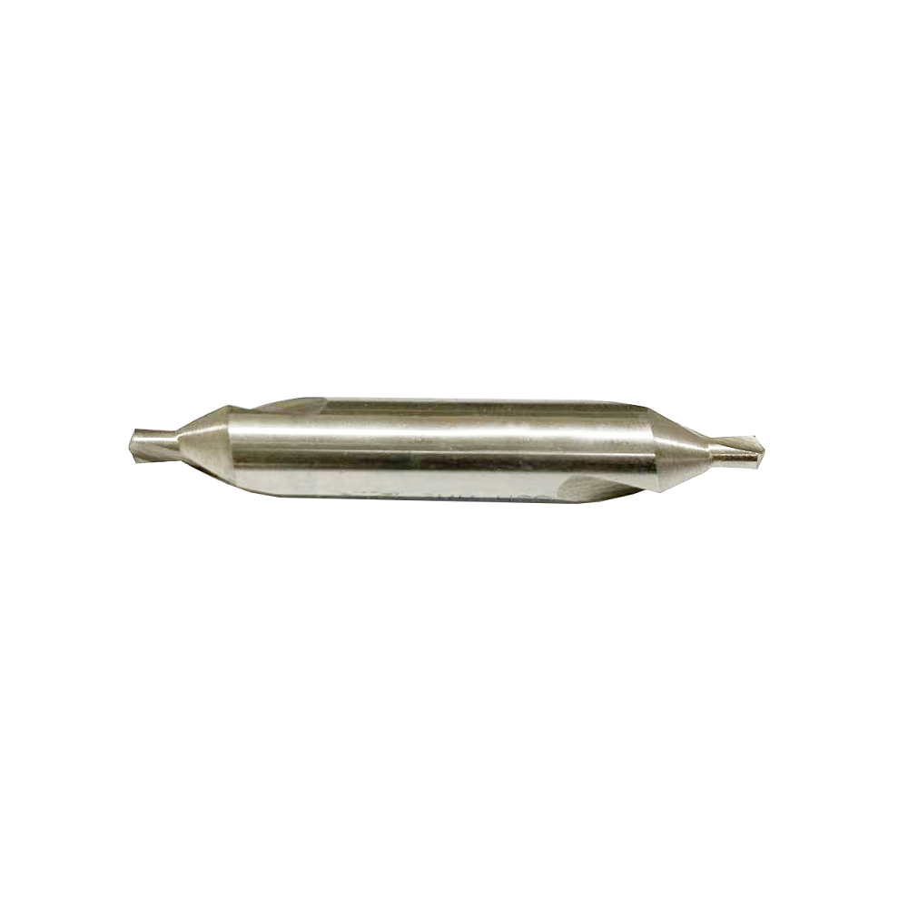
Sub-Assembly & Fit Testing
Pre-assembled punch sets with guide bushings, retainers and springs, fit-tested to your die plate specifications, delivered as drop-in modules that cut your tool-room setup time by up to 40%.
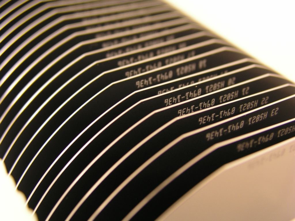
Laser Marking & Serialization
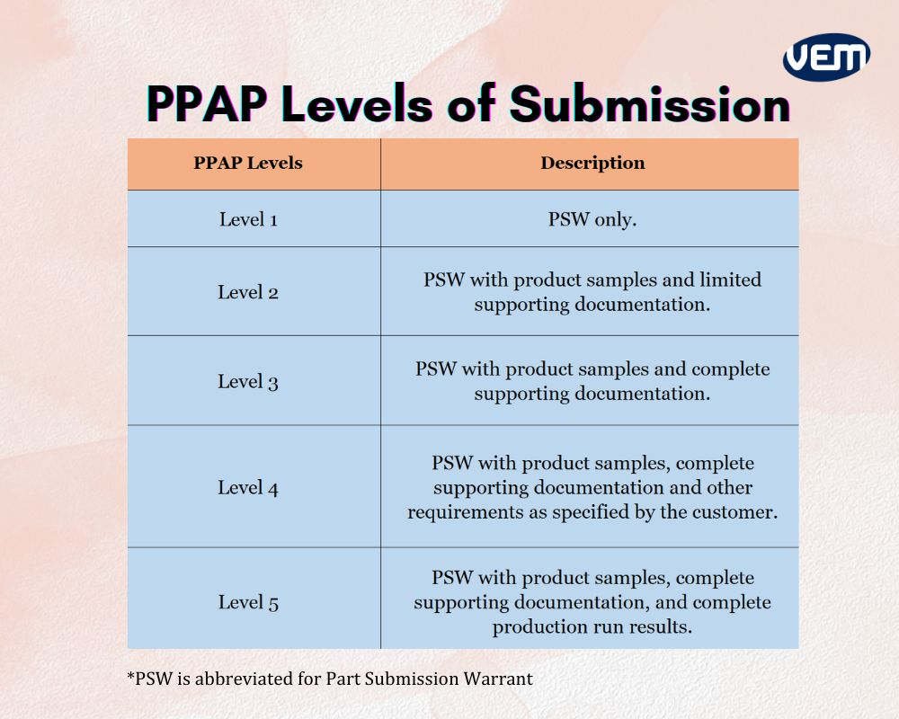
Permanent fiber-laser engraving of part numbers, revision codes and serial identifiers for traceability, inventory control and compliance with automotive PPAP and medical-device DHF requirements.


Full FAI Documentation
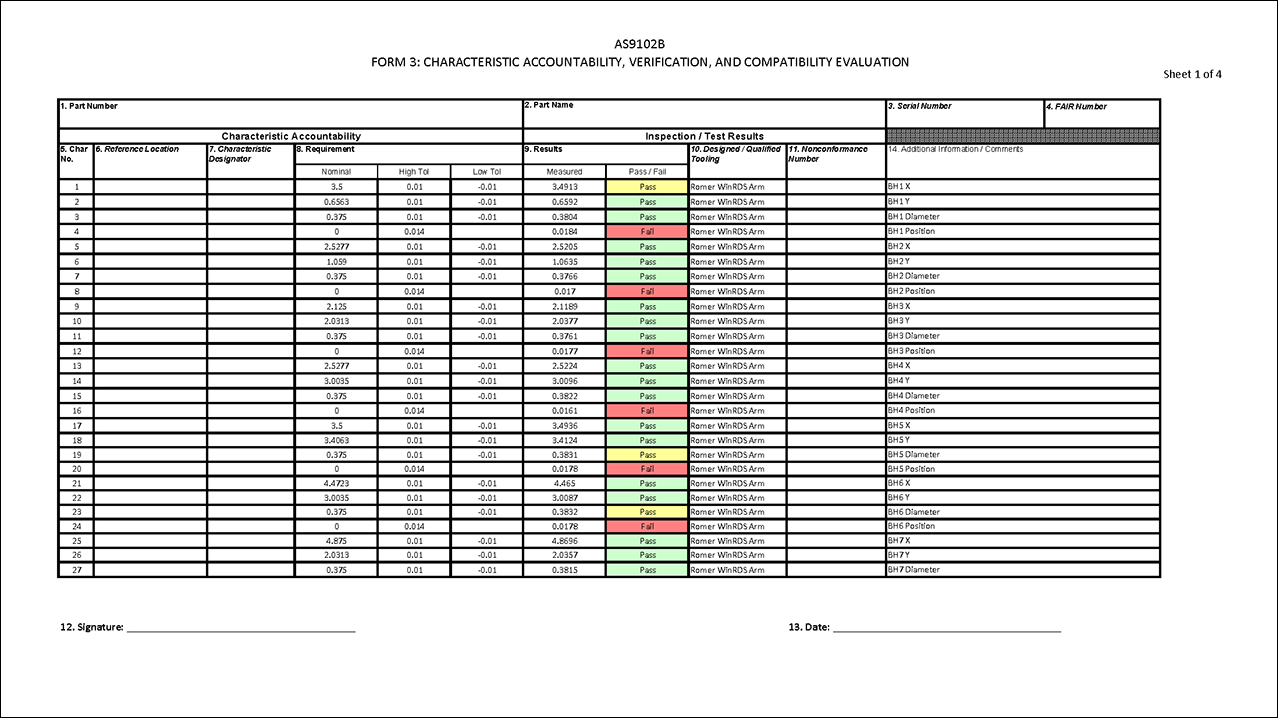
First-article inspection reports with ZEISS CMM dimensional data, material certificates, surface-finish readings and photographic evidence — ready for PPAP submission, AS9102 or ISO 13485 audit trails.
About XUXIANG — 16 Years of Precision Punch Mold Components
Founded in 2010 in Dongguan’s Chang’an manufacturing hub, XUXIANG began as a specialist mold-core machining shop and has evolved into a full-service precision manufacturer supplying electronics, 5G/telecom, automotive & NEV, industrial-automation and medical-device customers worldwide. Our mission: bridge the gap between complex CAD designs and high-performance physical parts with micron-stable precision.
Today we operate dual factories — a 2,000 m² Dongguan facility for R&D and micro-machining, plus a 1,400 m² Quanzhou expansion launched in 2025 that boosts annual capacity by 200%. Over CNY 8 million invested in Japanese Sodick slow-wire EDM, Swiss Charmilles sinker EDM, German ZEISS MICURA CMM and Fanuc CNC systems ensures +/-0.001 mm machining accuracy and Ra 0.1um mirror-grade finishes.
ISO 9001:2015 governs every process. A team of 10+ DFM engineers reviews each project before production, and every shipment includes full FAI reports with material certificates. We deliver samples in 3–7 days, mass production in 15–25 days, and quotes within 24 hours — roughly 30% faster than the industry average.
Precision Punch Mold Components: Engineering & Manufacturing Deep Dive
Micron-Stable CNC & EDM Machining
XUXIANG holds +/-0.001 mm machining precision across every punch mold component using Sodick slow-wire EDM, Mitsubishi mirror EDM and Fanuc CNC — delivering mirror-grade Ra 0.1um surface finishes and corner radii down to R 0.015 mm for high-density connector tooling and automotive sensor housings.
- Sodick & Seibu slow-wire EDM achieving +/-0.002 mm class positioning on intricate geometries
- Mitsubishi mirror EDM producing Ra 0.1um finishes without secondary polishing
- Beijing Jingdiao high-precision CNC for electrode fabrication and micro-feature machining
- Dawn precision grinding centers maintaining flatness and parallelism within 0.003 mm
ZEISS MICURA CMM Metrology Validation
Every punch mold component undergoes full-dimensional verification on our ZEISS MICURA coordinate measuring machine with 0.7um repeatability, supported by Nikon V-12B and MM-400 class toolmaker’s microscopes — ensuring that critical features meet your print before shipment, with complete FAI documentation and material certificates included.
- ZEISS MICURA CMM measuring to 0.7um for true micron-level validation
- Nikon toolmaker's microscopes for edge-break, surface-integrity and micro-feature inspection
- Five-step QC flow: material spectral analysis, in-process monitoring, CMM verification, surface checks, final FAI
- Full first-article inspection reports and certified material test certificates with every order
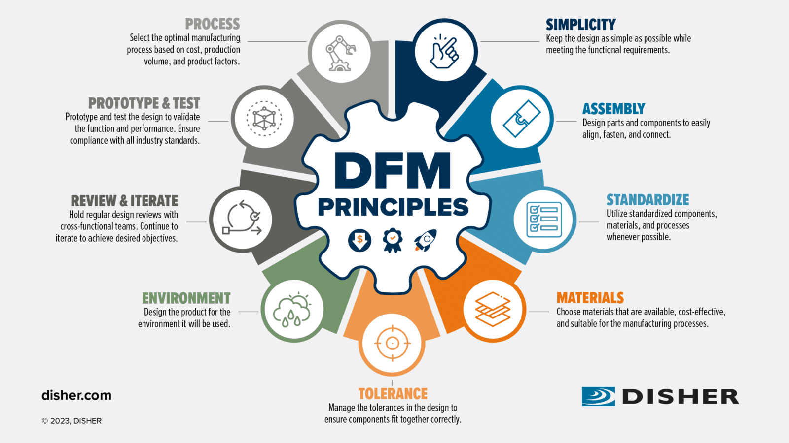
DFM Engineering & Design Support
Before any punch mold component enters production, our team of 10+ engineering experts reviews your CAD files for manufacturability, tolerance stack-up, tool-path optimization and potential cost savings — delivering actionable DFM feedback within 24 hours to prevent costly rework and accelerate time-to-market.
- 10+ precision-engineering specialists with 16 years of mold-component experience
- CAD-driven DFM analysis identifying tolerance conflicts, undercuts and machining risks
- Tool-path and electrode-strategy optimization to reduce cycle time by up to 30 percent
- Collaborative design iteration for complex micro-connector and automotive punch tooling
Dual-Factory Capacity & Fast Turnaround
Our 2025 expansion added 1,400 m² of volume-production floor space in Quanzhou, Fujian, lifting annual output by a targeted 200 percent while our Dongguan R&D facility focuses on micro-machining and prototyping — enabling 3–7 day samples and 15–25 day mass production, roughly 30 percent faster than industry average.
- Dongguan 2,000 m² R&D + micro-machining center for high-precision prototypes and complex tooling
- Quanzhou 1,400 m² volume-production facility for scalable punch mold component manufacturing
- Over CNY 8 million invested in Japanese, Swiss, German and domestic precision equipment
- ISO 9001:2015 quality management across both sites with real-time production tracking
Why Choose XUXIANG Punch Mold Components Over Typical Suppliers
Precision tooling demands more than standard machining. Compare our verifiable capabilities against typical mold component suppliers — equipment, tolerances, metrology and delivery commitments that eliminate procurement risk.
← 左右滑动查看 →
How We Manufacture Punch Mold Components to +/-0.001 mm
Every punch mold component moves through our ISO 9001:2015 production flow — from DFM engineering review to ZEISS CMM validation — ensuring micron-stable precision, mirror-grade finishes and full FAI traceability before shipment.
Design Review & DFM
Our 10+ engineering experts analyze your CAD files, flag tolerance risks, recommend material and EDM strategy, and return DFM feedback within 24 hours to prevent costly rework downstream.
Material Prep & CNC Machining
Certified alloys undergo spectral analysis, then rough and finish CNC machining on Fanuc-class centers to +/-0.002 mm, with in-process tolerance monitoring at every operation.
Slow-Wire EDM & Mirror Finishing
Sodick and Seibu slow-wire EDM machines hold +/-0.002 mm positioning and corner radii down to R 0.015 mm; Mitsubishi mirror EDM delivers Ra 0.1 µm surface integrity.
ZEISS CMM Metrology Validation
Every critical dimension is verified on our ZEISS MICURA CMM to 0.7 µm resolution and Nikon toolmaker’s microscopes, with deviation reports logged in our ISO quality database.
Surface Integrity & FAI Documentation
Surface-finish profilometry, hardness checks and final dimensional inspection are completed; full FAI reports, material certificates and inspection images are prepared for your records.
Protective Packing & Expedited Shipping
Components are individually protected, vacuum-sealed or foam-packed to prevent handling damage, then shipped with tracking — samples in three to seven days, production in fifteen to twenty-five days.
How to Partner with XUXIANG for Punch Mold Components
From CAD upload to final delivery, our engineering-led process ensures your punch mold components meet micron-stable tolerances and arrive on time — every time.
Submit CAD & Technical Requirements
Upload your 2D/3D drawings and technical specifications. Our system acknowledges receipt instantly, and a project engineer is assigned within hours to review feasibility.
Receive DFM Feedback & 24-Hour Quote
Within 24 hours, our 10+ engineering experts deliver Design for Manufacturability recommendations, material options, tolerance validation and a transparent, itemized quotation.
Approve Sample & Validate Tolerances
We machine first-article samples in 3–7 days, inspect on ZEISS MICURA CMM and ship with full FAI reports and material certificates for your approval.
Enter Mass Production with QC Monitoring
Once approved, production begins under ISO 9001:2015 controls. Every batch undergoes five-step QC, in-process tolerance monitoring and final CMM verification before shipment.
Receive On-Time Delivery & Documentation
Bulk orders ship in 15–25 days with complete traceability: FAI reports, material certificates, dimensional data and packaging optimized for global logistics.
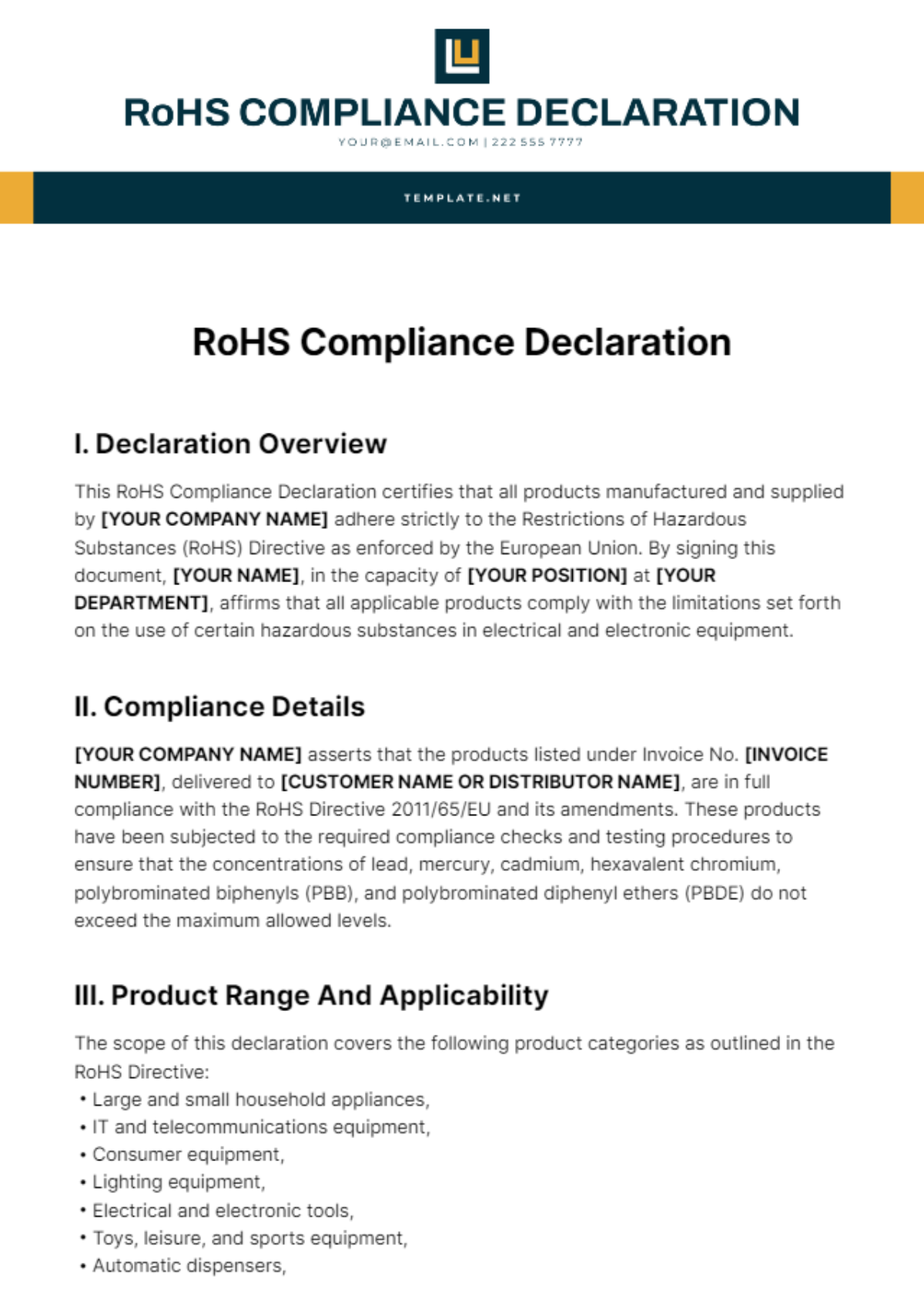
Quality Certifications Backing Every Punch Mold Component

What Our Customers Say About XUXIANG Punch Mold Components
We switched to XUXIANG for automotive sensor punch mold components and achieved +/-0.002 mm repeatability across 50,000 cycles. Lead time dropped from 28 days to 18 days, and zero tolerance failures in six months of production.
Their micro-connector punch tooling held Ra 0.12 µm mirror finish on 0.3 mm pins for our 5G board-to-board assemblies. DFM feedback caught three design risks before production, saving us at least $12,000 in rework and two weeks of delay.
XUXIANG delivered 120 precision punch inserts for our robotic gripper assembly jigs in 16 days with full FAI documentation. ZEISS CMM reports showed every part within +/-0.0015 mm. Their 24-hour quote turnaround is unmatched in Dongguan.
Frequently Asked Questions About Punch Mold Components
What is the minimum order quantity for punch mold components?
How long does it take to receive a quote for punch mold components?
What are the typical lead times for punch mold components?
Do you charge for sampling or first-article inspection of punch mold components?
What materials do you use for punch mold components?
How do you protect intellectual property and confidential designs for punch mold components?
What payment terms do you offer for punch mold components orders?
What kind of post-delivery support do you provide for punch mold components?
Can you guarantee +/-0.001 mm tolerance on all punch mold components?
The Complete Buyer’s Guide to Punch Mold Components for Precision Tooling
Navigate the critical selection criteria for punch mold components with confidence. This guide delivers a proven decision framework, supplier evaluation benchmarks, material comparisons, and the costly mistakes procurement teams must avoid when sourcing micron-precision tooling.
1. What Are Punch Mold Components?
Punch mold components are the precision-machined functional elements that form, guide and eject parts in stamping dies and injection molds. A typical assembly includes punches (male forming tools), dies (female cavities), guide pins and bushings (alignment hardware), retainers (structural plates) and ejector pins (part-release mechanisms). Each component must hold micron-level dimensional stability under cyclic mechanical and thermal loads; a +/-0.002 mm positioning error in a guide pin can cascade into flash, short shots or ejector marks across thousands of cycles.
In electronics and automotive connector tooling, punch mold components enable the high-volume production of micro-pins, terminals and housing inserts where feature sizes drop below 0.5 mm and positional tolerances tighten to +/-0.01 mm or less. Tool life and first-pass yield depend directly on component precision: a mirror-finish EDM punch (Ra ≤ 0.2 µm) paired with a hardened die insert can deliver 500,000+ cycles without rework, whereas poorly matched or undertolerance components trigger scrap rates above 5 % and unplanned downtime every 50,000–100,000 shots.
2. Evolution of Punch Mold Components in Precision Manufacturing
Manual tool-and-die shops dominated punch mold production through the 1980s, holding tolerances around +/-0.05 mm with skilled hand-finishing. The 1990s saw carbide tooling adoption reduce wear rates by 5–10× over high-speed steel, while wire-EDM enabled complex geometries — corner radii below 0.05 mm and taper-free profiles — that grinding alone could not achieve.
By the early 2000s, TiN and TiCN coatings extended punch life 3–4× through reduced friction and oxidation resistance, cutting cost-per-part in high-volume stamping. CNC machining centers with closed-loop feedback brought repeatability into the +/-0.005 mm range, enabling the first generation of high-density mobile connectors.
5G miniaturization after 2015 and NEV battery-management-system interconnect density pushed terminal pitches below 0.6 mm, demanding punch mold components accurate to +/-0.002 mm. Today’s slow-wire EDM and ZEISS CMM metrology — such as XUXIANG’s 0.7um-resolution MICURA platform — routinely validate +/-0.001 mm tolerances, a 50× improvement over manual-era benchmarks.
3. Types of Punch Mold Components and Their Applications
Punch mold components divide into five functional families, each engineered for distinct forming, cutting or alignment tasks. Selection hinges on part geometry, material thickness and production volume — standard catalog items suit high-volume terminals, while custom profiles are mandatory for micro-connector or automotive sensor housings.
Punches: Piercing, Forming and Coining
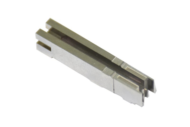
Piercing punches shear holes in strip or sheet; forming punches create bends, embossments or flanges; coining punches impress fine detail under high tonnage. Micro-connector punches for 5G and telecom demand corner radii ≤ R0.015 mm and +/-0.002 mm positional tolerance to avoid pin-socket misalignment.
Custom profiles are required whenever feature pitch drops below 0.5 mm or when the part includes undercuts that standard catalog punches cannot release.
Dies: Cutting and Forming

Cutting dies shear perimeters or blanks; forming dies shape three-dimensional features in a single stroke. Automotive terminal dies often combine both operations in progressive layouts, holding +/-0.003 mm on critical contact zones.
Standard die blocks work for flat blanking; complex bends, draws or multi-level features require custom EDM cavities with mirror finishes down to Ra 0.1 µm to prevent galling.
Guide Components: Pins, Bushings and Pillar Sets
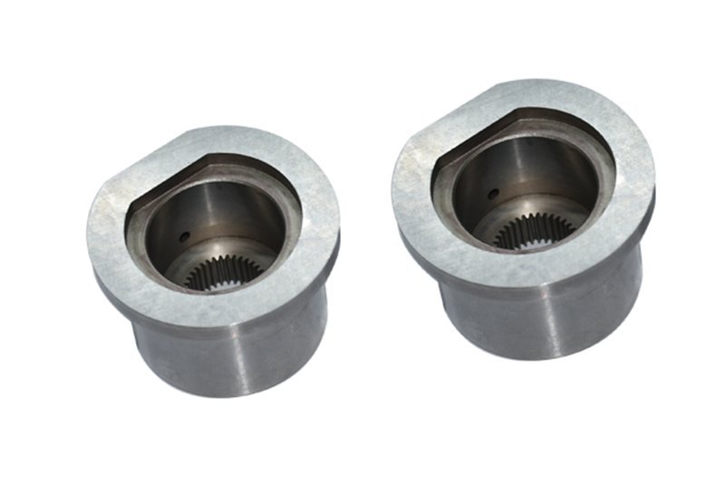
Guide pins and bushings maintain upper-to-lower die alignment within +/-0.005 mm over millions of cycles; pillar sets carry separating forces and set shut height. Misalignment by 0.01 mm doubles punch wear and rejects parts.
Standard catalog pins suit moderate-volume work; high-density micro-tooling and any layout exceeding four stations justify custom-ground pillar sets to hold concentricity ≤ 0.003 mm.
Ejector Systems

Ejector pins, sleeves and springs strip finished parts from punches or cavities without deformation. Thin-wall connector shells (≤ 0.2 mm) require custom ejector geometry and controlled spring rates to avoid buckling.
Standard coil springs and straight pins handle robust stampings; delicate or high-aspect-ratio parts need tailored ejector diameters, surface coatings and stroke limits validated by CMM inspection.
Retainer Plates and Backing Plates
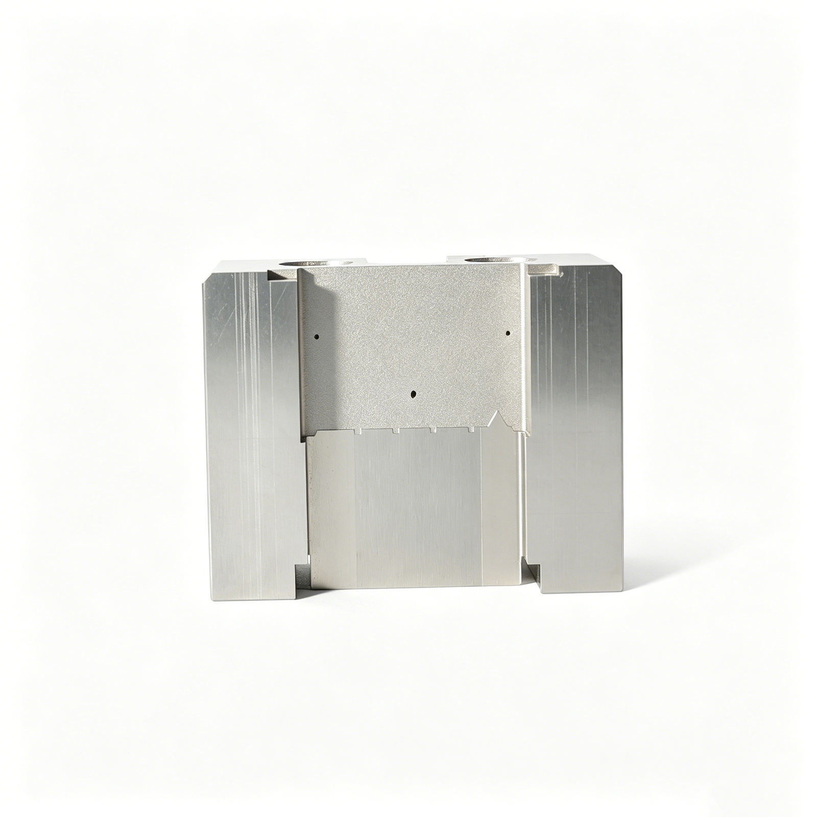
Retainer plates secure punches in precise arrays; backing plates distribute press force and prevent deflection. Multi-cavity micro-connector tooling demands ground flatness ≤ 0.005 mm across the plate to ensure uniform contact pressure.
Off-the-shelf plates work for single-punch layouts; any array with pitch ≤ 1.0 mm or tonnage > 50 kN requires custom machining, often with locating dowels positioned to +/-0.002 mm by slow-wire EDM.
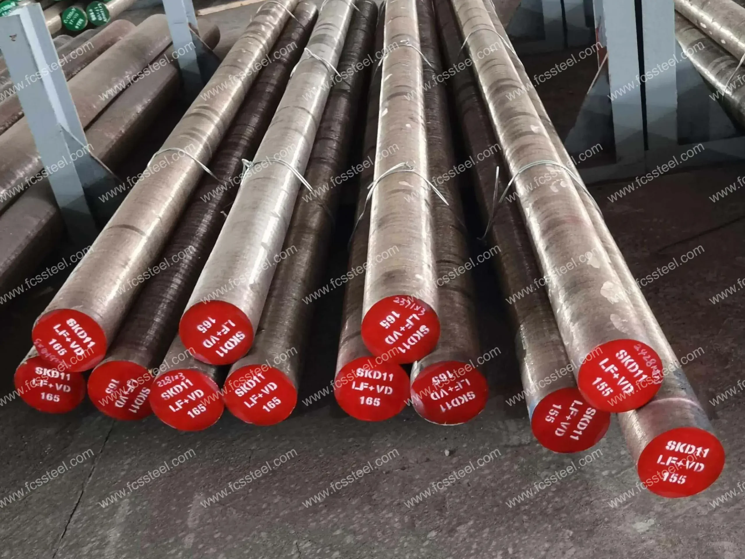
4. Materials for Punch Mold Components: Steel Grades and Carbide Options
Material selection directly determines service life, dimensional stability and total cost of ownership for punch mold components. Tool steels and tungsten carbide each occupy distinct performance and economic zones, with hardness spanning HRC 58–64 and wear resistance varying by two orders of magnitude.
| Material | Hardness (HRC) | Wear Resistance | Relative Cost | Typical Use Case |
|---|---|---|---|---|
| SKD11 (D2) | 58–62 | Good | 1.0× | General-purpose punches, moderate-volume stamping, complex geometries requiring toughness |
| SKH51 (M2) | 62–64 | Very Good | 1.4× | High-speed production, thin-wall features, elevated working temperatures |
| ASP23 (PM steel) | 62–64 | Excellent | 2.2× | Ultra-fine detail, micro-connector tooling, extended tool life in high-volume runs |
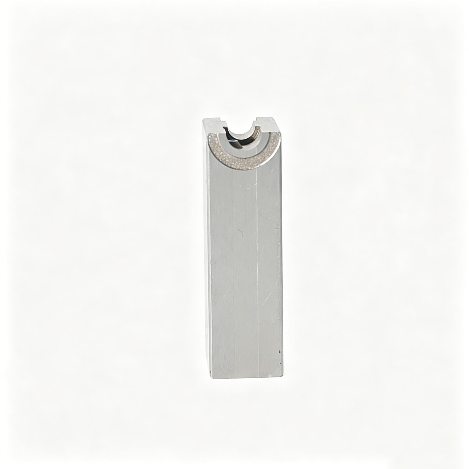
| Tungsten Carbide | 88–92 HRA | Outstanding | 3.5–4.0× | Million-cycle stamping, abrasive materials, sub-0.05 mm features where deflection is critical |
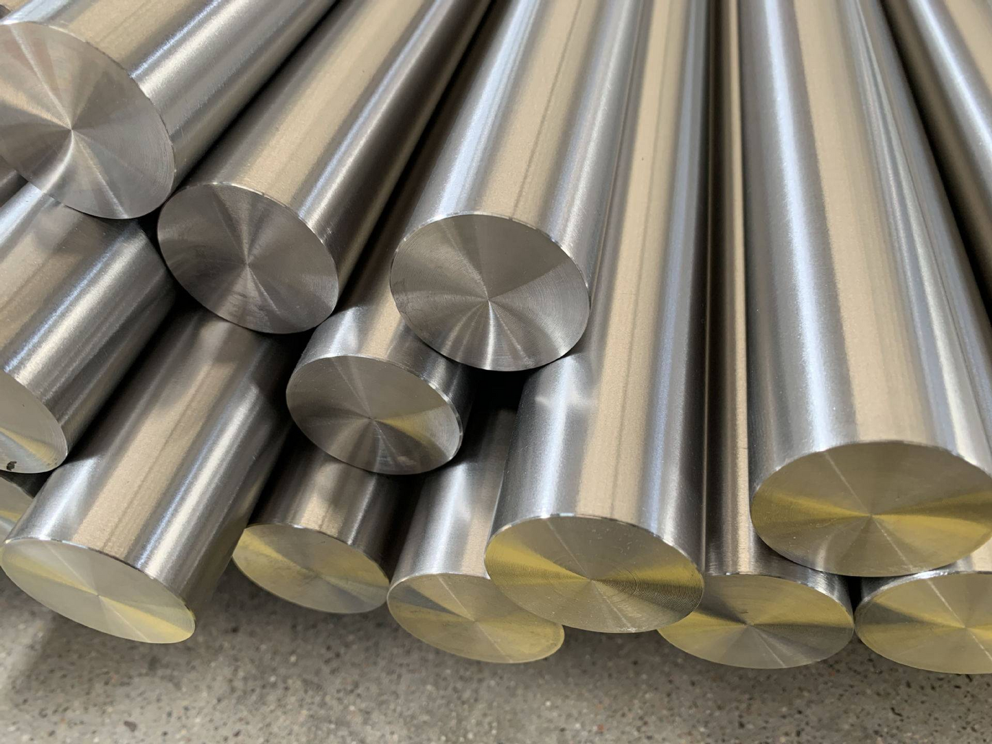
| 440C / 17-4PH | 54–58 | Moderate | 1.3× | Medical-device tooling, corrosive environments, pharmaceutical and food-contact applications |
5. Customization and Surface Treatment Options for Punch Mold Components
Customization and surface treatment extend punch mold component life, reduce cycle time and improve part release. XUXIANG integrates CNC machining to +/-0.001 mm, slow-wire EDM to +/-0.002 mm and mirror-grade polishing to Ra 0.1 µm to meet micro-connector and high-cavity tooling demands.
CNC and Wire-EDM for Micro-Features
Slow-wire EDM delivers corner radii down to R ≤ 0.015 mm and positioning repeatability of +/-0.002 mm, essential for high-density terminal punches and micro-pin tooling. Beijing Jingdiao high-precision CNC mills electrode geometries and complex core profiles that conventional machining cannot reach, enabling conformal cooling channels and undercut features in hardened steels.
Surface Coatings: TiN, TiCN and DLC
Coating selection directly impacts friction, wear resistance and maintenance intervals. TiN (titanium nitride) raises surface hardness by 2–3× at moderate cost; TiCN adds carbon for lower friction; DLC (diamond-like carbon) achieves the lowest coefficient (0.05–0.1) and extends punch life 5–10× in abrasive stamping, though at 3–4× the cost of TiN.
| Coating | Hardness Increase | Friction Coeff. | Cost Premium |
|---|---|---|---|
| TiN | 2–3× | 0.4–0.5 | 1.0× |
| TiCN | 3–4× | 0.2–0.3 | 1.5–2× |
| DLC | 4–6× | 0.05–0.1 | 3–4× |
Polishing and Laser Marking for Traceability
Mirror polishing to Ra 0.05–0.2 µm minimizes resin adhesion and accelerates ejection in micro-connector molds, cutting cycle time by 10–15%. Laser marking embeds serial numbers, material codes and revision levels without affecting dimensional integrity, enabling full traceability through ISO 9001:2015 FAI documentation and supporting warranty claims and design-change management.
6. Key Quality and Performance Criteria for Punch Mold Components
Punch mold components must meet five non-negotiable performance benchmarks to avoid costly downtime and rework. Dimensional tolerance, surface integrity, heat treatment, geometric accuracy and fatigue life together determine whether a part will survive 500,000 cycles or fail at 50,000.
Dimensional Tolerance and Verification
Precision punch mold components require +/-0.001 to +/-0.005 mm tolerance depending on application — micro-connector tooling demands the tightest bands. XUXIANG validates every part on a ZEISS MICURA CMM with 0.7 µm resolution, supplemented by Nikon toolmaker’s microscopes for edge radii and surface transitions.
Optical comparators cross-check profile geometry; deviations beyond +/-0.002 mm trigger rework. Poor tolerance manifests as misalignment, flash and premature wear, often costing 3–5× the original part price in emergency replacements.
Surface Finish and Integrity
Mirror-grade EDM finishes down to Ra 0.1 µm prevent galling and reduce ejection forces in high-cycle stamping. Surface roughness above Ra 0.4 µm accelerates adhesive wear and particle generation.
XUXIANG’s Sodick and Charmilles sinker EDM achieve Ra 0.1–0.2 µm on hardened tool steels. Inspection includes visual checks under 50× magnification and surface-integrity profilometry to detect micro-cracks or recast layers that seed fatigue failure.
Heat-Treatment Certification and Hardness
Heat-treated punches and dies must reach HRC 58–62 for carbide-grade steels; under-hardened parts lose geometry within 10,000 cycles. Every XUXIANG component ships with material certificates and hardness test reports traceable to batch furnace logs.
Rockwell and Vickers hardness testing at three zones per part ensures uniform through-hardening. Inadequate heat treatment causes rapid wear, burr formation and dimensional creep, often discovered only after first-article runs fail quality gates.
Concentricity, Perpendicularity and Geometric Accuracy
Guide pins and bushings require concentricity within 0.003 mm and perpendicularity within 0.005 mm to prevent binding and misalignment. XUXIANG’s slow-wire EDM holds +/-0.002 mm positional tolerance, verified by CMM datum checks.
Poor geometric accuracy causes alignment drift, uneven die wear and scrap spikes above 2%. Buyers should demand geometric dimensioning and tolerancing (GD&T) call-outs and full FAI documentation with datum references.
Fatigue Life and Cycle Testing
High-performance punch mold components must survive ≥500,000 cycles without measurable wear. Fatigue life depends on material grade, heat treatment, surface finish and stress concentration at radii.
XUXiang pre-qualifies tooling designs through DFM analysis by 10+ engineers, identifying stress risers before machining. Accelerated cycle testing and metallurgical cross-sections validate fatigue resistance; components failing before target life trigger root-cause analysis and process adjustments.
7. How to Choose a Punch Mold Components Manufacturer
Selecting a punch mold components supplier demands a methodical audit of capabilities, certifications and support infrastructure. The right partner combines precision machining, validated quality systems and transparent communication to eliminate tolerance drift and schedule risk.
Certifications and Quality Systems
ISO 9001:2015 is the baseline; IATF 16949 adds automotive-grade traceability for NEV and sensor applications. Request copies of active certificates and ask which ZEISS or Mitutoyo CMM models anchor the metrology lab — vague ‘quality inspection’ claims are a red flag.
XUXIANG operates under ISO 9001:2015 with ZEISS MICURA CMM verification to 0.7 µm, ensuring every batch includes dimensional FAI reports and material certificates.
Machining and In-House Capabilities
Verify wire-EDM resolution (+/-0.002 mm class on Sodick/Charmilles), 5-axis CNC for complex geometries and in-house heat treatment to control hardness uniformity. Outsourced coating or grinding adds lead time and traceability gaps.
Shops with Japanese EDM, German grinding and dedicated electrode CNC — like XUXIANG’s Sodick, Dawn and Beijing Jingdiao lineup — deliver tighter corner radii (R ≤ 0.015 mm) and mirror finishes (Ra 0.1 µm).
Lead Time, Support and Red Flags
Compare prototype cycles (7–10 days is competitive), regrinding policies and warranty terms. Avoid suppliers who cannot provide CMM reports, specify steel grades by AISI/DIN code or quote delivery windows longer than 3–4 weeks for standard geometries.
Geographic proximity matters less than IP protection: confirm NDA enforcement, secure file transfer and whether the facility segregates tooling data by customer.
8. Common Mistakes When Sourcing Punch Mold Components
Even micron-grade punch mold components fail when sourcing decisions ignore system-level engineering. Five recurring mistakes — tolerance isolation, material false economy, coating omission, CAD acceptance without validation and maintenance neglect — together account for over 60% of premature tooling replacement and unplanned downtime in high-volume stamping and connector production.
Specifying Tolerance Without Stack-Up Analysis
Buyers often call out +/-0.005 mm on a punch without modeling the cumulative effect of die plate, stripper and guide-post tolerances. A four-part assembly with +/-0.005 mm per component can yield +/-0.020 mm total deviation, causing misalignment and burr formation.
XUXIANG’s DFM team reviews mating-part drawings and calculates stack-up before machining, tightening critical interfaces to +/-0.002 mm where necessary to keep assembly variation below +/-0.008 mm and preserve part-to-part repeatability over million-cycle runs.
Choosing Lowest-Cost Material That Fails Early
Selecting unbranded tool steel or substituting SKD11 for high-speed applications saves 15–20% upfront but typically results in edge chipping by 50,000 cycles and complete failure before 200,000 strokes, versus 500,000+ for properly heat-treated SKH-51 or carbide grades.
Total cost of ownership including rework, line stoppages and expedited replacement orders can exceed 300% of the initial material premium, making carbide or premium alloy steel the economical choice for any production run above 100,000 pieces.
Ignoring Coating and Surface Treatment Options
Uncoated punches in stainless-steel or high-carbon materials experience galling and adhesive wear within 10,000–30,000 cycles. TiN, TiAlN or DLC coatings add 8–12% to unit cost but extend service life by 3–5× and reduce friction coefficients from ~0.4 to ~0.15, cutting press tonnage and heat generation.
XUXIANG applies mirror EDM finishes to Ra 0.1 µm before coating, ensuring adhesion and eliminating micro-pits that trap contaminants and accelerate localized corrosion in humid or chemically active stamping environments.
Accepting Generic CAD Without Validation
Procuring from suppliers who machine directly from customer CAD without engineering review leads to interference fits, insufficient draft angles and unmachinable corner radii. Rework cycles add 2–3 weeks and 25–40% cost.
Every XUXIANG project receives DFM feedback from 10+ engineers, flagging issues such as <R0.015 mm radii incompatible with wire-EDM electrode geometry, and recommending split-line adjustments that preserve function while enabling one-pass machining and ZEISS CMM verification to +/-0.001 mm.
Neglecting Maintenance and Regrinding Schedules
Buyers who lack documented inspection intervals run punches until catastrophic failure, scrapping both the component and in-process workpieces. Planned regrinding every 100,000–150,000 strokes costs ~20% of new-part price and recovers original geometry within +/-0.003 mm.
XUXIANG provides maintenance logs with each shipment, specifying visual-inspection checkpoints, recommended regrind cycles and return-to-factory reconditioning services that restore mirror finishes and coatings, extending total tool life beyond 1 million cycles at one-third replacement cost.
9. Pricing and Cost Structure for Punch Mold Components
Punch mold component pricing is driven by five variables: material grade (SKD11, ASP23, carbide), machining complexity (number of CNC operations, EDM hours, wire-EDM passes), surface treatment (nitriding, DLC, PVD), inspection depth (basic dimensional check versus full ZEISS CMM validation), and order quantity. A single prototype punch in SKD11 with +/-0.005 mm tolerance typically costs 3–5× the per-unit price of a 100-piece production run at +/-0.002 mm, because setup, programming and first-article inspection are amortized over fewer parts.
Volume discounts become significant above 50 pieces; at 100+ units, tooling amortization and batch EDM reduce per-part cost by 40–60 percent. For orders exceeding 500 pieces or multi-cavity projects, negotiate upfront tooling fees separately from per-component pricing to gain visibility into true unit economics and lock predictable costs across repeat buys.
| Quantity Tier | Unit Price Range (USD) | Lead Time (days) | Setup Cost (USD) |
|---|---|---|---|
| 1 pc (prototype) | $120–$280 | 5–7 | $150–$300 |
| 10 pcs (pilot) | $65–$150 | 7–10 | $200–$400 |
| 50 pcs (pre-production) | $35–$85 | 10–14 | $250–$500 |
| 100+ pcs (production) | $18–$50 | 12–18 | $300–$600 |
10. Steps to Launch Your Precision Tooling Project with Punch Mold Components
Launching a precision tooling project with punch mold components requires a structured workflow that balances engineering rigor with delivery speed. XUXIANG’s 10+ engineering experts provide DFM feedback within 24 hours of CAD submission, compressing the validate-refine-produce cycle by roughly 30% versus industry norms.
Define Part Geometry and Tolerance Requirements
Start by documenting critical dimensions, corner radii, draft angles and positional tolerances in a 2D/3D CAD model (STEP, IGES or native SolidWorks). Specify whether you need +/-0.002 mm slow-wire precision, mirror-grade Ra 0.1 µm EDM finishes or standard CNC tolerances.
Include material call-outs (SKD11, tungsten carbide, ASP23) and any coating or heat-treatment preferences. Clear up-front specs reduce revision cycles and accelerate DFM turnaround.
Request CAD Validation and DFM Feedback
Submit your design for manufacturability review. XUXIANG’s engineering team flags undercuts, thin walls below 0.3 mm, sharp corners that risk electrode breakage and cooling-channel conflicts — all before tooling begins.
DFM feedback typically arrives within 24 hours and includes recommended adjustments for machinability, cost and tool life. Accept or iterate on these suggestions to lock the final geometry.
Review First-Article Inspection and Prototype Trials
Before committing to volume, request a first-article inspection (FAI) report with ZEISS CMM data, material certificates and surface-roughness readings. XUXIANG’s five-step QC flow — spectral analysis, in-process monitoring, CMM verification, surface checks and FAI documentation — ensures every dimension matches your drawing.
Run prototype trials in your production press to validate fit, cycle time and part quality. Iterative refinement at this stage prevents costly rework later.
Establish Regrinding SLA and Scale to Production
Agree on a regrinding and maintenance service-level agreement: acceptable wear limits, turnaround time and cost per cycle. Precision punch mold components typically support 50,000–500,000 cycles between regrinds, depending on material and application.
Once validated, release the production order. XUXIANG’s 2025 Quanzhou expansion adds 1,400 m² and a targeted 200% output lift, enabling dependable mass production with lead times roughly 30% faster than industry average.
Start Your Precision Punch Mold Components Project Today
Upload your CAD file or technical drawing and receive a detailed quote within 24 hours — backed by +/-0.001 mm machining precision and ISO 9001:2015 quality.