
PCS Mold Components — Micron-Stable Precision Tooling for 5G, Automotive & Medical
XUXIANG manufactures high-precision PCS mold components held to +/-0.001 mm, with mirror-grade EDM finishes, ZEISS CMM validation, and quotes returned in 24 hours.
Featured PCS Mold Components
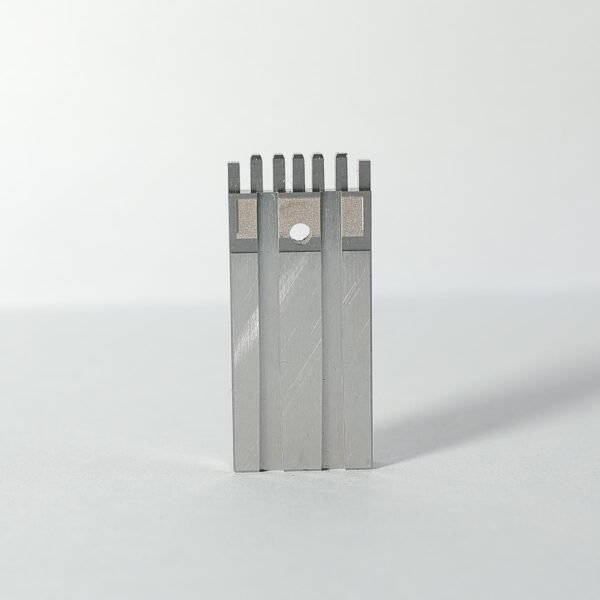
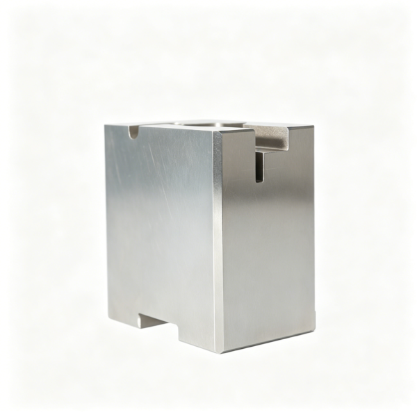
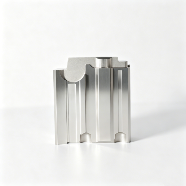
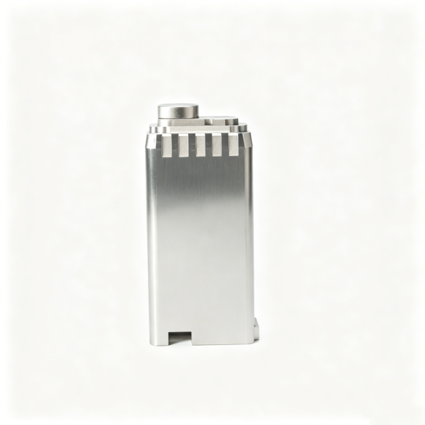
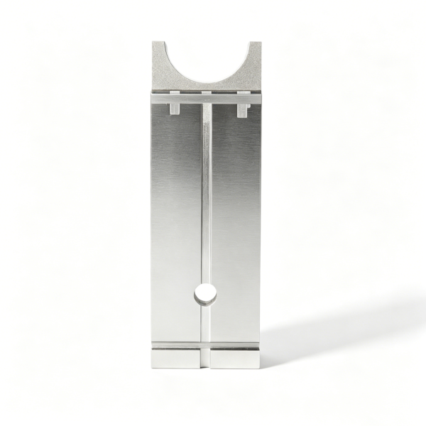
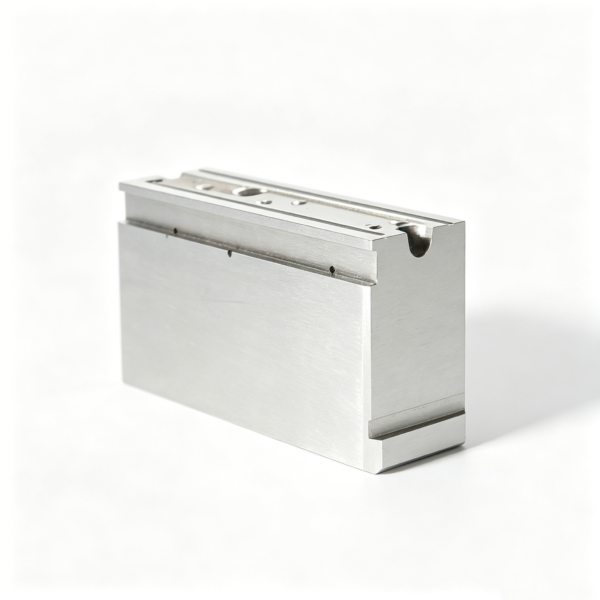
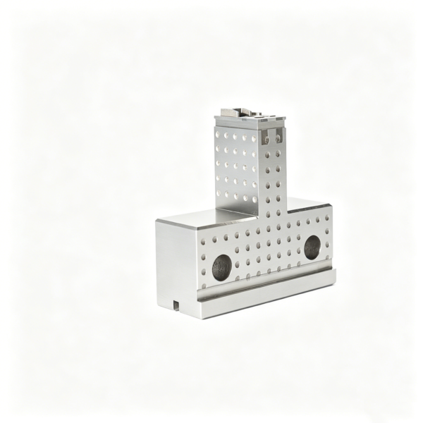
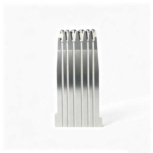
Precision Mold Components in Action


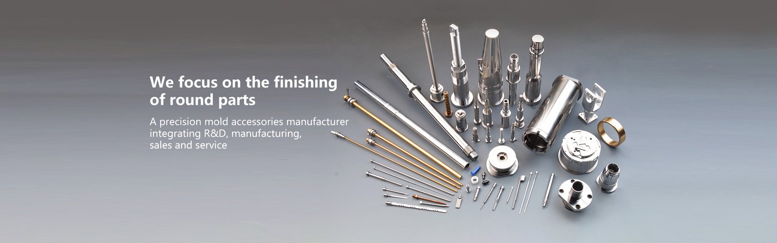
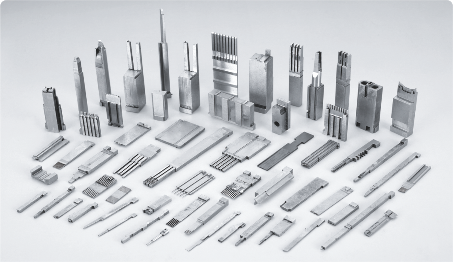
Why XUXIANG Precision Tooling Stands Out
+/-0.001 mm Machining Precision
Micron-stable accuracy on every PCS mold component, verified by ZEISS MICURA CMM with 0.7um resolution and Nikon toolmaker’s microscopes for dimensional integrity.
Mirror-Grade EDM Surface Finish
Ra 0.1um finishes from Sodick slow-wire and Mitsubishi mirror EDM systems eliminate secondary polishing and ensure optical-class mating surfaces on precision tooling.
24-Hour Quote, 3–7 Day Samples
Engineering-backed quotations returned within one business day, with prototype components shipped in 3 to 7 days for rapid design validation.
Dual-Factory Capacity Since 2025
Dongguan R&D hub plus Quanzhou volume plant deliver 200% expanded capacity, balancing precision micro-machining with dependable mass production at scale.
Full DFM from 10+ Experts
Design-for-manufacturing feedback before production prevents tolerance failures, material mismatches and costly rework, backed by ISO 9001:2015 process control and FAI documentation.
Complete FAI & Material Certificates
Every shipment includes first-article inspection reports, CMM measurement data and material spectral analysis certificates for full traceability and compliance assurance.
Mold Components Machined to +/-0.001 mm
Full catalog of precision mold spare parts and inserts for electronics, automotive, 5G and medical-device tooling — EDM-finished, CMM-verified and shipped with FAI documentation.
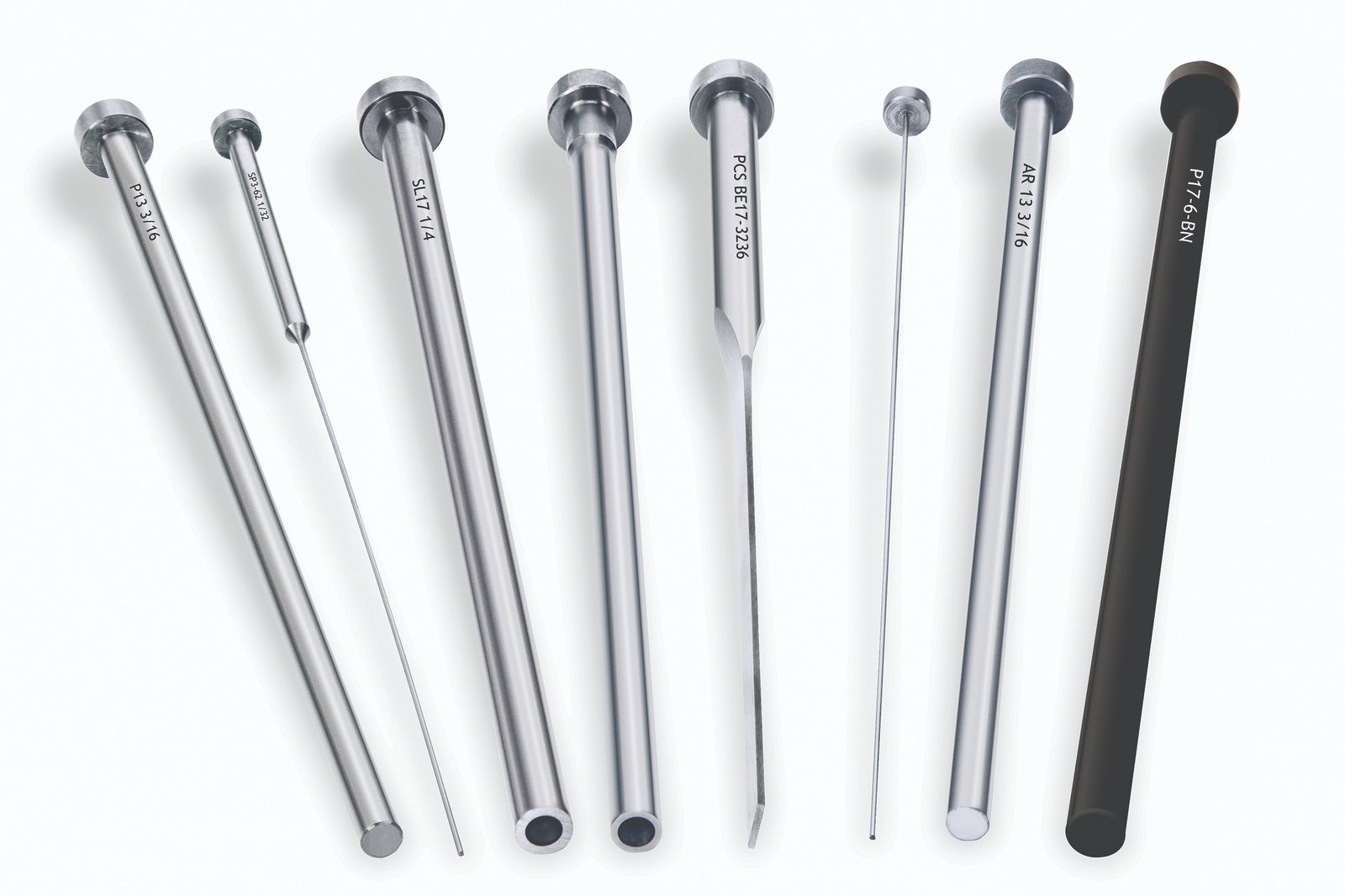
Ejector Pins
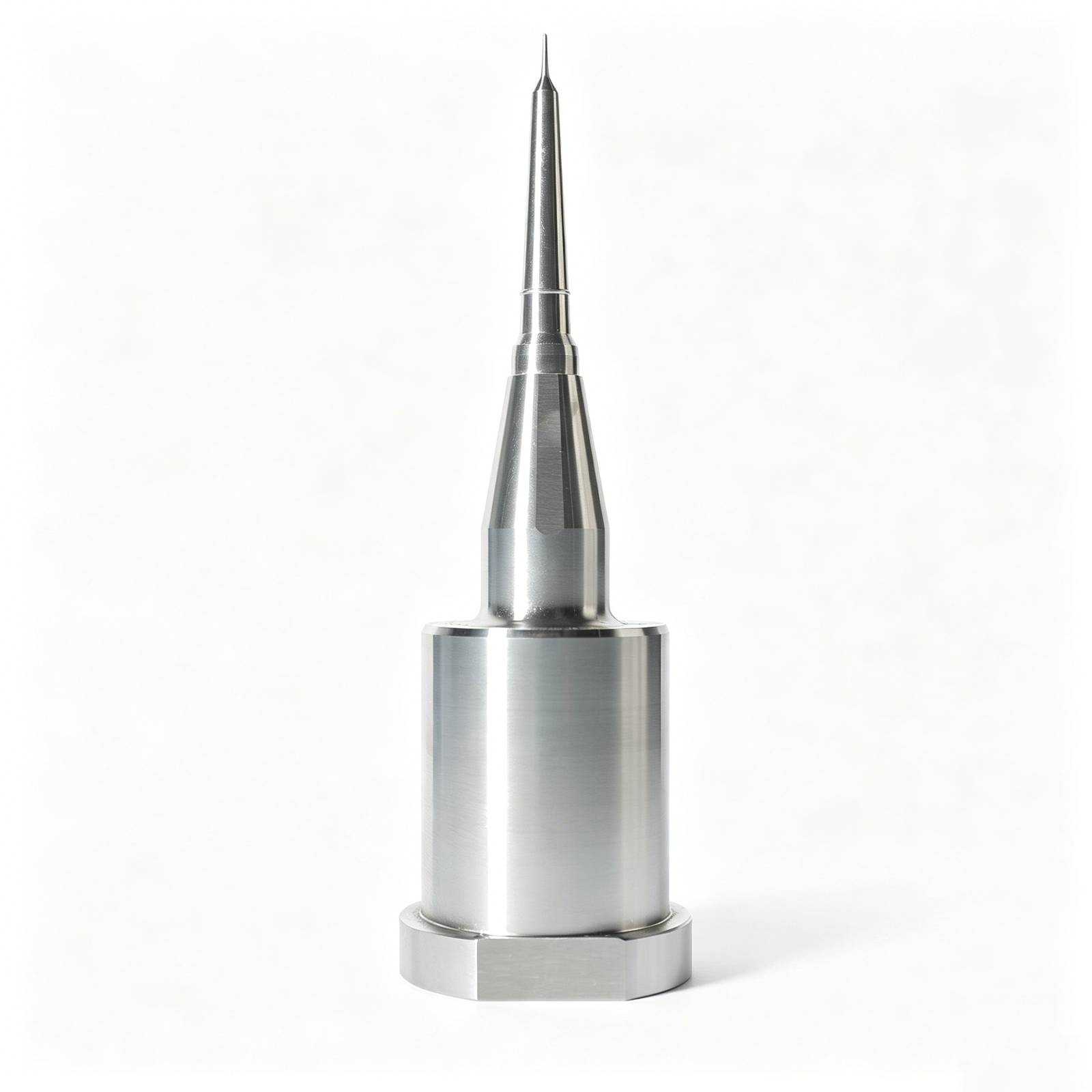
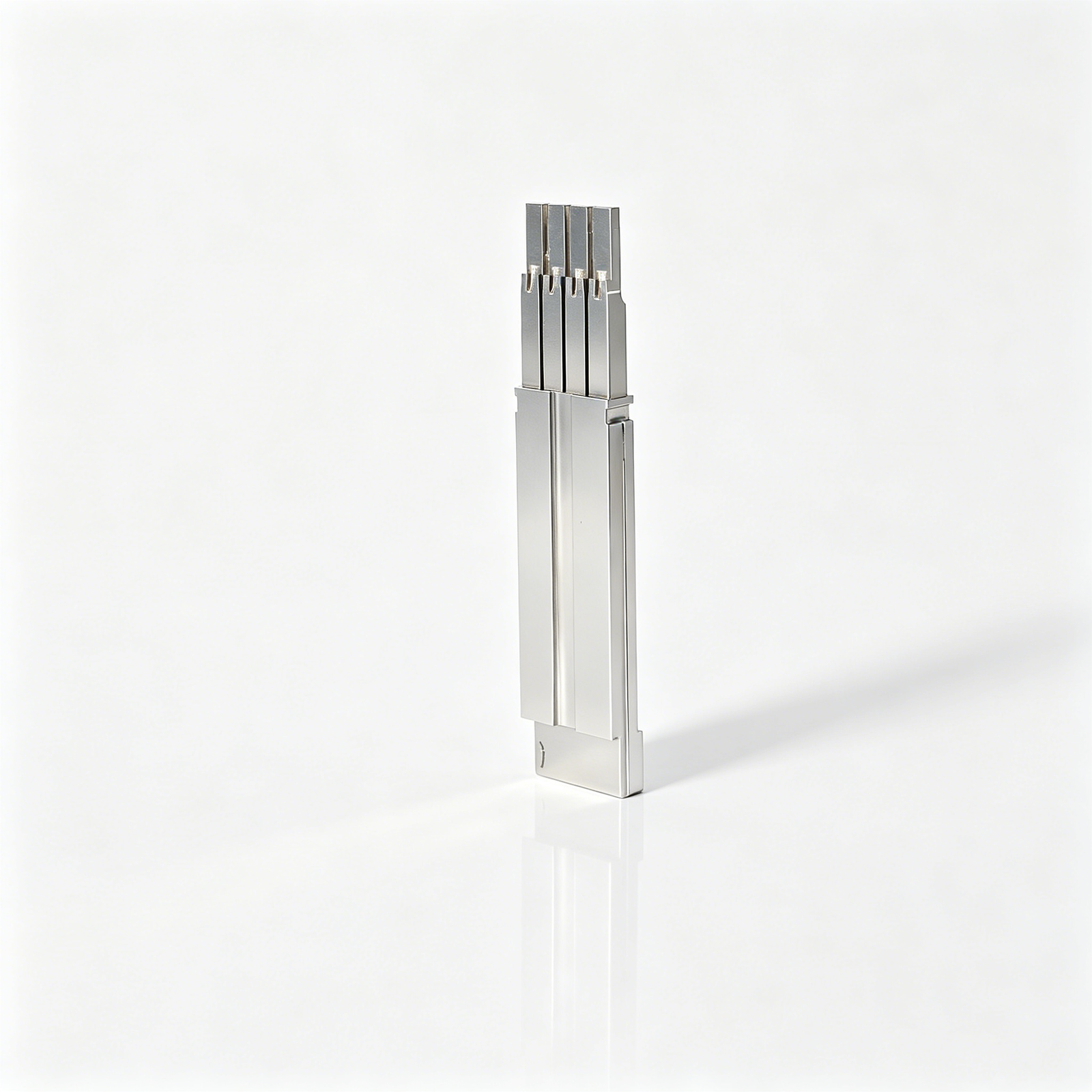
Ejector pins ground and wire-EDM’d to +/-0.002 mm positional tolerance, with surface finishes down to Ra 0.1 µm for high-cycle ejection in thin-wall electronics and micro-connector molds. Available in SKH-51, tungsten carbide and custom alloys, validated on ZEISS MICURA CMM and supplied with material certificates.
Get a Quote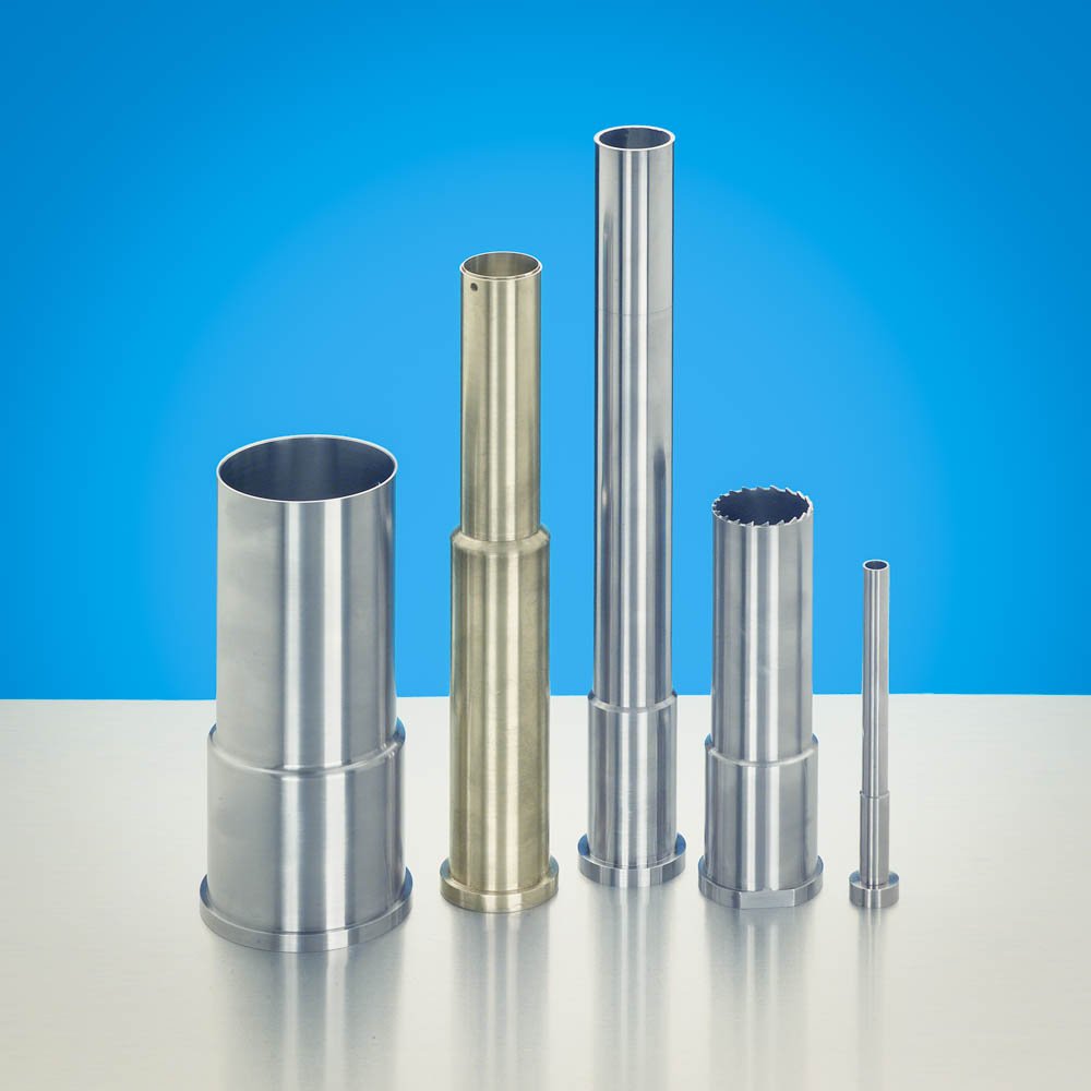
Ejector Sleeves
Ejector sleeves machined on Fanuc CNC and finish-ground to hold +/-0.001 mm on inner and outer diameters, ensuring concentric ejection in deep-draw and multi-cavity automotive tooling. Supplied with dimensional FAI reports and compatible with standard DIN, HASCO and DME mold-base systems.
Get a Quote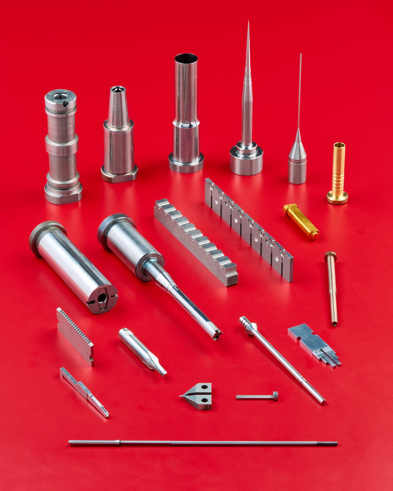
Core Pins
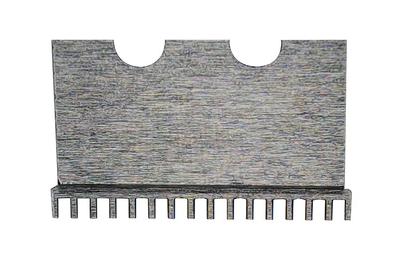
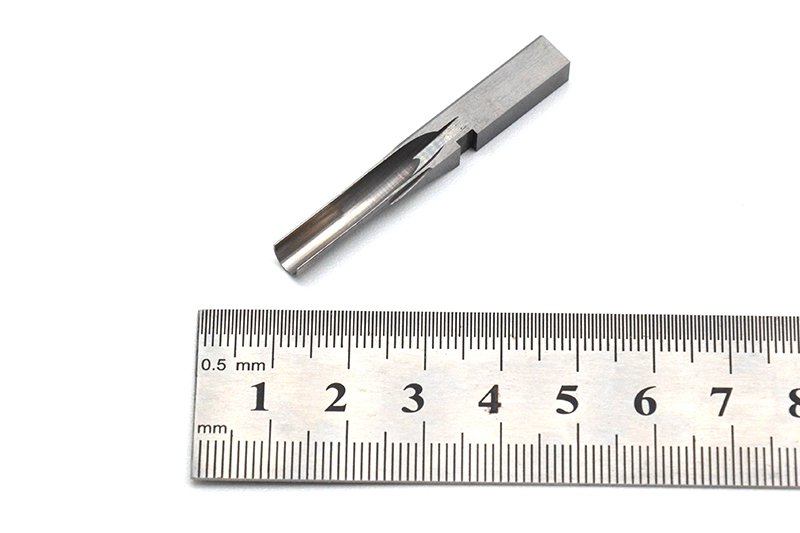
Core pins for micro-feature molding — slow-wire EDM on Sodick and Seibu equipment, capable of corner radii down to R 0.015 mm and straightness within 0.003 mm over length. Used in 5G RF connectors, board-to-board terminal tooling and high-density pin arrays, with Nikon toolmaker’s microscope verification at final inspection.
Get a Quote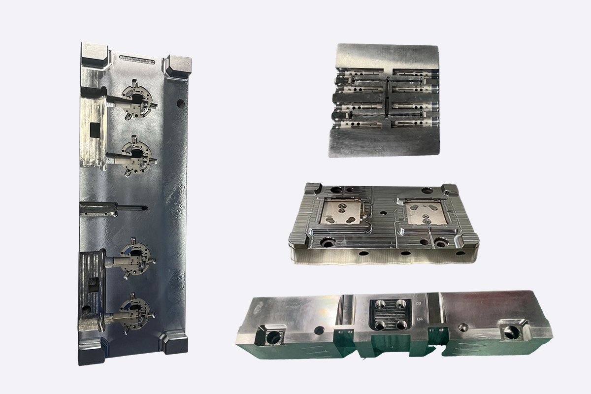
Cavity & Core Inserts (Mold Inserts)
Cavity and core inserts combining CNC roughing, precision EDM and mirror polishing to Ra 0.1 µm. Multi-cavity layouts, conformal cooling channels and insert-molded metal-stamping integration supported. DFM review by 10+ mold engineers before machining; ideal for consumer electronics housings, automotive sensor enclosures and medical-device cases.
Get a Quote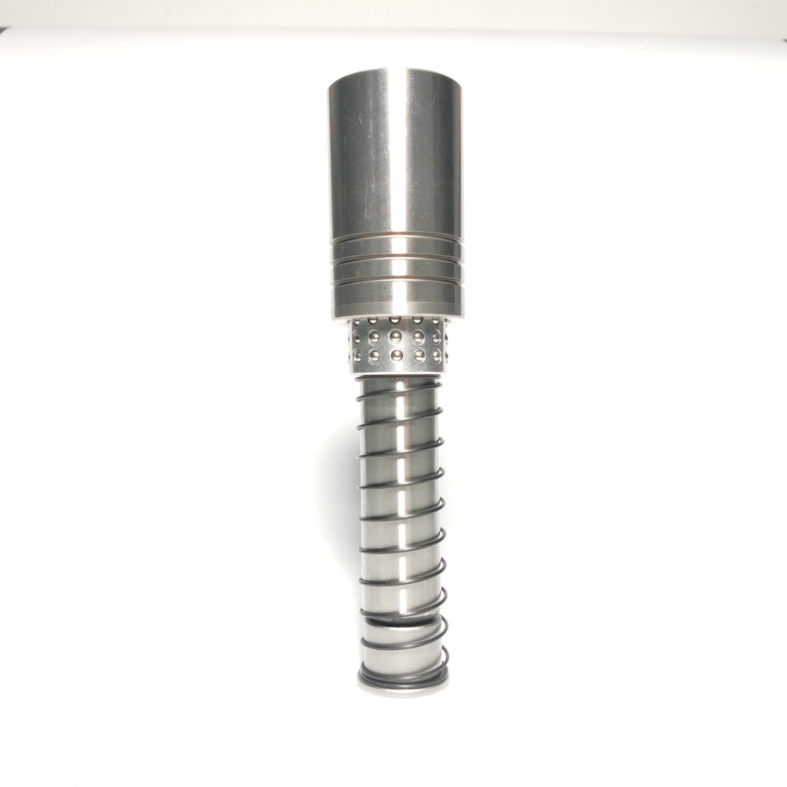
Guide Pins / Leader Pins
Guide pins manufactured from case-hardened alloy steel, centerless-ground to +/-0.001 mm diameter tolerance and heat-treated to HRC 58–62. Ensures repeatable mold alignment across 1 million+ cycles in high-volume production for automotive interiors, industrial connectors and LED structural tooling.
Get a Quote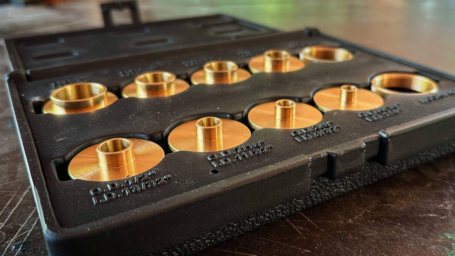
Guide Bushings
Guide bushings precision-bored and reamed to +/-0.002 mm, with internal surface finish better than Ra 0.4 µm to minimize wear and maintain alignment accuracy. Compatible with HASCO, DME and LKM standards; supplied with hardness certificates and dimensional inspection reports from ZEISS CMM.
Get a Quote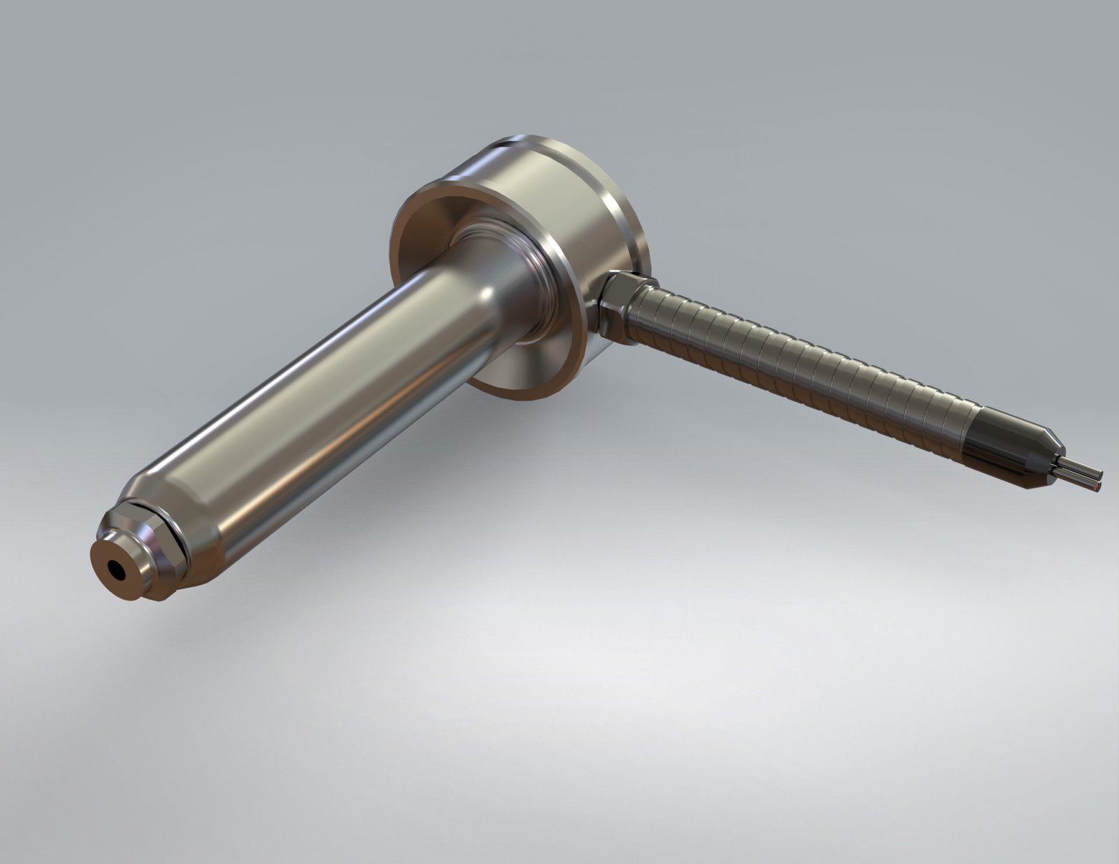
Sprue Bushings
Sprue bushings CNC-turned and polished, with spherical radius ground to +/-0.005 mm and nozzle seat finished to Ra 0.2 µm for leak-free hot-runner interface. Standard and custom geometries available; material options include H13, SKD61 and stainless steel, all supplied with spectral analysis and heat-treatment records.
Get a Quote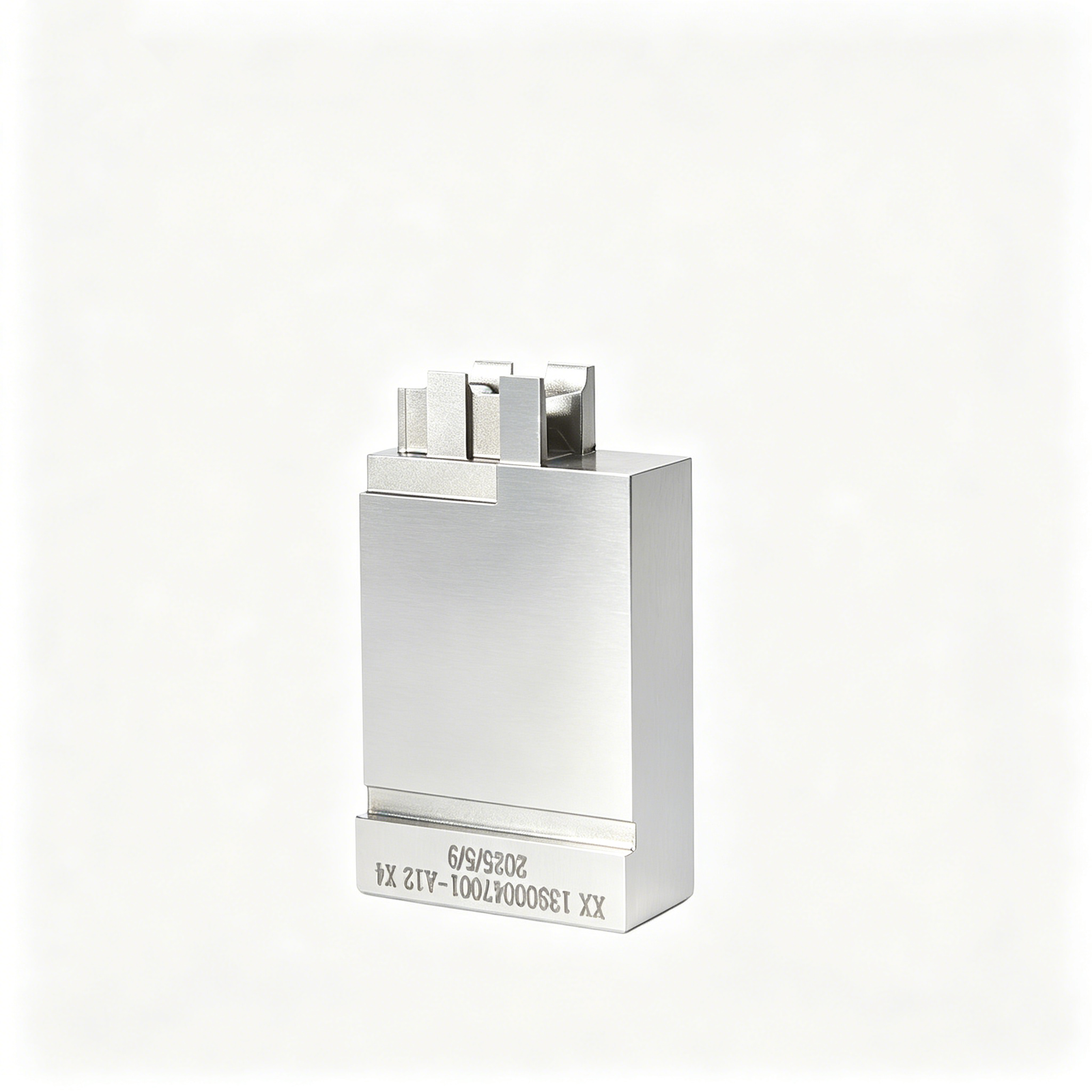
Locating Rings
Locating rings machined to HASCO and DME dimensional standards, with centering diameter held to +/-0.01 mm and flatness within 0.005 mm. Ensures precise nozzle-to-sprue alignment in high-temperature injection molding; suitable for automotive, telecom and medical-device mold bases.
Get a Quote
Sliders & Slides
Sliders and slides for complex side-action tooling, combining wire EDM, CNC milling and precision grinding to achieve +/-0.003 mm positional accuracy and Ra 0.2 µm on wear surfaces. Designed for undercut features in automotive lamp housings, consumer-electronics enclosures and industrial-connector shells.
Get a Quote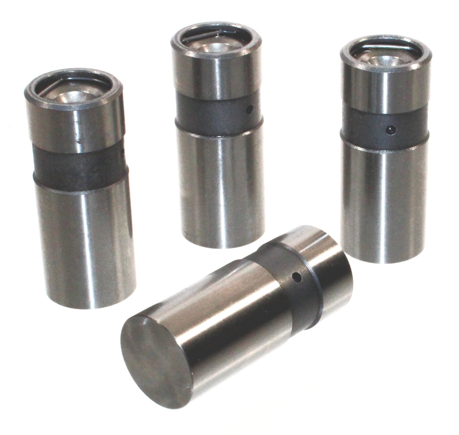
Lifters & Angle Lifters
Lifters and angle lifters engineered for reliable core pull in deep-draft and multi-angle geometries. Machined on Fanuc CNC with EDM-finished cam surfaces, holding angle tolerance within +/-0.05° and surface finish to Ra 0.3 µm. Used in automotive interior trim, NEV battery-connector housings and medical-device snap-fit assemblies.
Get a Quote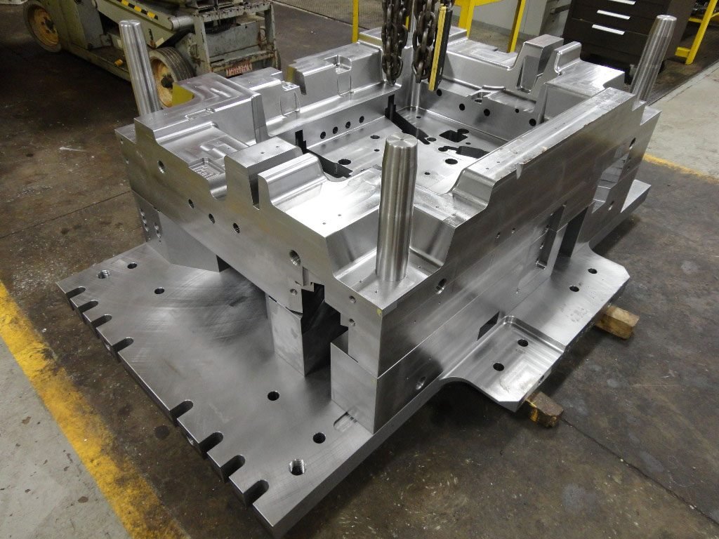
Mold Bases
Custom mold bases fabricated to customer CAD specifications or adapted from HASCO, DME and LKM standards. CNC-milled from pre-hardened P20, NAK80 or tool steel, with flatness and parallelism within 0.01 mm. Includes precision-bored guide and ejector-pin holes, ready for insert installation and final assembly.
Get a Quote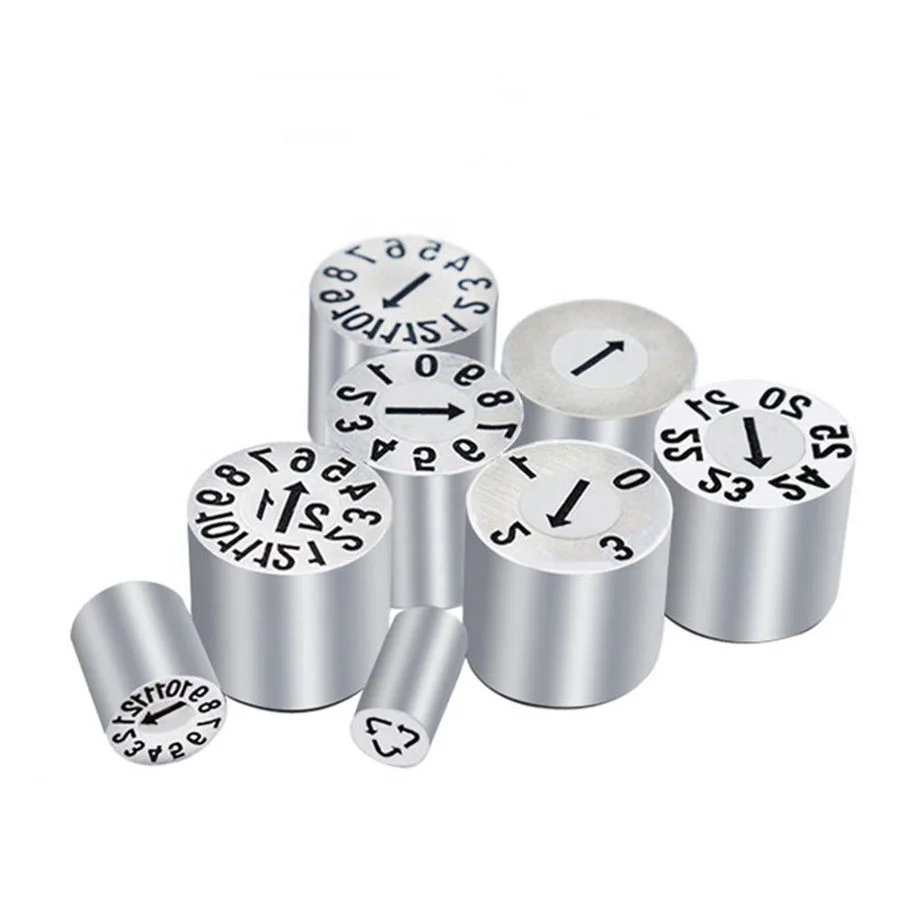
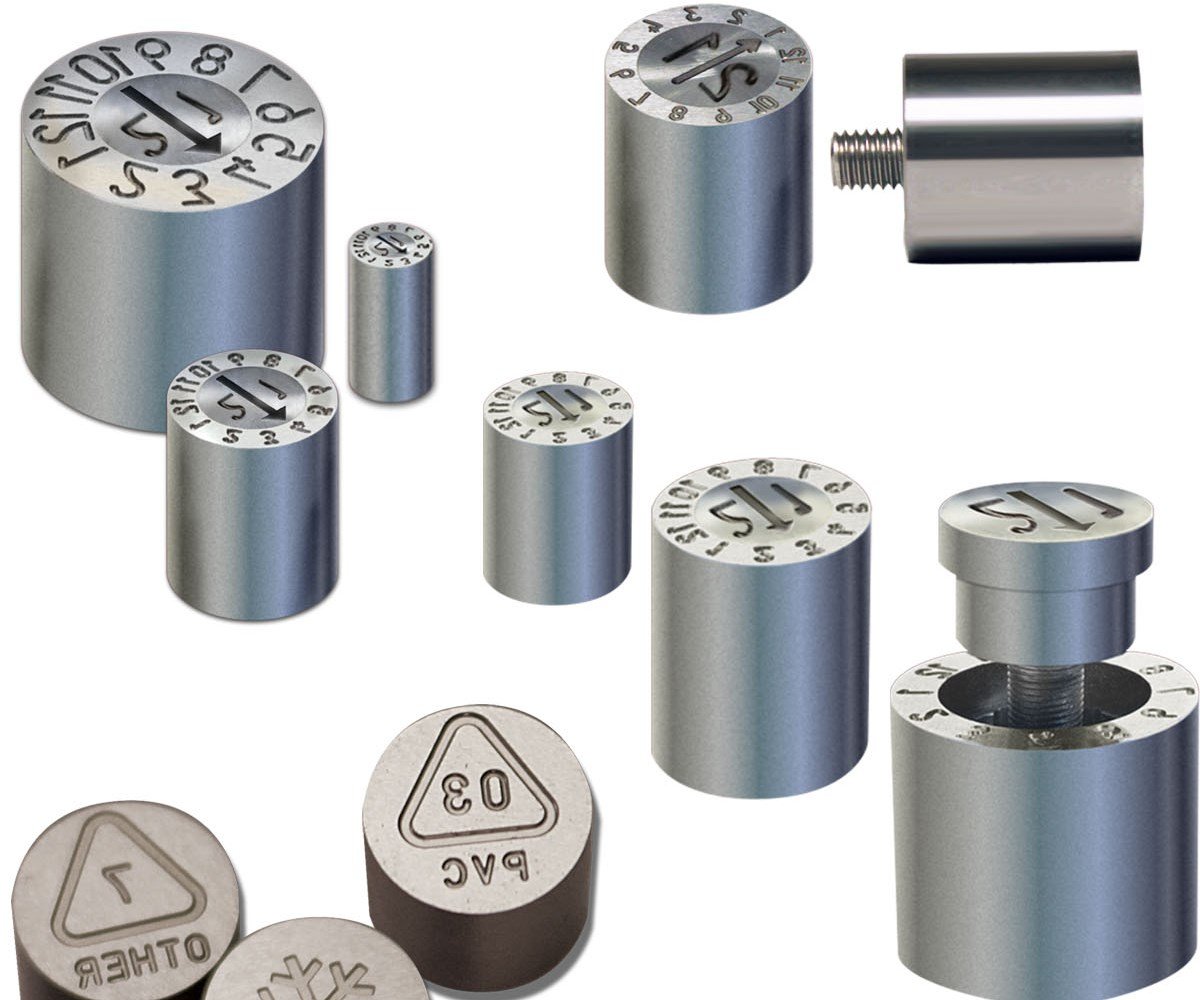
Date Stamps & Mold Accessories
Date stamps and mold accessories including engraved date inserts, venting pins, parting-line locks and ejector-return pins. Wire-EDM engraving down to 0.3 mm character height, with positional accuracy +/-0.01 mm. All accessories supplied with dimensional inspection data and compatible with standard mold-base systems.
Get a Quote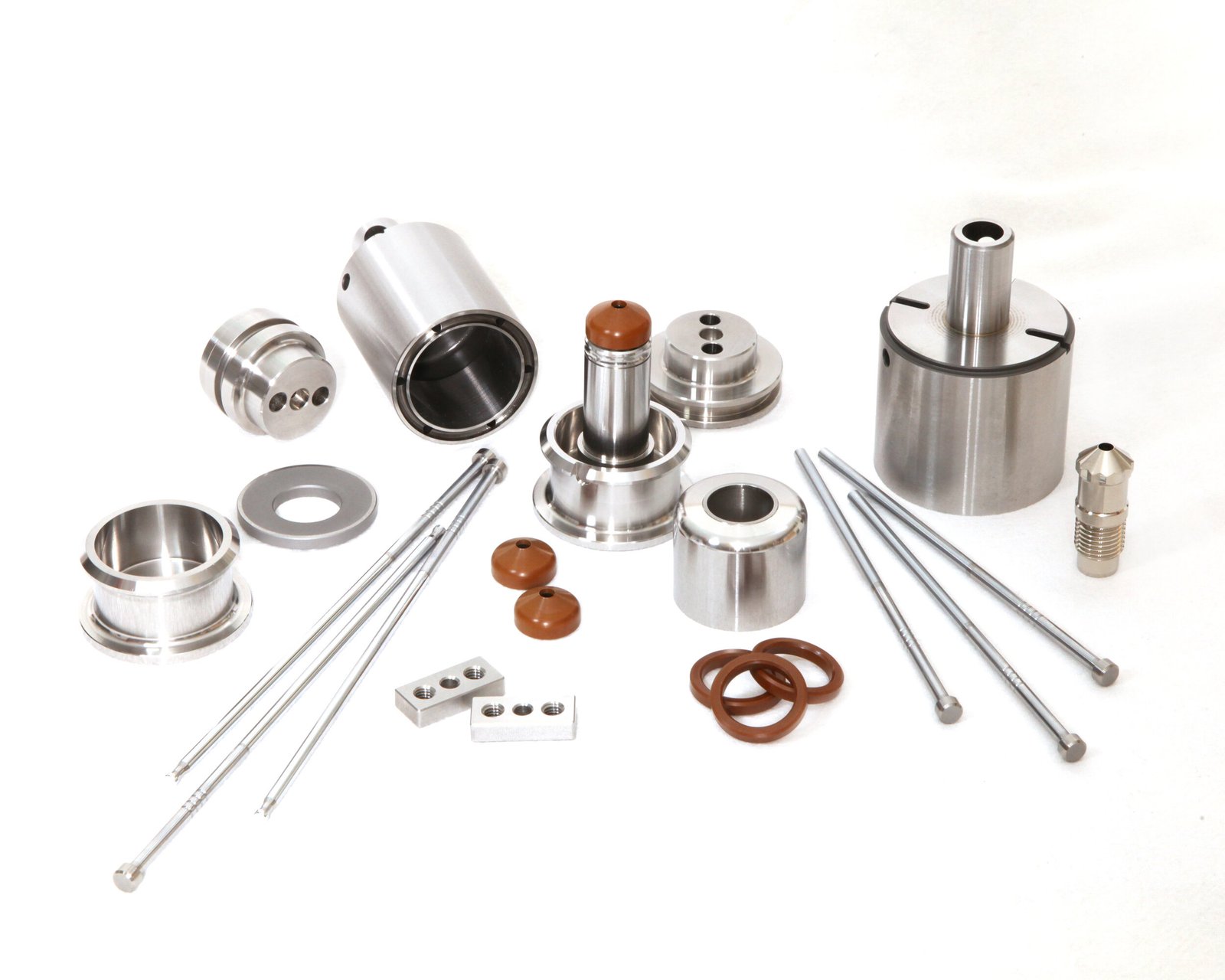
Hot Runner Components
Hot runner mold components including nozzle tips, manifold blocks, heating-element bores and thermal-barrier plates. CNC-machined and EDM-finished to +/-0.005 mm, with internal flow channels polished to Ra 0.4 µm. Designed for balanced fill in multi-cavity automotive, telecom and consumer-electronics applications.
Get a Quote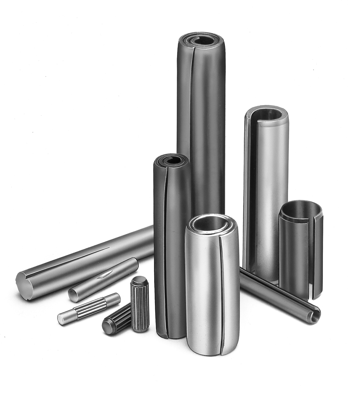
Mold Springs & Dowel Pins
Mold springs supplied in compression, extension and nitrogen-gas configurations, paired with precision-ground dowel pins held to h6 tolerance. Springs tested for load consistency within +/-5%; dowel pins case-hardened to HRC 58–62 and inspected for diameter, straightness and surface finish on ZEISS CMM.
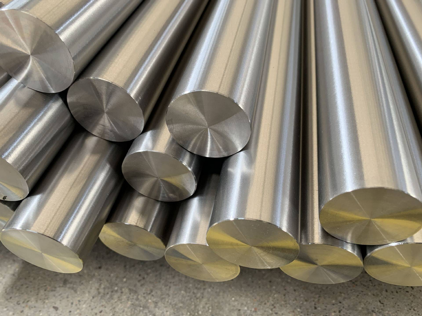
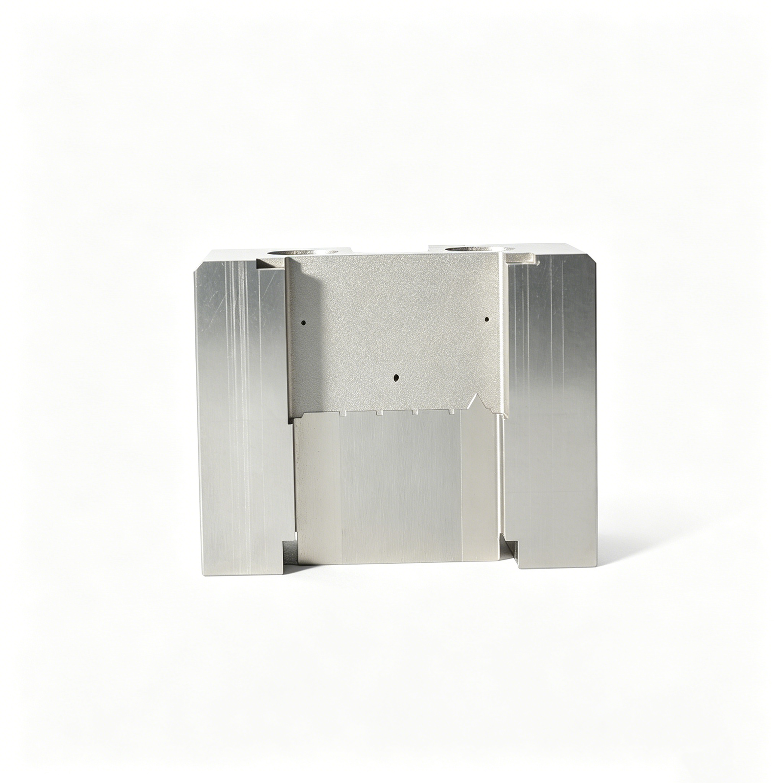
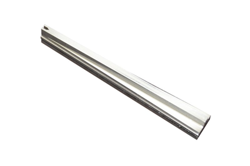
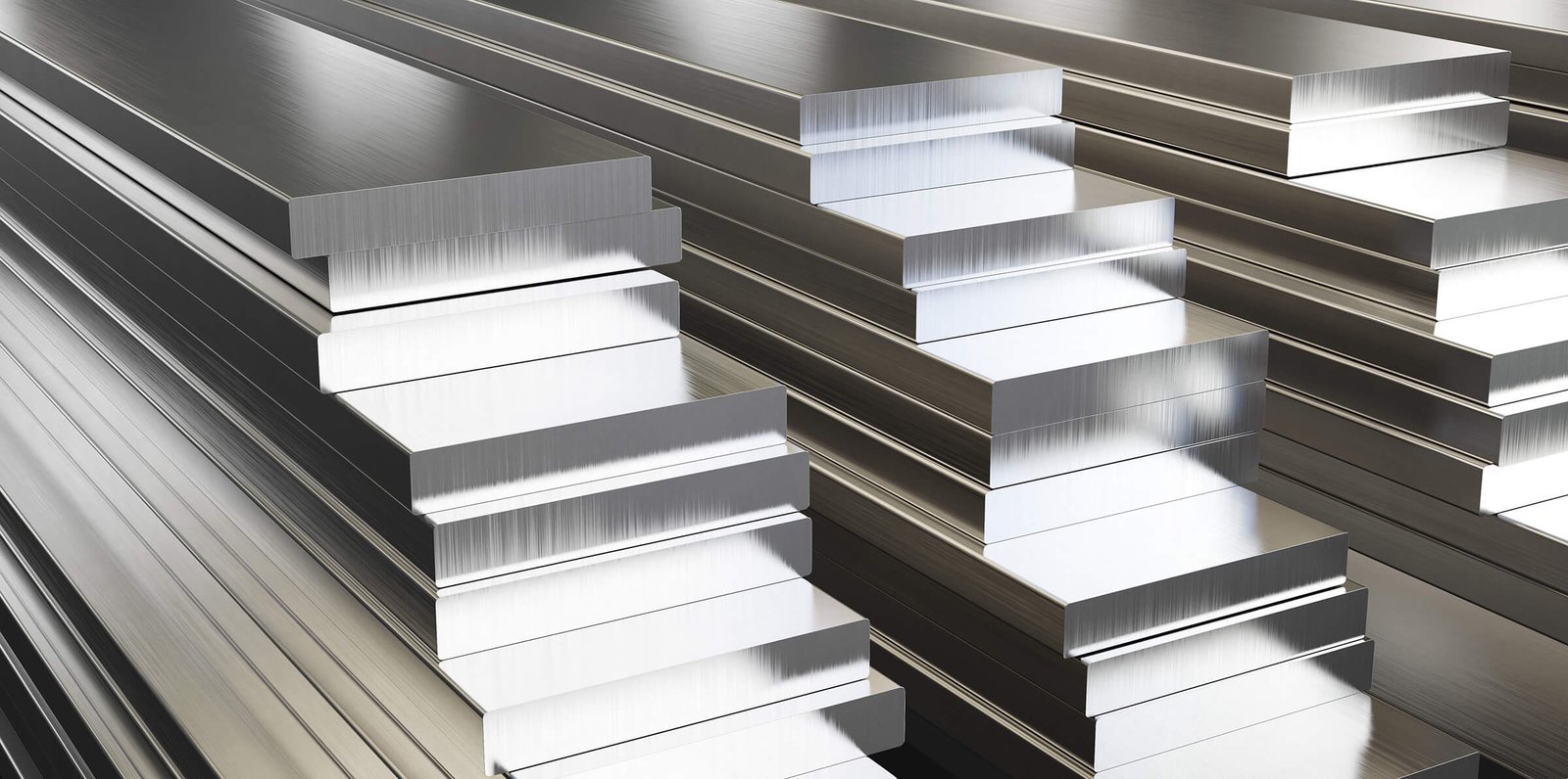
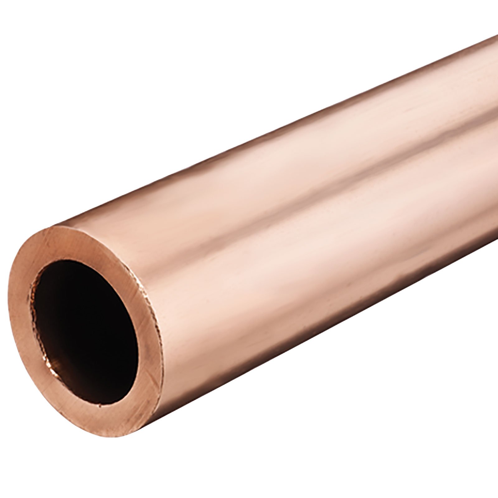
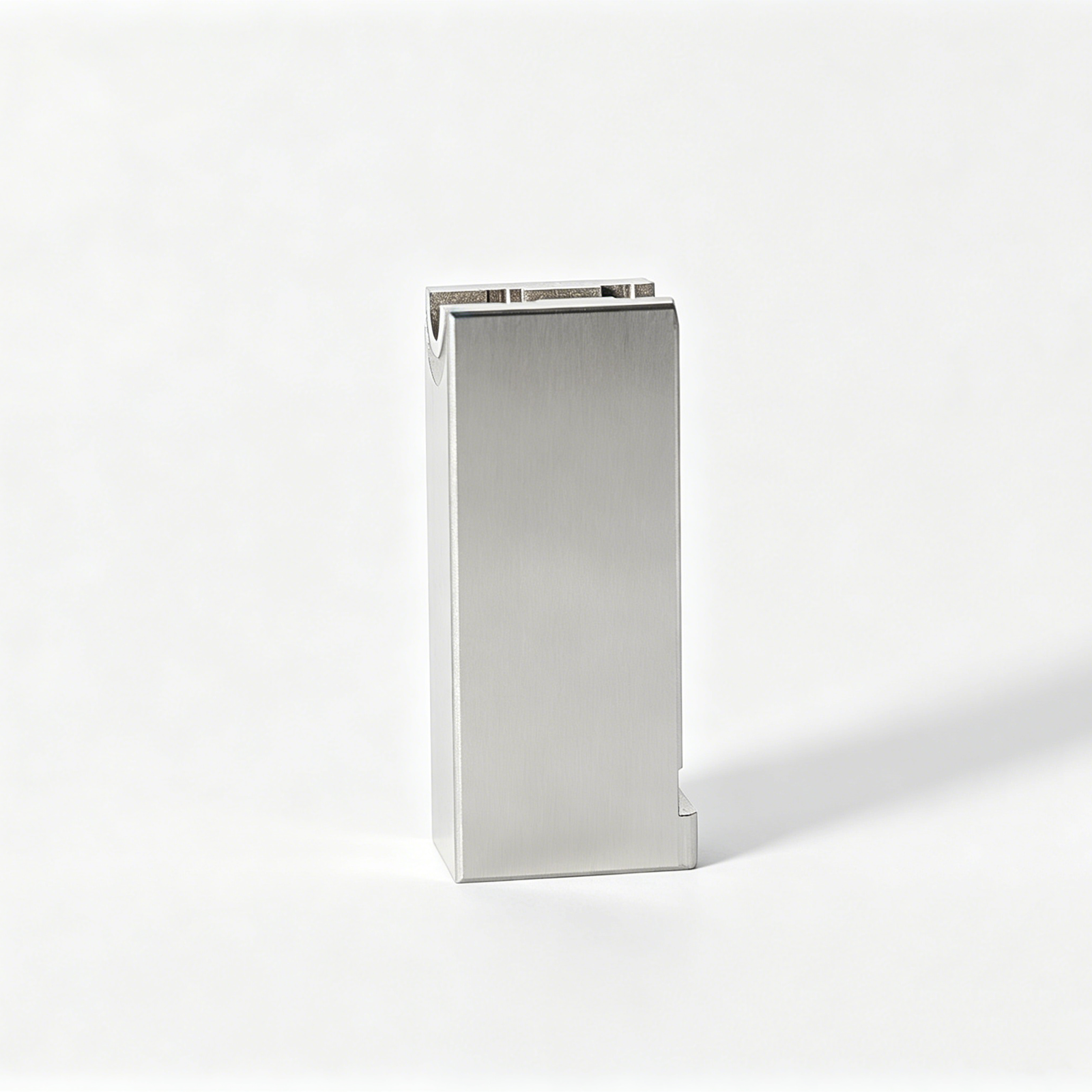
Get a QuoteMaterials We Machine to +/-0.001 mm Tolerance
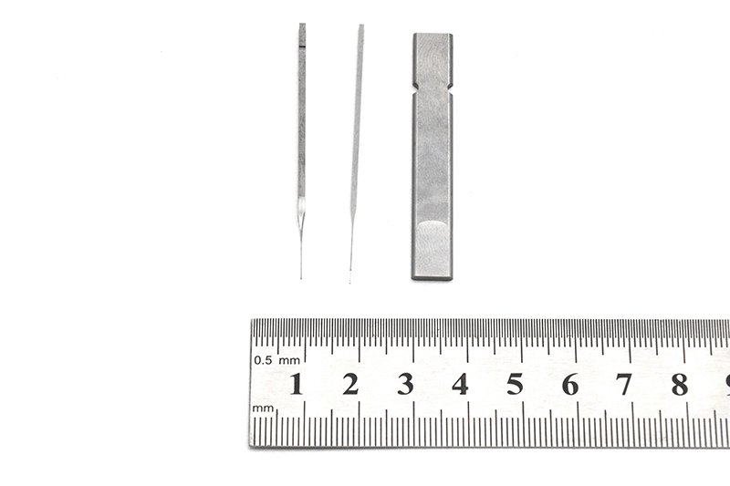
Precision Processes Behind Every Component
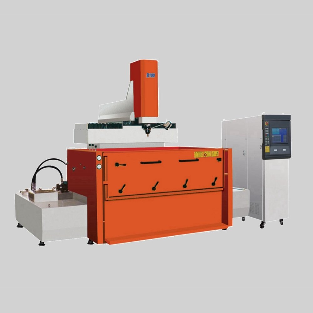
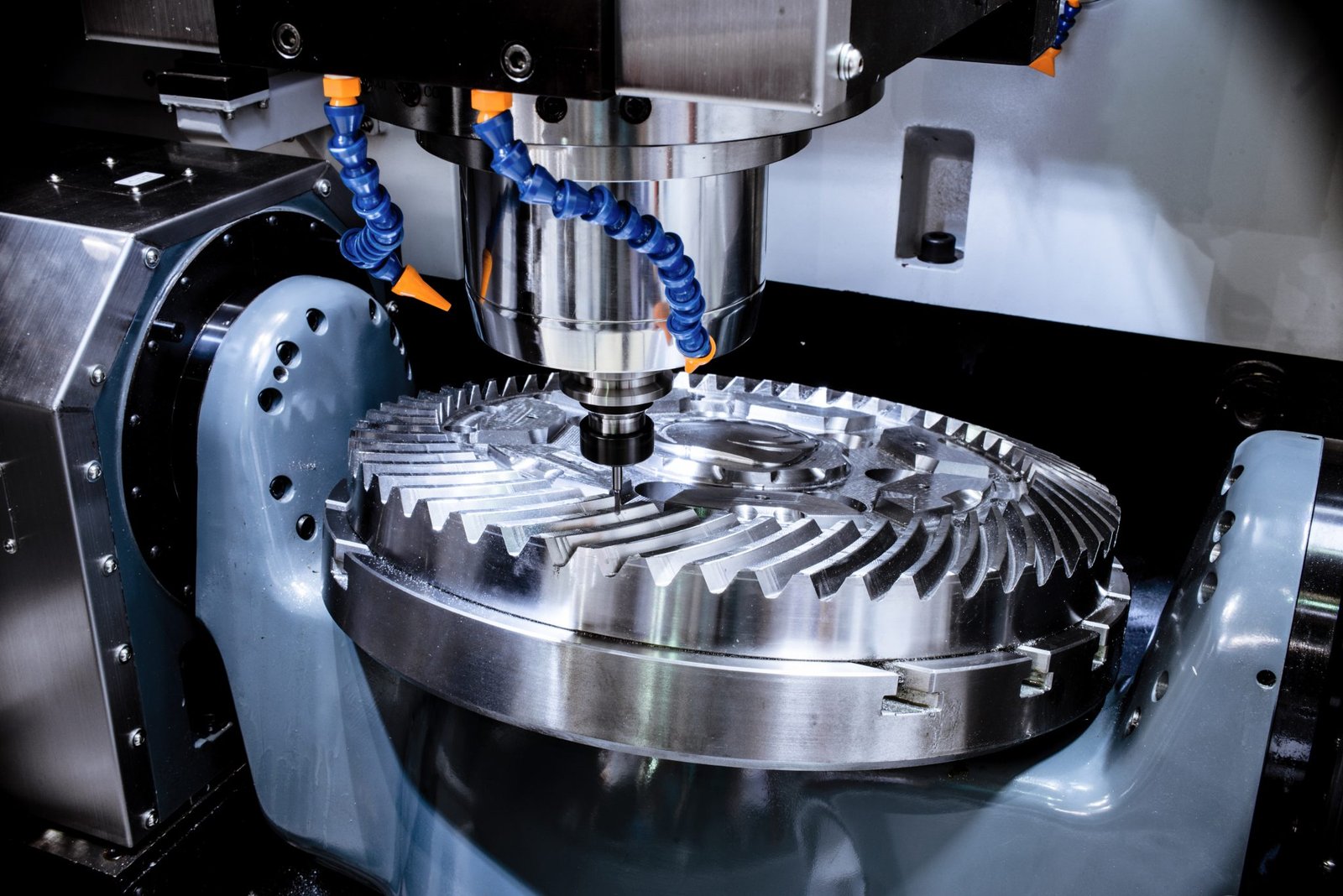
Mirror Sinker EDM
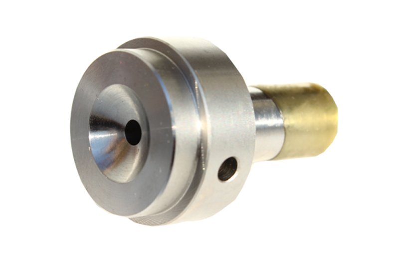
Mitsubishi mirror-grade sinker EDM produces deep cavities, intricate ribs and conformal cooling channels in PCS mold components with Ra 0.1um surface finish, eliminating secondary polishing and ensuring consistent part release across high-volume production runs.

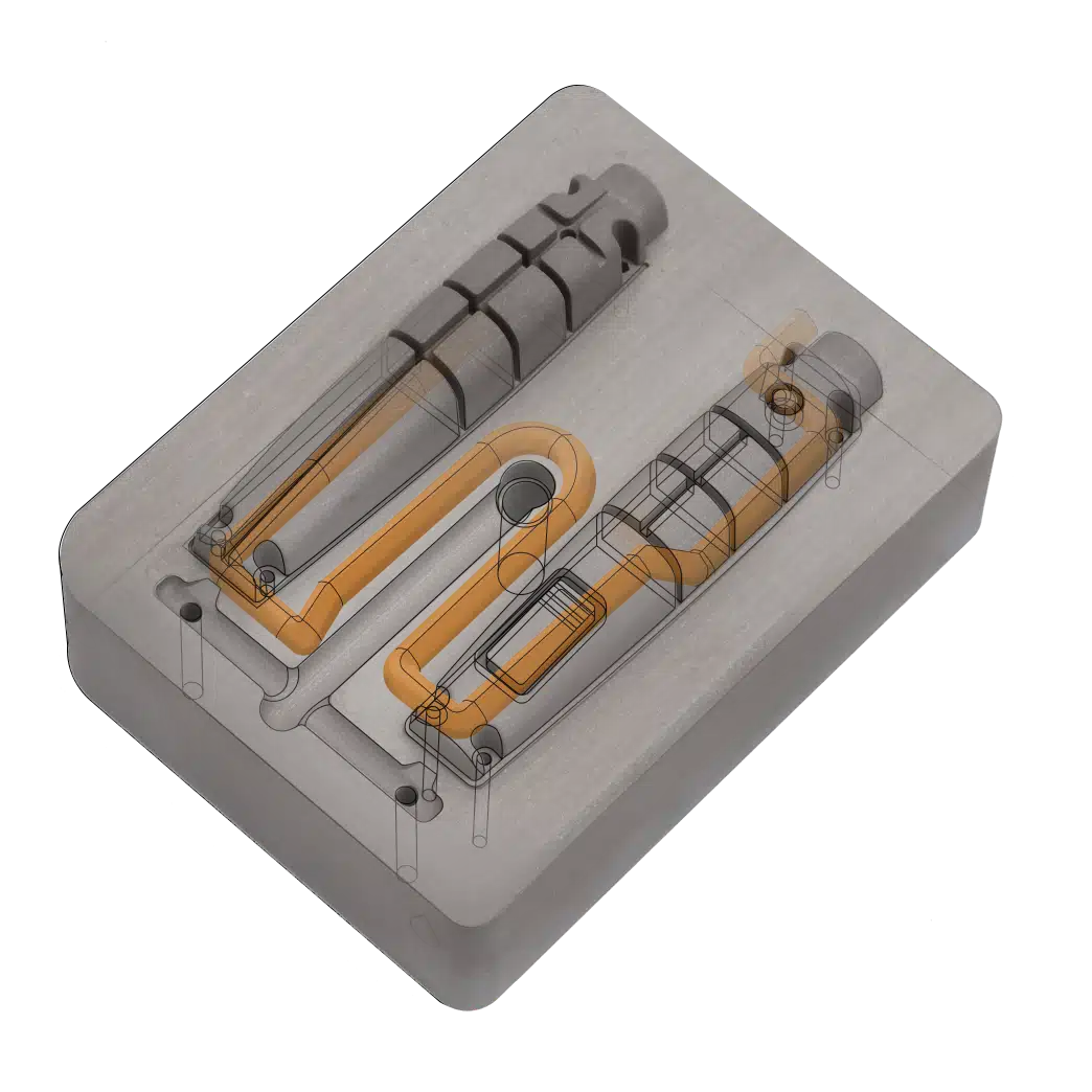
Conformal Cooling
Advanced conformal cooling channel design and machining reduce cycle times by up to 30 percent, eliminate hot spots and warpage, and extend mold life in high-volume automotive, 5G connector and medical-device applications requiring tight dimensional control.
Finishing & Assembly Options for Precision Tooling

Mirror-Grade Polishing
Ra 0.1 µm mirror EDM finishes on PCS mold components using Mitsubishi mirror EDM and precision hand-lapping. Ideal for optical housings, cosmetic surfaces and high-gloss injection tooling where surface integrity drives part performance.
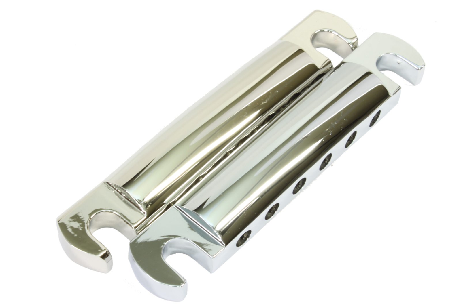
Nickel & Chrome Plating
Electroless nickel, hard chrome and decorative chrome plating for wear resistance, corrosion protection and extended tool life. Applied to ejector pins, core inserts and slider components in automotive, medical and 5G connector molds.
Full FAI Documentation
First Article Inspection reports with ZEISS MICURA CMM data, dimensional call-outs and tolerance verification for every critical feature. Includes full traceability, process sign-off and engineer approval — standard with every PCS mold component order.
Material Certificates
Mill test reports, spectral analysis and material traceability certificates for NAK80, S136, H13, SKD61, tungsten carbide and tool steels. Ensures compliance with OEM material specifications and regulatory requirements in medical, automotive and aerospace applications.
About XUXIANG — 16 Years of PCS Mold Components
Founded in 2010 in Dongguan’s Chang’an manufacturing hub, XUXIANG has grown from a specialist mold-core machining shop into a dual-factory precision group serving electronics, 5G/telecom, automotive & NEV, industrial-automation and medical-device customers worldwide. Over 16 years we have invested more than CNY 8 million in Japanese, Swiss and German equipment — Sodick slow-wire EDM, Mitsubishi mirror EDM, Fanuc CNC and ZEISS MICURA CMM metrology — to deliver PCS mold components held to +/-0.001 mm and mirror-grade Ra 0.1um finishes.
Our dual-site footprint — a 2,000 m² Dongguan R&D and micro-machining center plus a 1,400 m² Quanzhou volume-production facility launched in 2025 — has lifted annual capacity by 200 percent while maintaining micron-stable precision. Every PCS mold component is validated through five-step QC, backed by DFM engineering from 10+ experts, full FAI documentation and material certificates, all governed by ISO 9001:2015.
We solve the two biggest pain points in precision tooling: tolerance failure and delivery delay. With lead times 30 percent faster than the industry average — 3 to 7 days for samples, 15 to 25 days for mass production, and quotes returned within 24 hours — XUXIANG bridges the gap between complex CAD designs and high-performance physical parts, delivering dependable quality, responsive service and transparent pricing on every project.
About XUXIANG — 16 Years of Precision Mold Manufacturing
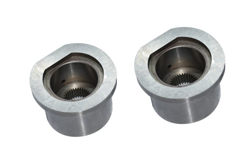
Micron-Stable Machining Precision
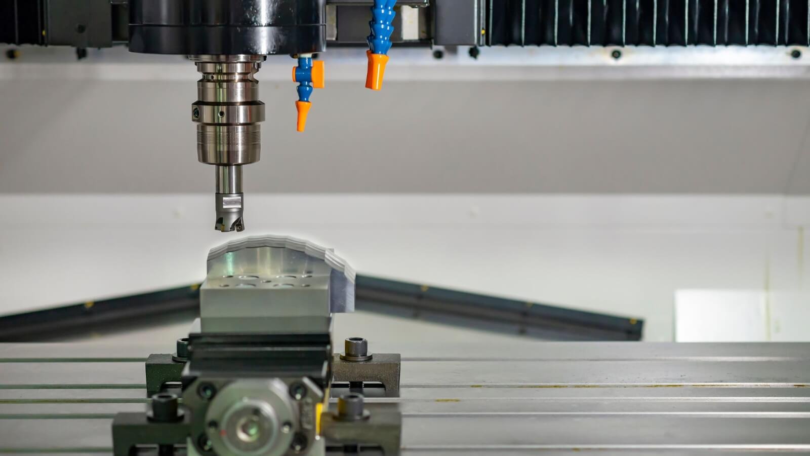
Every PCS mold component is machined to a maximum tolerance of +/-0.001 mm, ensuring dimensional stability across high-volume production runs. Sodick slow-wire EDM and Fanuc CNC systems deliver repeatable accuracy for complex core inserts, lifters and micro-connector tooling.
- +/-0.001 mm maximum machining tolerance on all critical dimensions
- Sodick & Seibu slow-wire EDM holds +/-0.002 mm class positioning
- Corner radii down to R ≤ 0.015 mm for micro-feature tooling
- Fanuc CNC and Beijing Jingdiao electrode fabrication for complex geometries
Mirror-Grade EDM Surface Finish
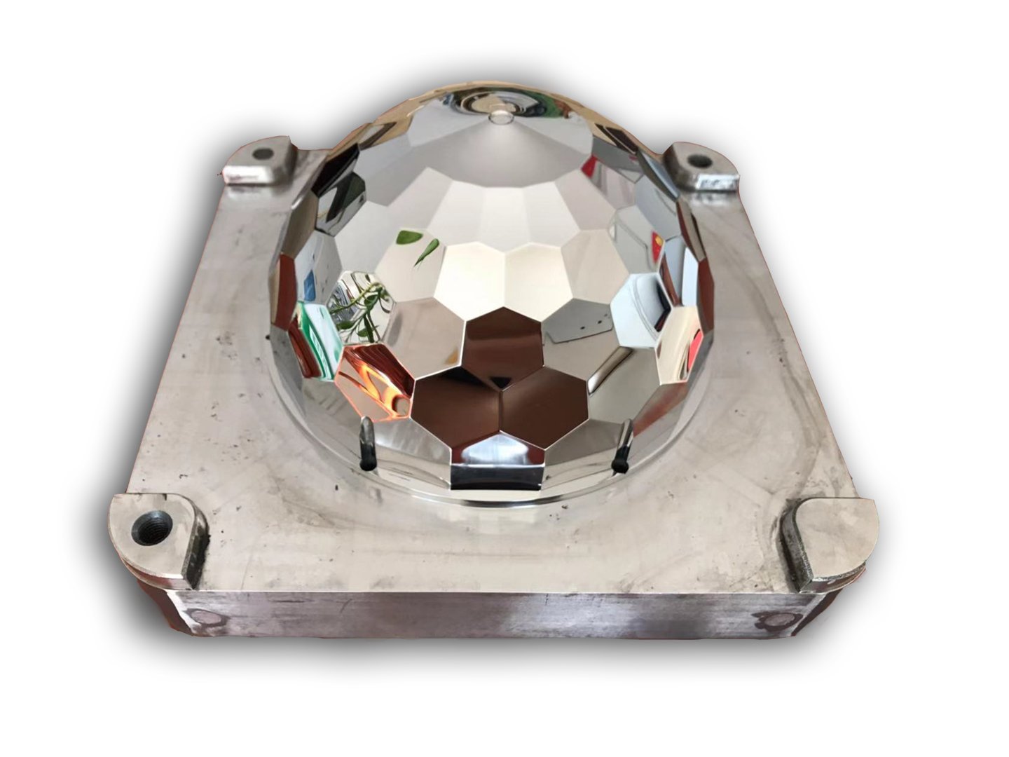
Mirror-class electrical discharge machining achieves Ra 0.1um surface finishes on cavity faces, eliminating secondary polishing and reducing cycle time. Mitsubishi mirror EDM and Sodick sinker systems produce optical-quality surfaces for high-gloss molded parts and micro-connector terminals.
- Ra 0.1um mirror-grade finish on EDM cavity surfaces
- Mitsubishi mirror EDM and Sodick sinker EDM for optical-class tooling
- +/-0.003 mm EDM accuracy on complex 3D contours
- Eliminates hand-polishing, shortens lead time and ensures consistency
ZEISS MICURA CMM Metrology
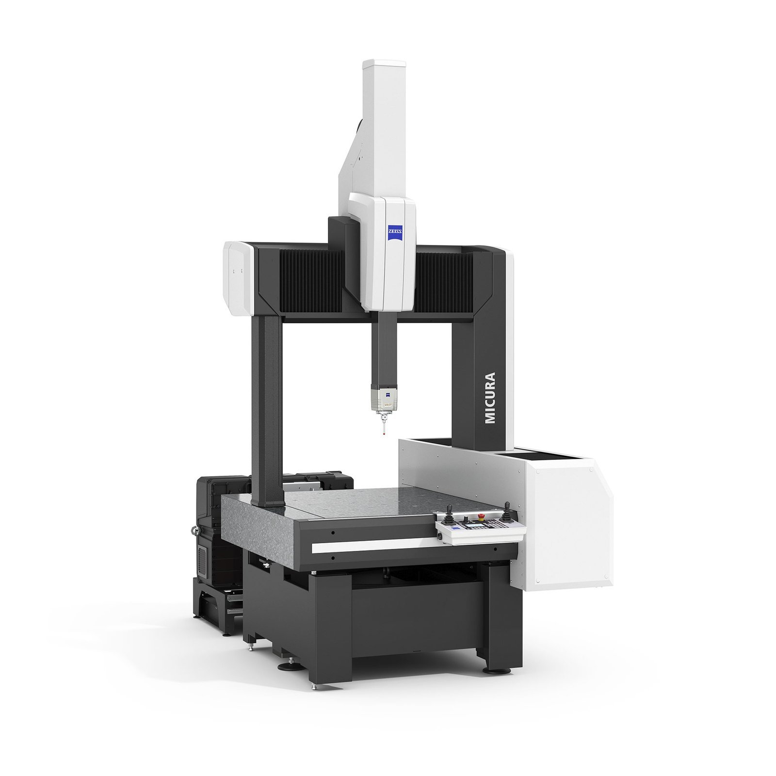
A ZEISS MICURA coordinate measuring machine with 0.7um resolution validates every critical dimension before shipment. Combined with Nikon V-12B and MM-400 class toolmaker’s microscopes, our metrology lab delivers traceable, certified inspection data with full FAI reports and material certificates.
- ZEISS MICURA CMM measuring to 0.7um resolution
- Nikon V-12B / MM-400 class toolmaker's microscopes for micro-features
- Full FAI documentation with dimensional reports and material certificates
- Five-step QC flow: spectral analysis, in-process monitoring, CMM verification, surface checks, final sign-off
DFM Engineering Support
Before production begins, 10+ engineering experts review your CAD files for manufacturability, tolerance optimization and cost reduction. DFM feedback identifies potential molding defects, draft angles, ejection risks and tooling wear points—so your PCS mold components perform reliably from the first shot.
- Pre-production DFM review by 10+ precision-tooling engineers
- Tolerance optimization, draft-angle analysis and ejection-path validation
- Proactive identification of molding defects and tooling wear risks
- Collaborative design iteration to balance performance, cost and lead time
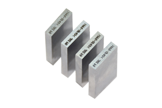
Core Capabilities: Micron-Scale Precision Tooling
Evidence-based differentiation: precision equipment, dual-factory capacity, and engineering support that solves tolerance failure and delivery delay.
← 左右滑动查看 →
Our PCS Mold Components Production Workflow
Every PCS mold component moves through a five-phase quality system — from DFM engineering feedback to final FAI documentation — ensuring micron-stable precision, on-time delivery and full material traceability.
DFM Review & Engineering Feedback
10+ engineering experts analyze your CAD files, flag tolerance risks, recommend machining strategies and optimize geometries for manufacturability before production begins.
CNC & EDM Fabrication
Sodick slow-wire EDM, Mitsubishi mirror EDM and Fanuc CNC machines execute +/-0.001 mm machining precision with in-process tolerance monitoring on every PCS mold component.
ZEISS CMM & Surface Verification
ZEISS MICURA CMM measures to 0.7um accuracy; Nikon toolmaker’s microscopes validate surface integrity, corner radii and Ra 0.1um mirror finishes across critical features.
FAI Documentation & Material Certificates
Every batch ships with full First Article Inspection reports, spectral material analysis certificates and dimensional inspection records — complete traceability for ISO compliance.
Quality-Assured Shipment
Parts are cleaned, individually packaged to prevent handling damage and shipped with full documentation — samples in 3-7 days, mass production in 15-25 days.
Our Precision Tooling Production Workflow
From CAD upload to certified delivery, our streamlined five-step process ensures micron-stable precision, transparent communication and on-time fulfillment for every PCS mold components order.
Submit Your Technical Package
Upload CAD drawings, 3D models or technical specifications via our online portal or email. Include material requirements, tolerance zones and finish expectations.
Receive Quote & DFM Feedback
Within 24 hours, our engineering team delivers a detailed quote plus DFM recommendations from 10+ precision-mold experts to optimize manufacturability and cost.
Approve Samples in 3–7 Days
We machine first-article samples on Sodick slow-wire EDM and ZEISS MICURA CMM, providing full dimensional reports and surface-finish validation before mass production.
Bulk Production in 15–25 Days
ISO 9001:2015 five-step QC monitors every part through in-process tolerance checks, ensuring +/-0.001 mm accuracy and Ra 0.1um mirror finishes at volume.
Delivery with FAI & Certificates
Every shipment includes complete FAI documentation, material spectral-analysis certificates and ZEISS/Nikon inspection reports, ready for your incoming quality assurance.
How to Partner with XUXIANG for Precision Tooling


PCS Mold Components: Real Results from Global OEM & Tier Suppliers
XUXIANG delivered our 8-cavity micro-connector core inserts to +/-0.002 mm across all positions. We reduced scrap by 42% in the first production run and hit our quality gate two weeks ahead of schedule.
Their PCS mold components for our ADAS sensor housings maintained Ra 0.12um surface finish over 50,000 cycles. Lead time was 18 days versus our previous supplier’s 35 days, with full FAI documentation on delivery.
We needed mirror-EDM lifters with R 0.015 mm corner radii for a medical-device mold. XUXIANG’s ZEISS CMM report confirmed 0.0008 mm deviation. Sample delivered in 5 days, production lot in 22 days — flawless.
Precision Tooling: Real Results from Global OEM & Tier Suppliers
What is the minimum order quantity (MOQ) for PCS mold components?
What are the lead times for sample and bulk orders of PCS mold components?
Do you charge for sampling, and are sample fees refundable?
What payment terms do you offer for PCS mold components orders?
How do you handle shipping, customs documentation, and import duties for PCS mold components?
How do you protect intellectual property (IP) and confidential designs for PCS mold components?
Can you guarantee the dimensional tolerances specified in my drawings for PCS mold components?
Where do you source raw materials for PCS mold components, and do you provide material certificates?
Do you offer design-for-manufacturing (DFM) support for custom PCS mold components?
FAQ — Precision Tooling, Tolerances & Delivery
Navigate supplier selection with confidence. This guide delivers a proven decision framework, critical quality criteria, material comparisons, and the five most costly mistakes procurement teams make when sourcing pcs mold components for high-precision mold tooling.
1. What Are PCS Mold Components?
PCS mold components are precision-machined inserts, cores, cavities, lifters, sliders and ejector pins engineered to hold tolerances of +/-0.001 to +/-0.003 mm across injection-molding cycles. In high-density micro-connector tooling, 5G RF housings and automotive sensor enclosures, a single micron of drift can cause pin misalignment, flash or short-shot defects — making dimensional stability the defining performance metric.
These components form the active geometry of the mold: cavity inserts shape the outer surface, core pins define internal features, and slides enable undercuts. For example, a board-to-board connector mold may contain 30+ micro-pins machined to corner radii of R ≤ 0.015 mm, each requiring mirror-grade EDM finish (Ra 0.1 µm) and positioning accuracy within +/-0.002 mm to ensure reliable terminal insertion over 500,000+ cycles.
Buyers prioritize pcs mold components because tooling failure — whether from thermal distortion, wear or poor surface integrity — halts production, triggers costly rework and delays product launch. Validated dimensional control, traceable material certificates and CMM inspection reports are non-negotiable in electronics, automotive and medical supply chains.
2. Evolution of PCS Mold Components in Precision Manufacturing
Before 2000, most mold components were machined to +/-0.02 mm tolerances using conventional milling and manual EDM, adequate for consumer housings but insufficient for today’s micro-connectors and sensor arrays. The advent of five-axis CNC machining and sub-micron slow-wire EDM in the early 2000s pushed achievable precision to +/-0.005 mm, enabling the first generation of smartphone tooling and miniaturized medical devices.
Between 2010 and 2020, three forces reshaped pcs mold components: smartphone miniaturization demanded +/-0.002 mm class positioning for board-to-board and FPC connectors; 5G infrastructure required high-frequency RF tooling with mirror finishes below Ra 0.2 µm to minimize signal loss; and automotive electrification introduced ADAS sensors and battery-management-system interconnects that could not tolerate dimensional drift beyond +/-0.001 mm. Material science followed suit — premium H13 and SKD61 tool steels gave way to nitrided NAK80 and beryllium-copper alloys optimized for thermal stability and wear resistance.
Today, ZEISS CMM verification to 0.7 µm resolution and mirror-grade EDM finishes down to Ra 0.1 µm define the precision floor for tier-one suppliers serving electronics, telecom and NEV markets.
3. Core Types of PCS Mold Components
Precision molding relies on six core component families, each engineered to specific tolerance bands and application demands. Understanding the function and fit of ejector pins, core pins, inserts, guide pillars, sleeves and locating rings ensures you specify the right part for cavity count, cycle time and product geometry.
Ejector Pins
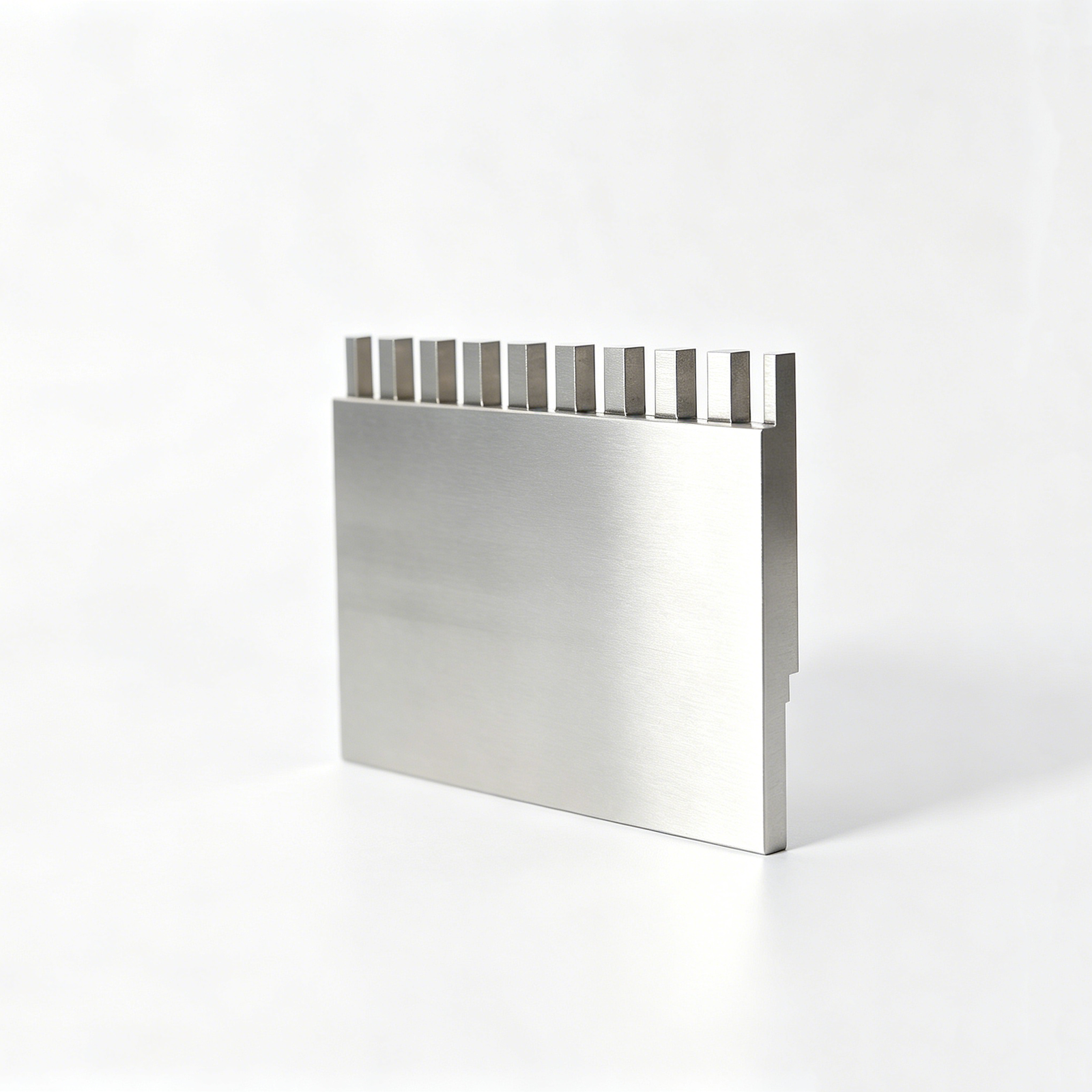
Ejector pins push finished parts out of the mold cavity after cooling. Standard tolerance is +/-0.01 mm; high-cycle electronics and micro-connector molds demand +/-0.005 mm or tighter to prevent flash and part distortion.
XUXIANG machines ejector pins to +/-0.002 mm on Sodick slow-wire EDM, validated by ZEISS CMM, ensuring consistent ejection across 100,000+ cycle runs in automotive sensor housings and 5G terminal tooling.
Core Pins and Inserts
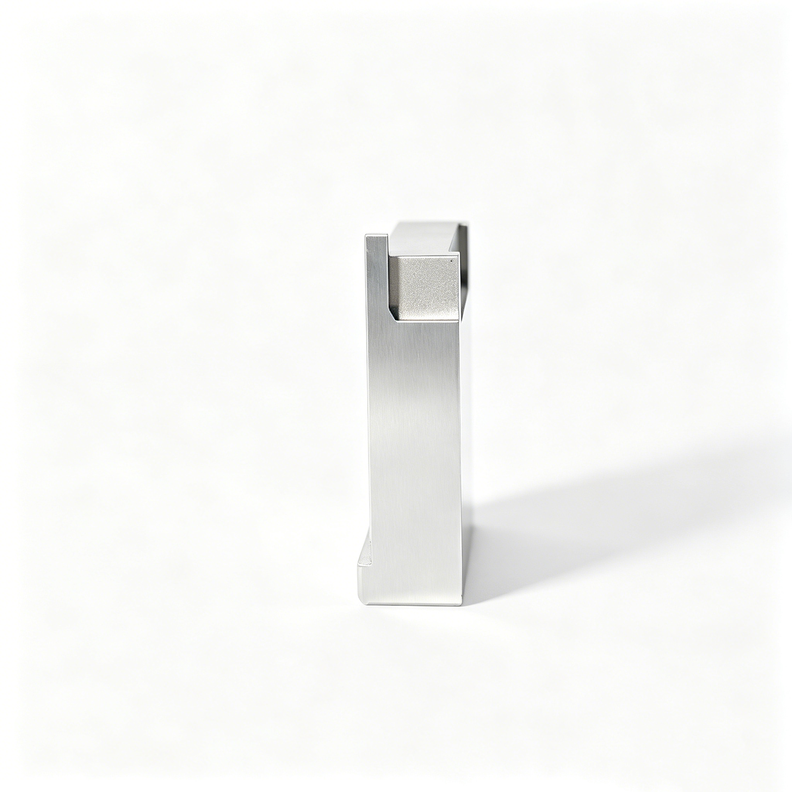
Core pins form internal features — holes, threads, undercuts — while inserts define cavity surfaces. Tolerances range from +/-0.01 mm for general plastics to +/-0.002 mm for multi-cavity micro-connector cores.
Mirror-grade EDM finishes (Ra 0.1 µm) and conformal cooling channels are common in high-volume NEV battery-management-system tooling, where thermal stability drives cycle-time reduction.
Guide Pillars and Bushings
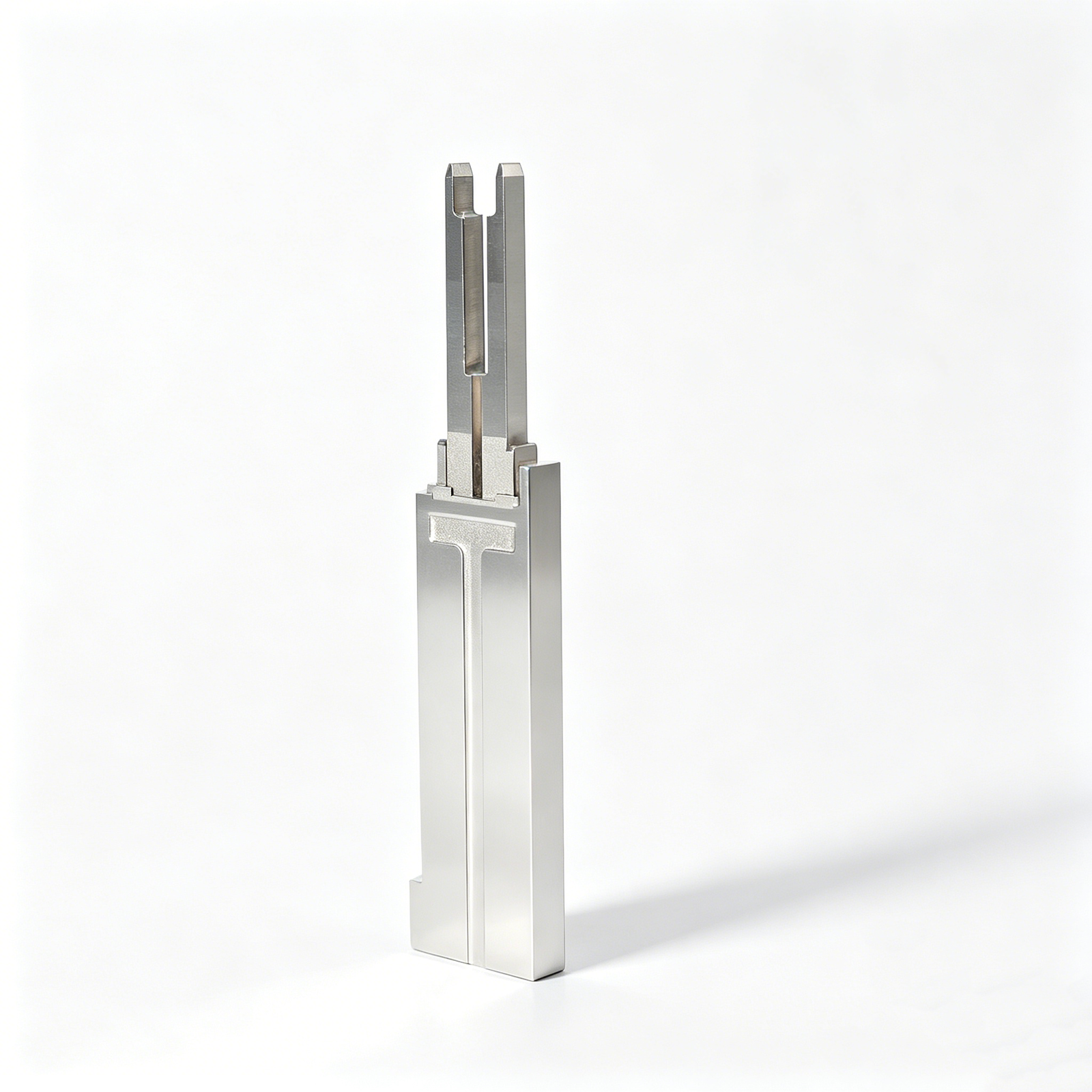
Guide pillars align mold halves; bushings reduce friction and wear. Precision-ground to +/-0.003 mm, they maintain micron-level cavity registration over millions of cycles.
Industrial-automation and robotics jigs specify hardened steel (HRC 58–62) and nitrided surfaces to withstand high-speed injection pressures without deflection.
Sleeves and Locating Rings
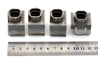
Sleeves protect core pins from thermal shock and abrasion; locating rings center the mold on the machine platen. Both hold +/-0.005 mm positional tolerance to ensure nozzle alignment and prevent short shots.
Medical-device and micro-optics molds often require custom sleeve materials — beryllium copper or tool steel with PVD coatings — to manage heat dissipation and contamination control.
4. Materials Used in PCS Mold Components
Material selection drives dimensional stability, tool life and per-part economics across every pcs mold components program. XUXIANG’s engineering team matches alloy hardness, thermal conductivity and wear resistance to cycle count, fill pressure and resin chemistry — ensuring the component survives its intended environment without over-specifying cost.
| Material | Hardness | Typical Application | Relative Cost |
|---|---|---|---|
| SKH-51 | HRC 62–64 | Micro-connector cores, mirror EDM | Medium |
| SKD61 | HRC 48–52 | High-volume inserts, lifters | Low |
| ASP23 | HRC 60–62 | Glass-filled resins, NEV sensors | High |
| Tungsten Carbide | HRA 88–92 | Gate lands, thin-wall pins | Very High |
| TiN / TiCN / DLC | HV 2,300–3,000 | Ejector pins, slides, hot runners | Coating premium |
Steel Alloys: SKH-51, SKD61 and ASP23
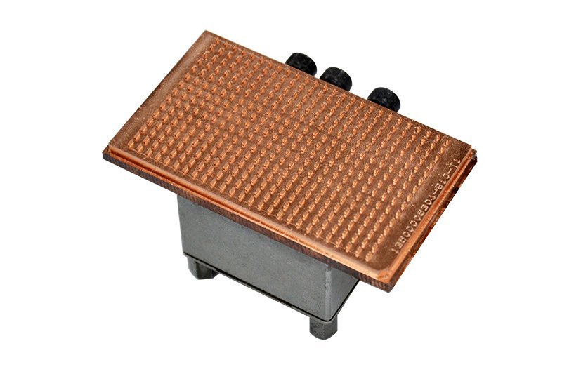
SKH-51 (high-speed tool steel) reaches HRC 62–64 after heat treatment, offering sharp corner retention and mirror-finish EDM for micro-connector cores. SKD61 (hot-work die steel) balances toughness at HRC 48–52 with superior thermal conductivity, making it the workhorse for high-volume automotive inserts and lifters.
ASP23 powder-metallurgy steel delivers HRC 60–62 with exceptional wear resistance and dimensional stability under abrasive glass-filled resins, ideal for NEV sensor housings and ADAS terminal tooling where tolerances cannot drift beyond +/-0.002 mm over millions of cycles.
Tungsten Carbide for Ultra-High-Wear Zones
Tungsten carbide inserts (HRA 88–92) extend life 5–10× in gate lands, ejector pins and thin-wall micro-pins subject to severe abrasion. XUXIANG machines carbide on Sodick slow-wire EDM with dedicated diamond-wire setups, holding corner radii to R ≤ 0.015 mm and positional tolerance +/-0.002 mm, then validates geometry on the ZEISS MICURA CMM to ensure carbide inserts seat flush within steel cavities.
Specialty Coatings: TiN, TiCN and DLC
TiN (titanium nitride) adds surface hardness to HV 2,300 and reduces friction on ejector systems. TiCN coatings push hardness to HV 3,000 with better oxidation resistance for hot-runner manifolds. DLC (diamond-like carbon) delivers the lowest coefficient of friction for micro-connector slides and high-speed ejection, preventing galling on sub-0.3 mm pins where even micron-scale wear causes flash or sticking.
5. Precision Tolerances and Quality Standards for PCS Mold Components
Precision-grade pcs mold components live or die by tolerance and surface integrity. Understanding the numeric bands, certification requirements and inspection protocols separates reliable tooling from costly rework cycles.
Tolerance Bands for Precision-Grade Components
Standard precision mold work holds ±0.005 mm; high-precision parts demand ±0.002 mm; ultra-precision applications — micro-connectors, medical inserts — require ±0.001 mm. XUXIANG’s slow-wire EDM and ZEISS MICURA CMM (0.7 µm resolution) routinely deliver ±0.001 mm on critical dimensions.
Buyers should specify tolerances per feature: core-pin diameter, cavity depth, parting-line flatness. Over-specifying every dimension inflates cost; under-specifying risks assembly failure.
Quality Certifications and Standards
ISO 9001:2015 governs general mold-component manufacturing. Medical-device tooling requires ISO 13485 traceability; automotive molds demand IATF 16949 for PPAP and control plans. XUXIANG operates under ISO 9001:2015, with full material certificates and FAI documentation for every shipment.
Inspection Methods and Surface-Finish Specs
CMM (coordinate measuring machine) verification is mandatory for ±0.005 mm or tighter work; optical toolmaker’s microscopes (Nikon V-12B class) validate edge radii and micro-features. Surface finish ranges from Ra 0.1 µm (mirror EDM) to Ra 0.8 µm (standard grinding). Buyers should audit supplier CMM calibration certificates and request in-process inspection reports.
6. Customization Options for PCS Mold Components
Most precision tooling projects require custom geometries, material grades or surface treatments beyond catalog offerings. XUXIANG’s engineering team provides DFM collaboration before production, tailoring pcs mold components to match CAD specifications, thermal-management requirements and production-volume targets.
Custom Geometries and Proprietary Coatings
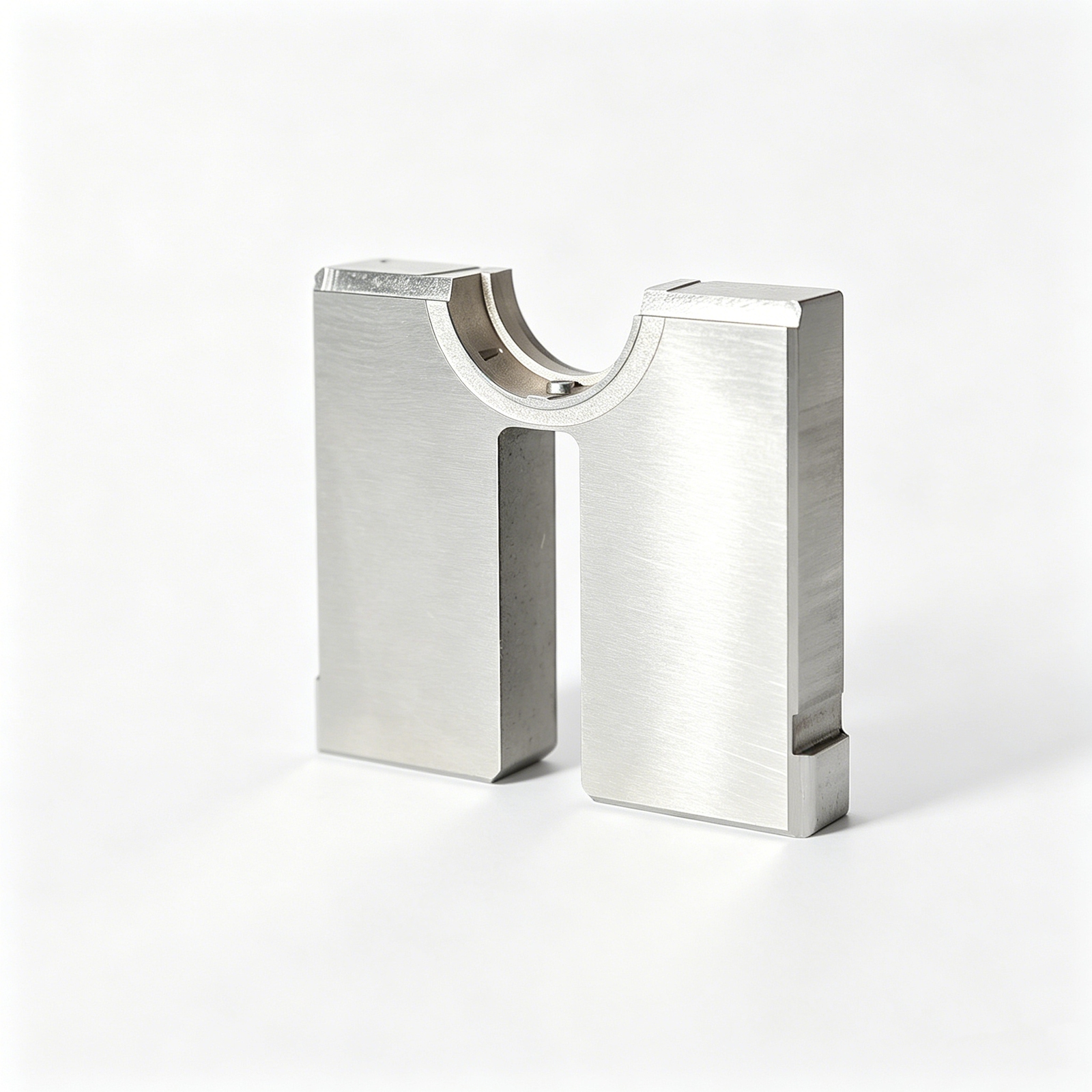
Complex cavity inserts, conformal cooling channels and micro-connector pins are machined to customer-supplied 3D models, with slow-wire EDM holding +/-0.002 mm positioning and corner radii down to R 0.015 mm. Proprietary PVD or nitriding treatments extend wear life in high-cycle applications.
Laser engraving adds serial numbers, date codes or QR traceability directly onto core surfaces without affecting dimensional integrity, meeting automotive and medical traceability standards.
Design-for-Manufacturability Collaboration
XUXIANG’s 10+ engineering experts review every design file for machinability, draft angles and ejection clearances before toolpath generation. DFM feedback reduces rework cycles and shortens lead times by approximately 30% versus industry averages, ensuring first-article parts meet tolerance and surface-finish specifications.
Lead Times, MOQ and When Standard Parts Suffice
Custom machining typically requires 10–15 working days; rush orders with expedited EDM scheduling deliver in 7 days. Minimum order quantities start at single-piece prototypes for validation, scaling to production runs of 50–500+ units.
Standard catalog ejector pins or guide bushings suit low-precision applications; custom engineering adds value when tolerances tighten below +/-0.01 mm or when proprietary geometries demand mirror-grade EDM finishes.
7. How to Choose a PCS Mold Components Manufacturer
Selecting a pcs mold components supplier requires auditing machining depth, metrology infrastructure and service responsiveness. A robust capability stack—5-axis CNC, slow-wire EDM, precision grinding and in-house CMM—signals the ability to hold +/-0.002 mm tolerances and deliver on time.
Machining and Tooling Capabilities
Verify that the shop operates Sodick or Charmilles sinker EDM, Seibu or Sodick slow-wire EDM, and 5-axis CNC milling under one roof. Multi-process integration eliminates handoff delays and tolerance stack-up.
Ask for corner-radius minimums (R ≤ 0.015 mm is precision-grade), wire-EDM repeatability (+/-0.002 mm class) and electrode-fabrication capability. Shops relying on outsourced wire or grinding cannot guarantee end-to-end traceability.
In-House Inspection and Certification
Demand access to CMM reports from ZEISS, Mitutoyo or equivalent systems with sub-micron resolution. Nikon toolmaker’s microscopes (V-12B class) and spectral analyzers confirm material compliance and surface finish down to Ra 0.1 µm.
ISO 9001:2015 certification is baseline; look for documented five-step QC flows—material analysis, in-process monitoring, CMM verification, surface checks and FAI with material certificates.
Lead-Time Guarantees and Logistics
Standard lead times for precision pcs mold components range 15–25 days; best-in-class suppliers deliver 30 % faster through optimized scheduling and dual-factory capacity. Confirm whether DFM feedback is included pre-production and whether the vendor maintains safety stock for repeat orders.
Technical Support and Partnership Model
Evaluate whether the supplier assigns a dedicated engineering contact for tolerance queries, material substitutions and design revisions. Post-delivery support—warranty terms, rework policies and on-site troubleshooting—separates transactional vendors from long-term partners capable of scaling with your program.
8. Common Mistakes Buyers Make When Sourcing PCS Mold Components
Even experienced procurement teams fall into predictable traps when sourcing pcs mold components, driving up costs or risking production delays. Understanding these mistakes — and their consequences — protects both budget and timeline.
Over-Specifying Tolerances Beyond Functional Need
Calling out +/-0.001 mm when +/-0.005 mm suffices inflates machining time and cost by 40–60%. Tighter tolerances demand slow-wire EDM, additional grinding passes and extended CMM validation.
Align tolerance bands with actual mating requirements. XUXIANG’s DFM review flags over-specification before quoting, saving unnecessary expense.
Ignoring Material Hardness for the Application
Specifying SKD61 at HRC 48 for high-cycle injection tooling accelerates wear and premature core replacement. Conversely, over-hardening (HRC 58+) raises machining difficulty and lead time without performance gain.
Match hardness to cycle count and resin abrasiveness; consult supplier material datasheets and spectral analysis reports to verify heat-treatment compliance.
Neglecting Supplier Inspection Documentation
Accepting parts without CMM reports, material certificates or FAI packages leaves tolerance claims unverified. Downstream assembly failures traced to out-of-spec components cost 10× the original part price.
Demand ZEISS or equivalent CMM data, material spectral analysis and surface-finish readings with every shipment.
Underestimating Lead Times and Failing to Qualify Backup Suppliers
Single-source strategies and optimistic schedules create bottlenecks when demand spikes or tooling revisions arise. A sole supplier outage can halt production lines.
Build a qualified secondary source and pad lead times by 15–20% for complex pcs mold components to absorb unforeseen design iterations.
9. Pricing and Cost Structure for PCS Mold Components
Pricing for pcs mold components is driven by six measurable variables: material grade (H13 versus S136 versus tungsten carbide can swing unit cost 40–120%), tolerance band (+/-0.005 mm standard versus +/-0.001 mm precision adds 25–35% machining time), surface finish (Ra 0.8 µm mill finish versus Ra 0.1 µm mirror EDM), coating type (TiN, DLC or none), order quantity and expedited delivery (sub-10-day express adds 15–30%).
XUXIANG’s cost structure reflects real machining economics: setup (programming, electrode fabrication, first-article inspection) is amortized across the batch, so per-unit price drops sharply from 10-piece prototypes to 500-piece production runs. A typical core insert in NAK80, +/-0.002 mm tolerance, mirror finish, might run USD 85–120 at 10 pcs, USD 45–65 at 100 pcs and USD 28–38 at 500 pcs, with lead times compressing from 18 days to 12 days as volume rises and setup overhead spreads.
Buyers should request itemized quotes that separate material, machining, finishing and inspection so that value-engineering trade-offs — relaxing one tolerance zone, switching from full-mirror to semi-mirror — can be evaluated line by line.
| Quantity Tier | Price per Unit (USD) | Typical Lead Time |
|---|---|---|
| 10 pcs (prototype) | $85–120 | 16–18 days |
| 50 pcs (pilot) | $55–75 | 14–16 days |
| 100 pcs (low-volume production) | $45–65 | 12–14 days |
| 500 pcs (volume production) | $28–38 | 10–12 days |
10. Steps to Launch Your Precision Mold Project with PCS Mold Components
A disciplined procurement workflow reduces risk and accelerates time-to-production. The steps below outline how to move from initial RFQ to serial supply of pcs mold components with confidence.
Define Specifications and Tolerances
Document part geometry, material grade (e.g., NAK80, SKD61), tolerance class (+/-0.002 mm or tighter), surface finish (Ra ≤ 0.2 µm for mirror cores), and operating environment. Include 3D CAD (STEP or IGES) and 2D PDF drawings with GD&T callouts to eliminate ambiguity.
Request Quotes with Detailed Drawings
Submit RFQs to shortlisted suppliers with complete CAD files, material certificates and inspection-report expectations. XUXIANG’s engineering team provides DFM feedback within 24 hours, flagging manufacturability risks before quoting.
Evaluate Samples and Inspection Data
Request first-article samples with ZEISS CMM reports, material spectral analysis and surface-integrity scans. Compare measured dimensions against nominal tolerances; reject suppliers who skip metrology documentation.
Place Pilot Orders and Validate in Production
Order pilot quantities (5–20 pieces) for real-mold trials. Monitor cycle stability, part ejection and dimensional drift over 500+ cycles before committing to volume. Establish ongoing supply agreements with locked tolerances and delivery SLAs.
Ready to Source Precision PCS Mold Components?
Get your quote in 24 hours, DFM feedback from 10+ experts, and samples in 3–7 days with full FAI documentation.