
Precision Guide Bush & Mold Components — +/-0.001 mm Tolerance
ISO 9001:2015-certified guide bush manufacturing with ZEISS CMM validation, mirror-grade EDM finishing and quotes returned in 24 hours — engineered for electronics, automotive and connector tooling.
Featured Guide Bush & Mold Component Solutions
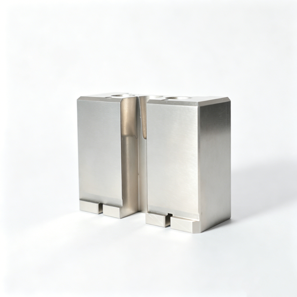
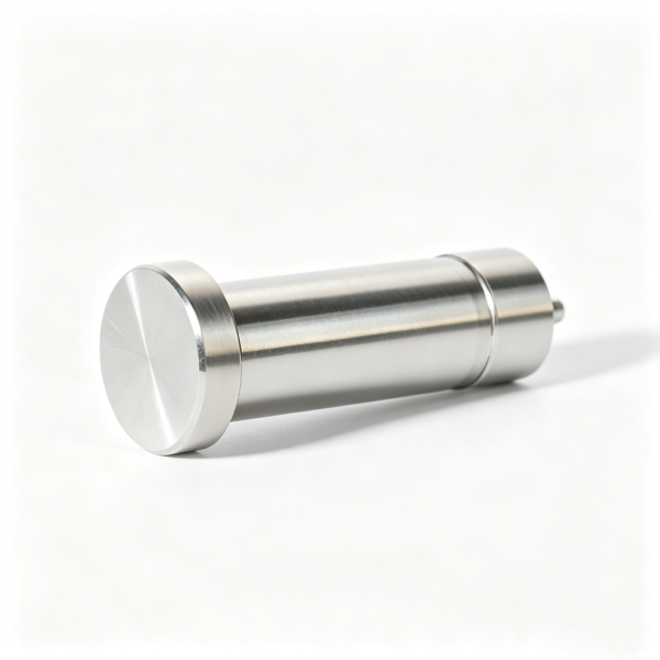
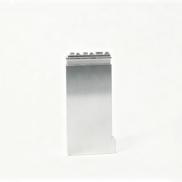
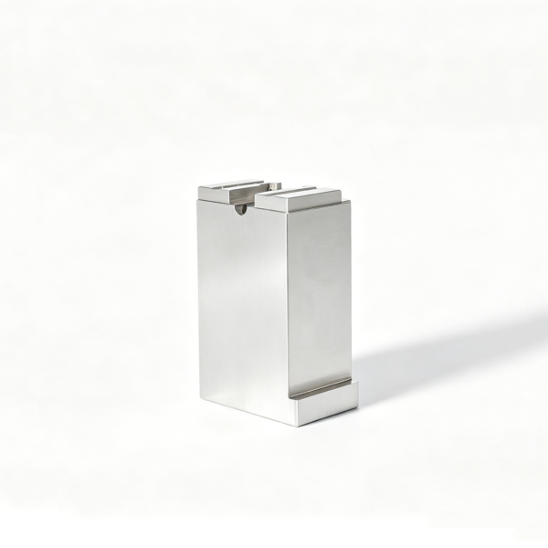
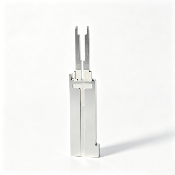
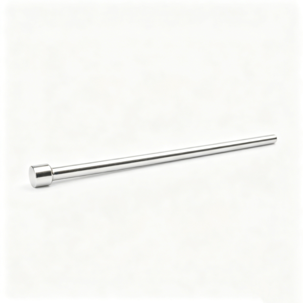
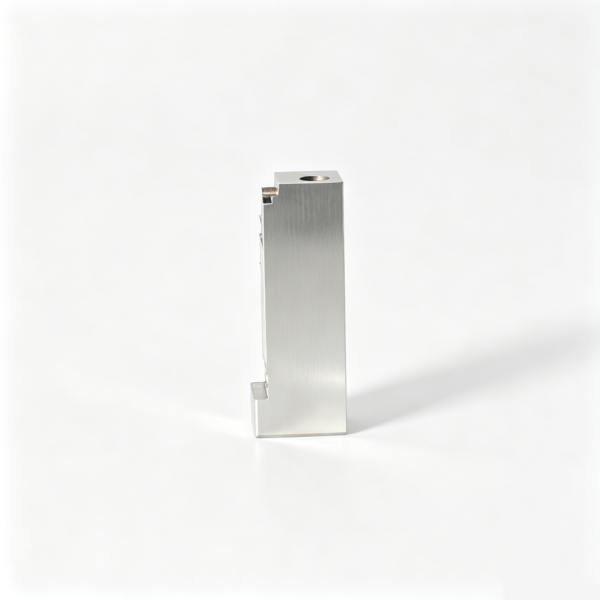
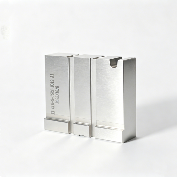
Guide Bush & Precision Mold Component Gallery
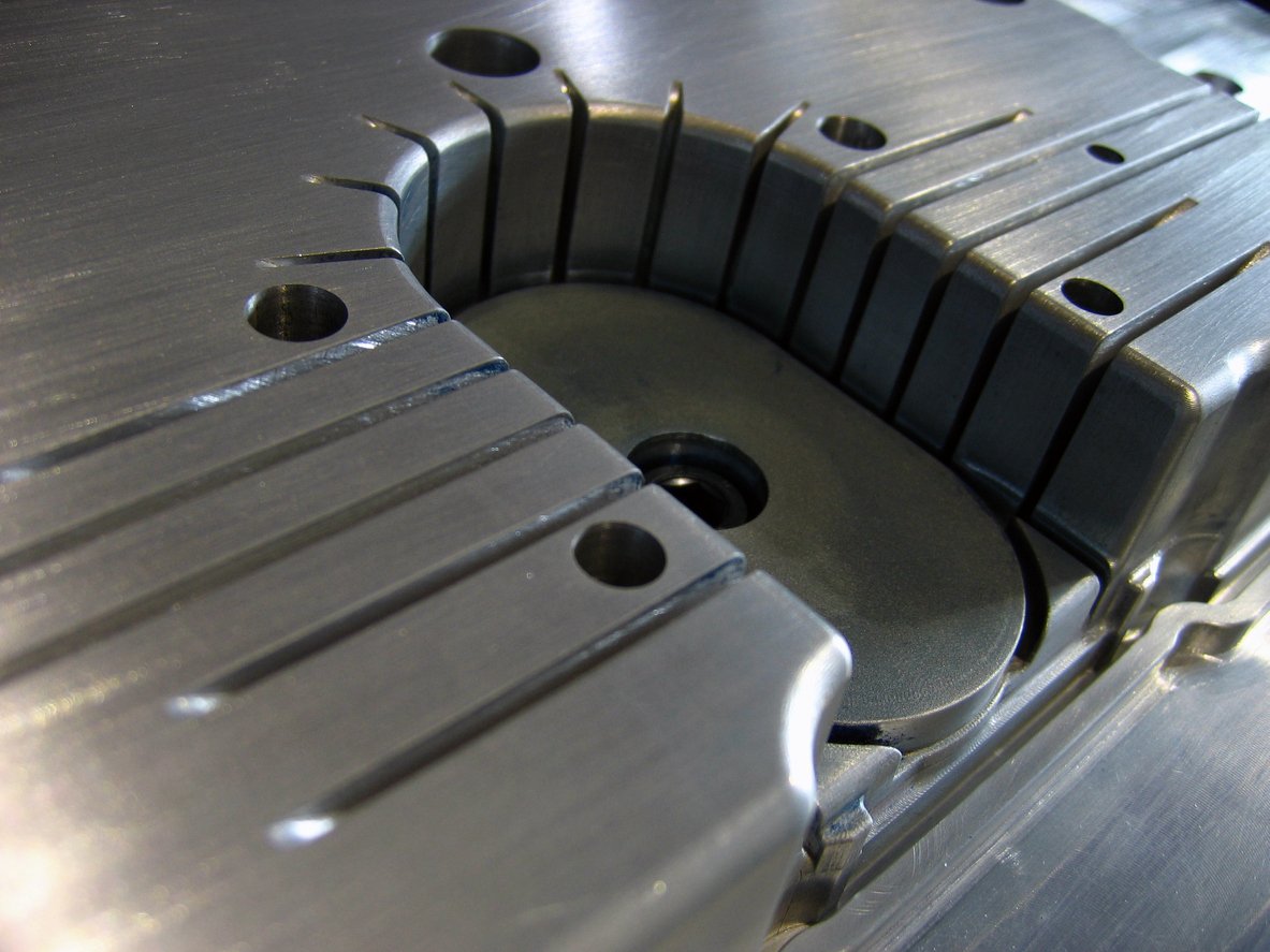

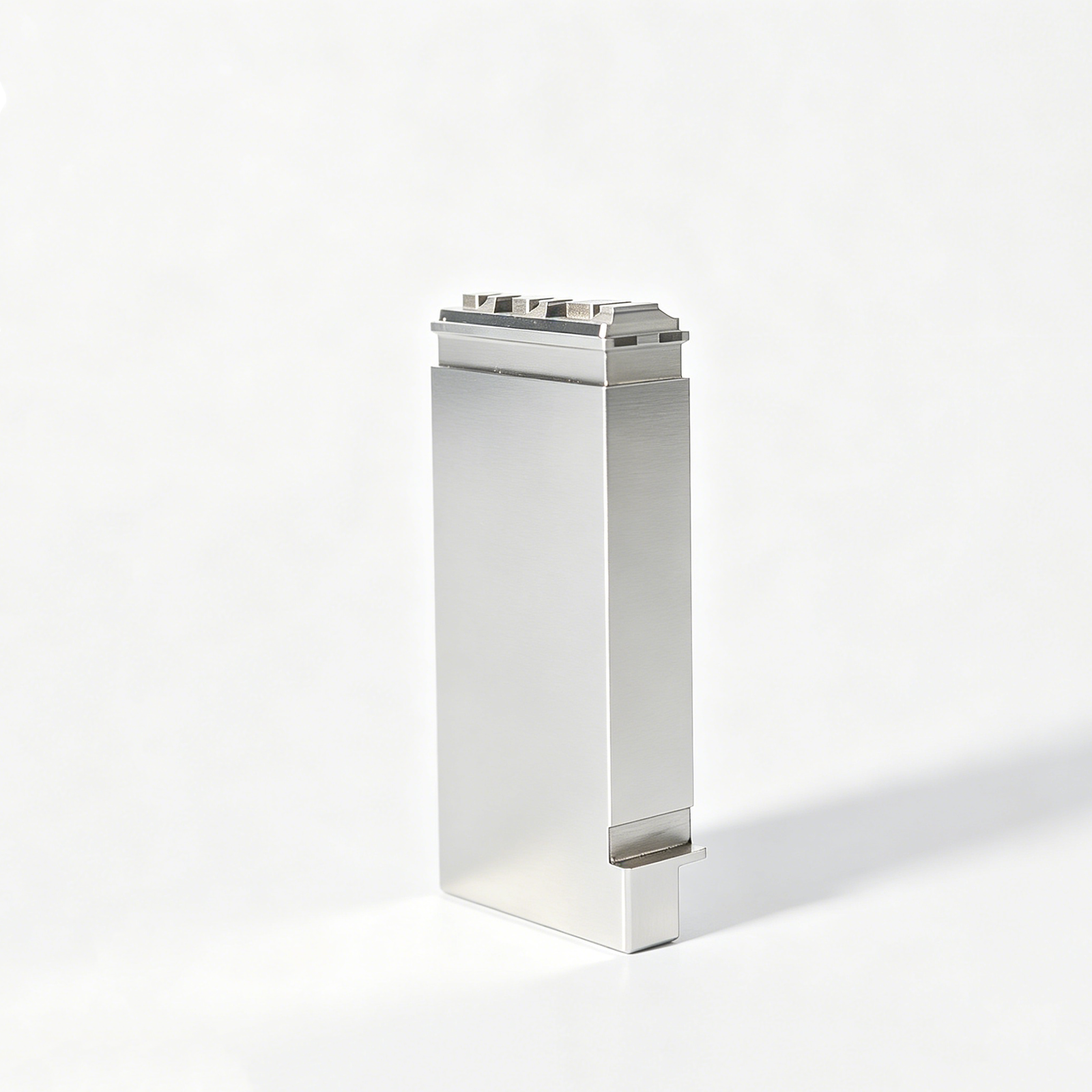
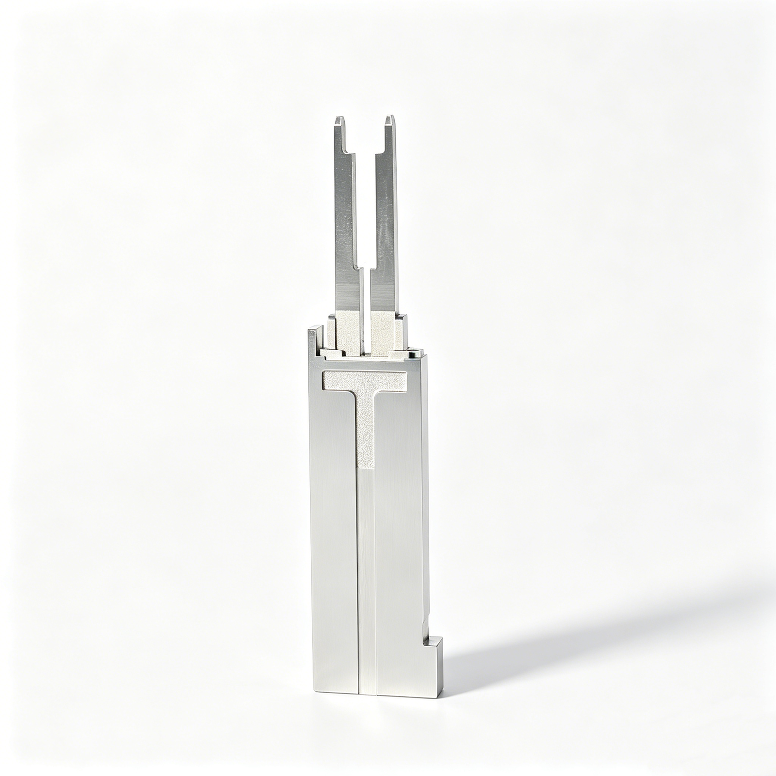
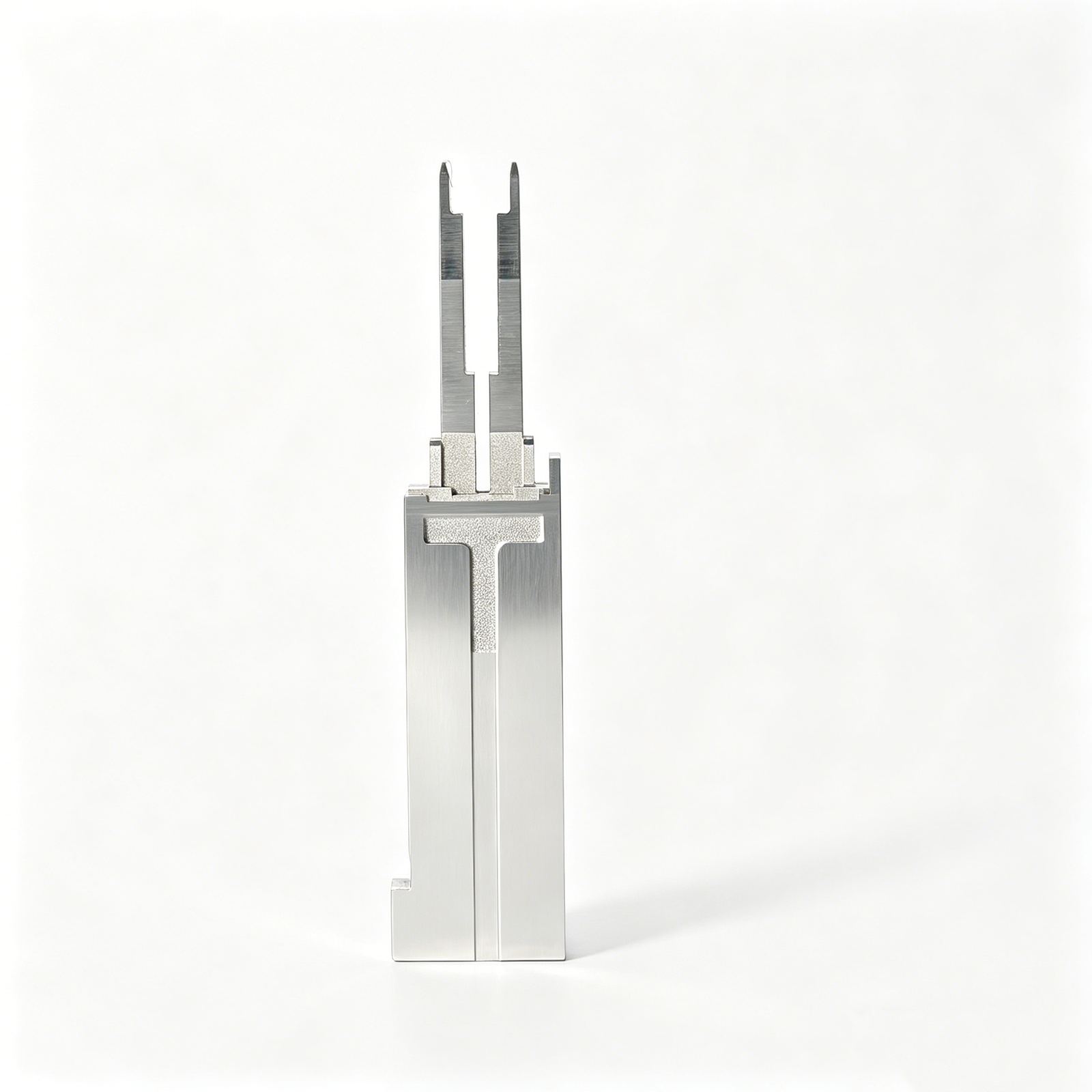
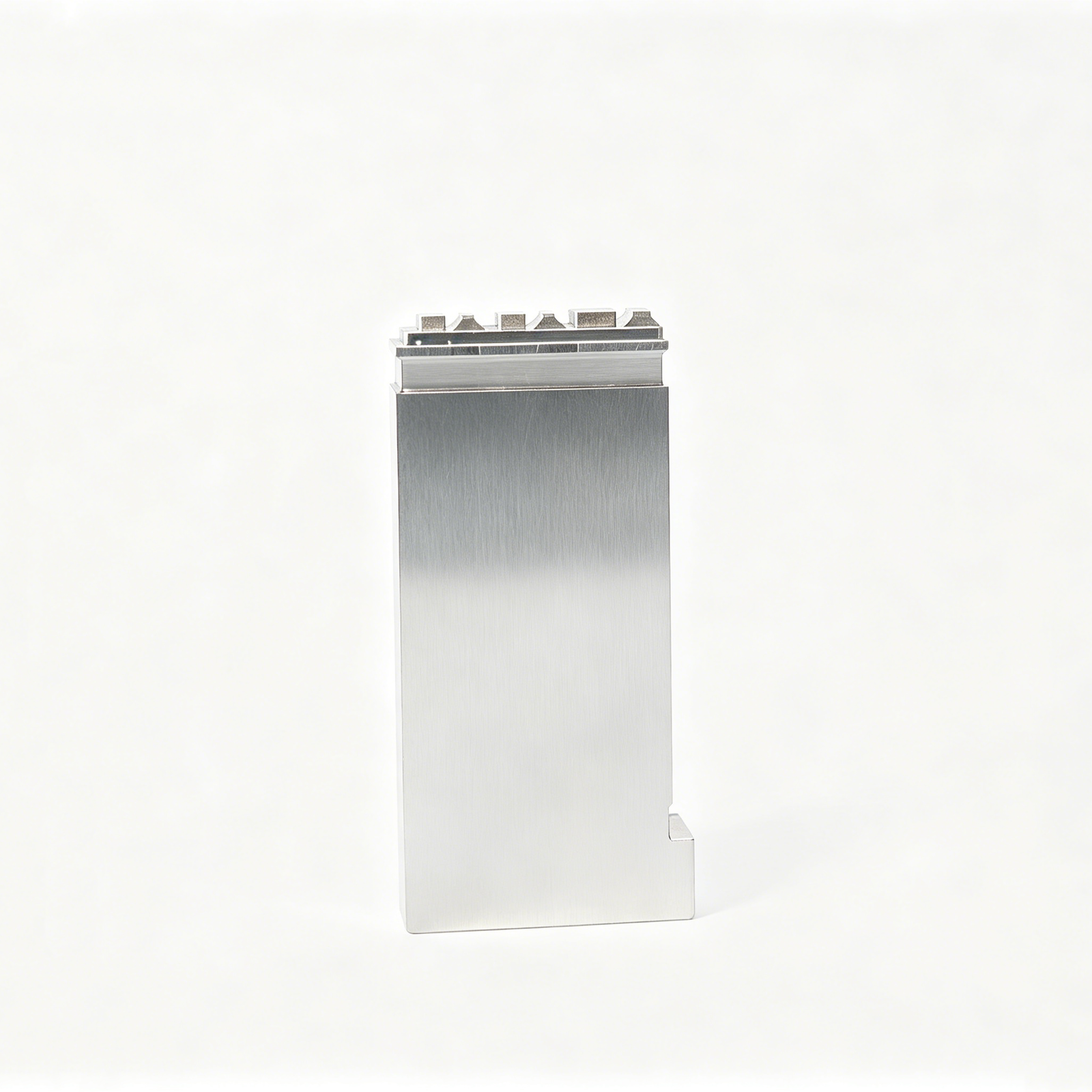
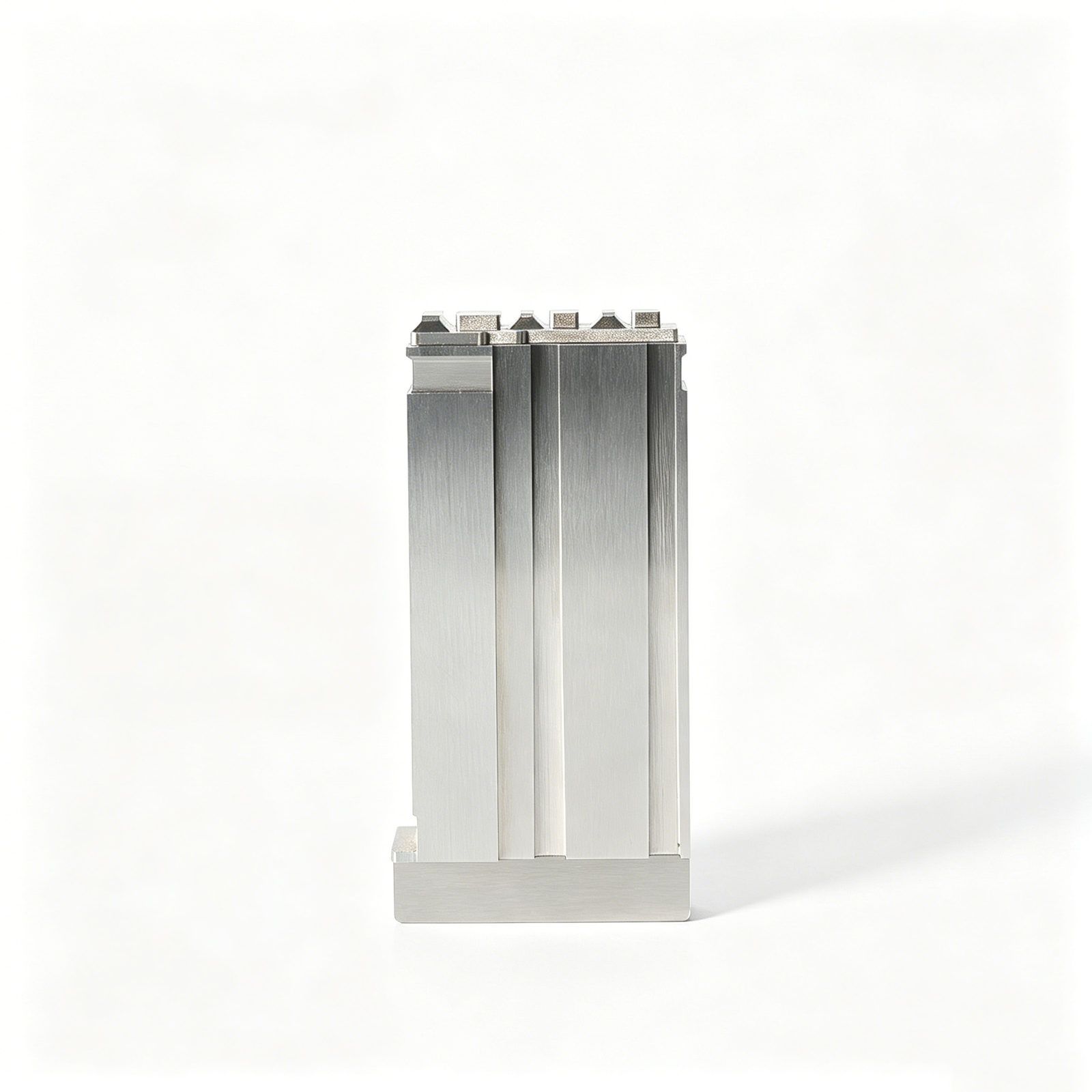
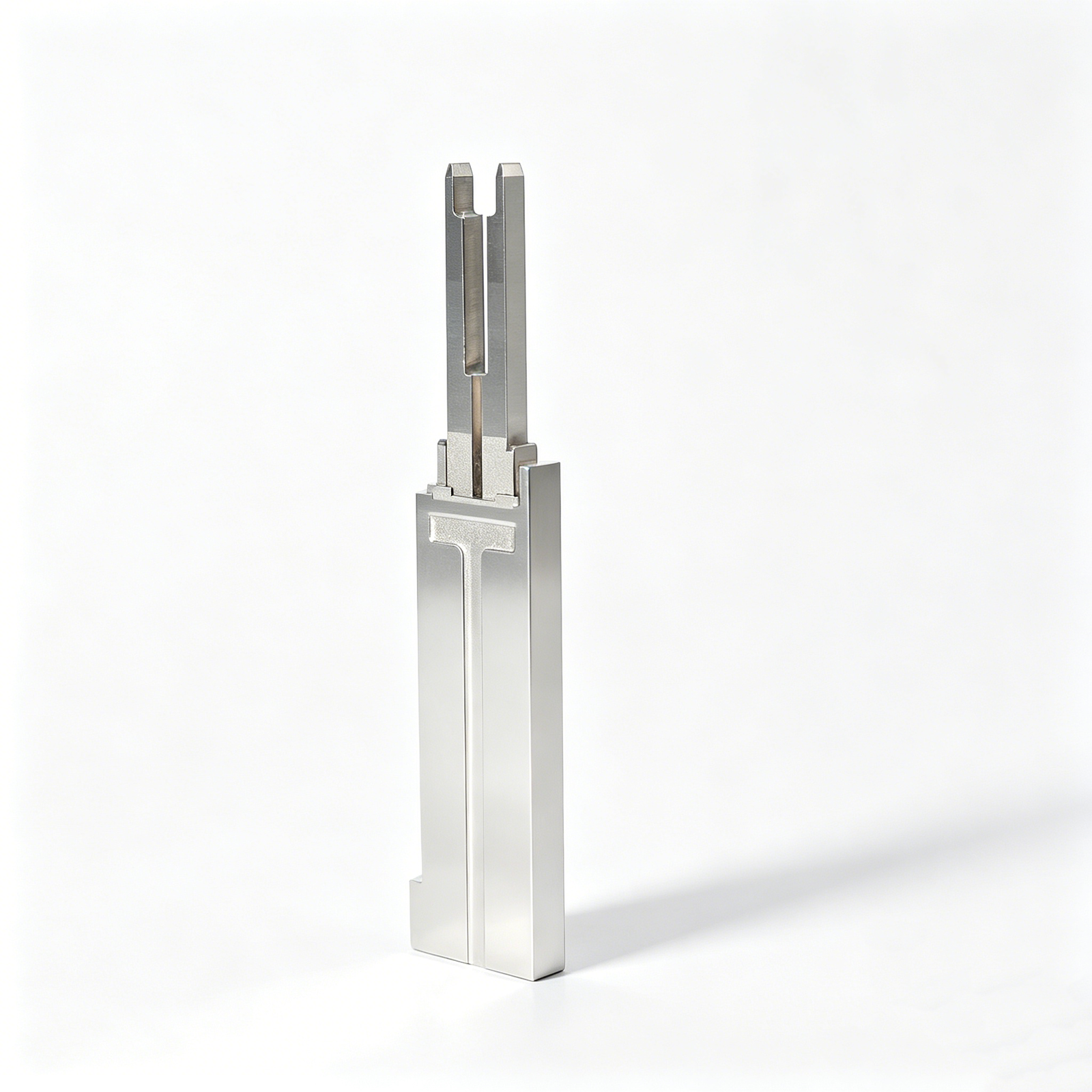
XUXIANG Guide Bush Engineering Advantages
+/-0.001 mm Machining Precision
Micron-stable tolerance on every guide bush, held across slow-wire EDM, CNC grinding and mirror EDM for zero-gap alignment in high-cavity molds.
Ra 0.1 μm Mirror EDM Finish
Mirror-grade surface integrity down to Ra 0.1 μm on guide bush bores and faces, eliminating friction and extending service life in production tooling.
ZEISS MICURA CMM Validation
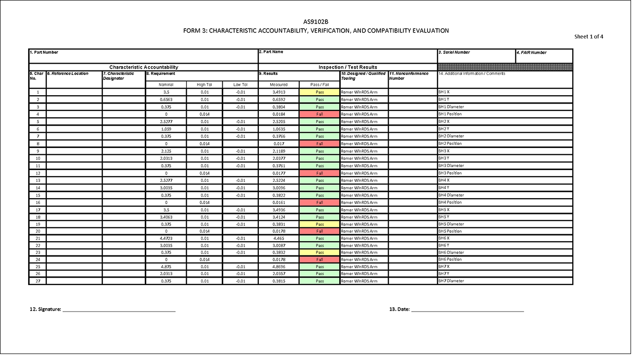
Every guide bush verified on ZEISS MICURA CMM with 0.7 μm resolution, backed by Nikon toolmaker’s microscopes and full FAI documentation with material certificates.
DFM Engineering Support
10+ precision engineers review your guide bush design before machining, flagging tolerance conflicts, interference risks and assembly constraints to eliminate costly revisions.
3–7 Day Rapid Sampling
Sample guide bushes delivered in 3–7 days, mass production in 15–25 days — roughly 30% faster than industry average, with 24-hour quote turnaround.
ISO 9001:2015 Certified Quality
Every guide bush flows through a five-step QC protocol — material spectral analysis, in-process monitoring, CMM verification, surface checks and final FAI — under ISO 9001:2015.
Guide Bush & Mold Component Categories
Precision-ground guide bushes and core components held to +/-0.001 mm, machined on Sodick EDM and Fanuc CNC, validated by ZEISS CMM metrology.
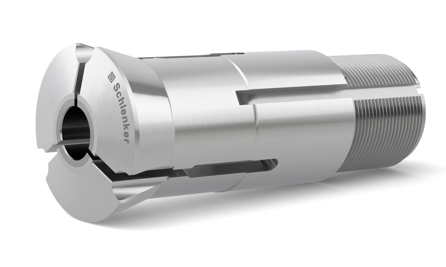
Standard Guide Bushes
Standard guide bushes machined to ISO 9448 and HASCO/DME dimensional standards, held to +/-0.002 mm bore tolerance and Ra 0.4 µm finish. Ground on Dawn precision centers, CMM-verified for straightness and concentricity. Available in SUJ2, SKD61 and SKH51 alloys. Lead time 3–7 days for samples, 15–25 days for production volumes.
Get a Quote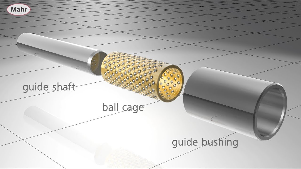
Ball Cage Guide Bushes
Ball cage guide bushes engineered for high-cycle molds requiring low friction and extended tool life. Precision-ground raceways held to +/-0.003 mm, heat-treated to HRC 58–62. Ball retention and cage geometry validated by Nikon toolmaker’s microscope. Suitable for automotive, electronics and high-speed injection tooling with 500,000+ cycle requirements.
Get a Quote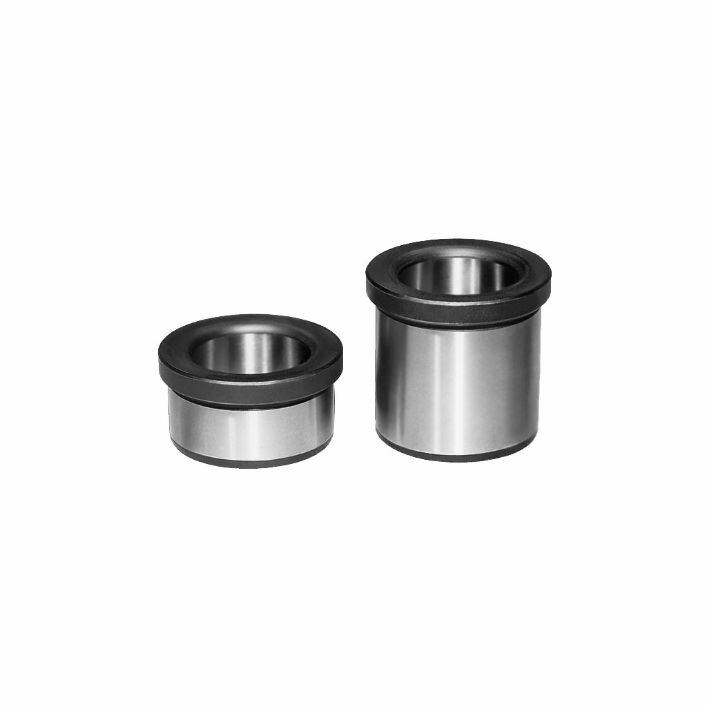
Flanged Guide Bushes
Flanged guide bushes designed for stable shoulder mounting in multi-cavity and family molds. Flange face flatness held to 0.005 mm, bore perpendicularity to +/-0.003 mm, machined on Fanuc CNC and finish-ground. Material options include SKD61, SUJ2 and carbide-tipped variants. DFM review ensures flange thickness matches ejector-plate clearance and clamp load.
Get a Quote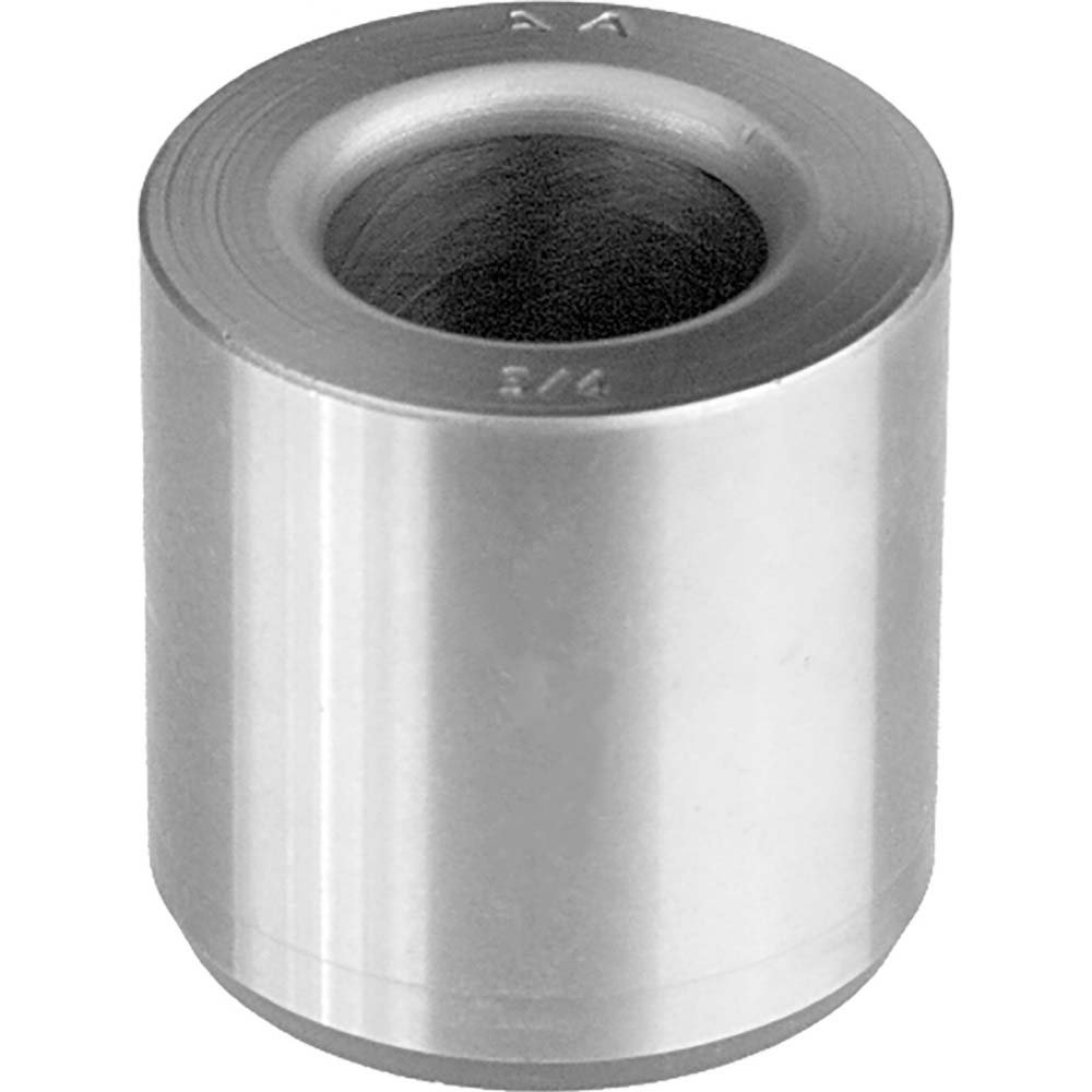
Headless Guide Bushes
Headless guide bushes for tight-clearance applications where top-surface interference must be eliminated. Bore ID held to +/-0.002 mm, chamfer break controlled to 0.1–0.2 mm, length tolerance +/-0.01 mm. Machined from pre-hardened SKD61 or SUJ2, finish-ground and CMM-inspected. Ideal for thin-wall cores, micro-connector tooling and stack molds.
Get a Quote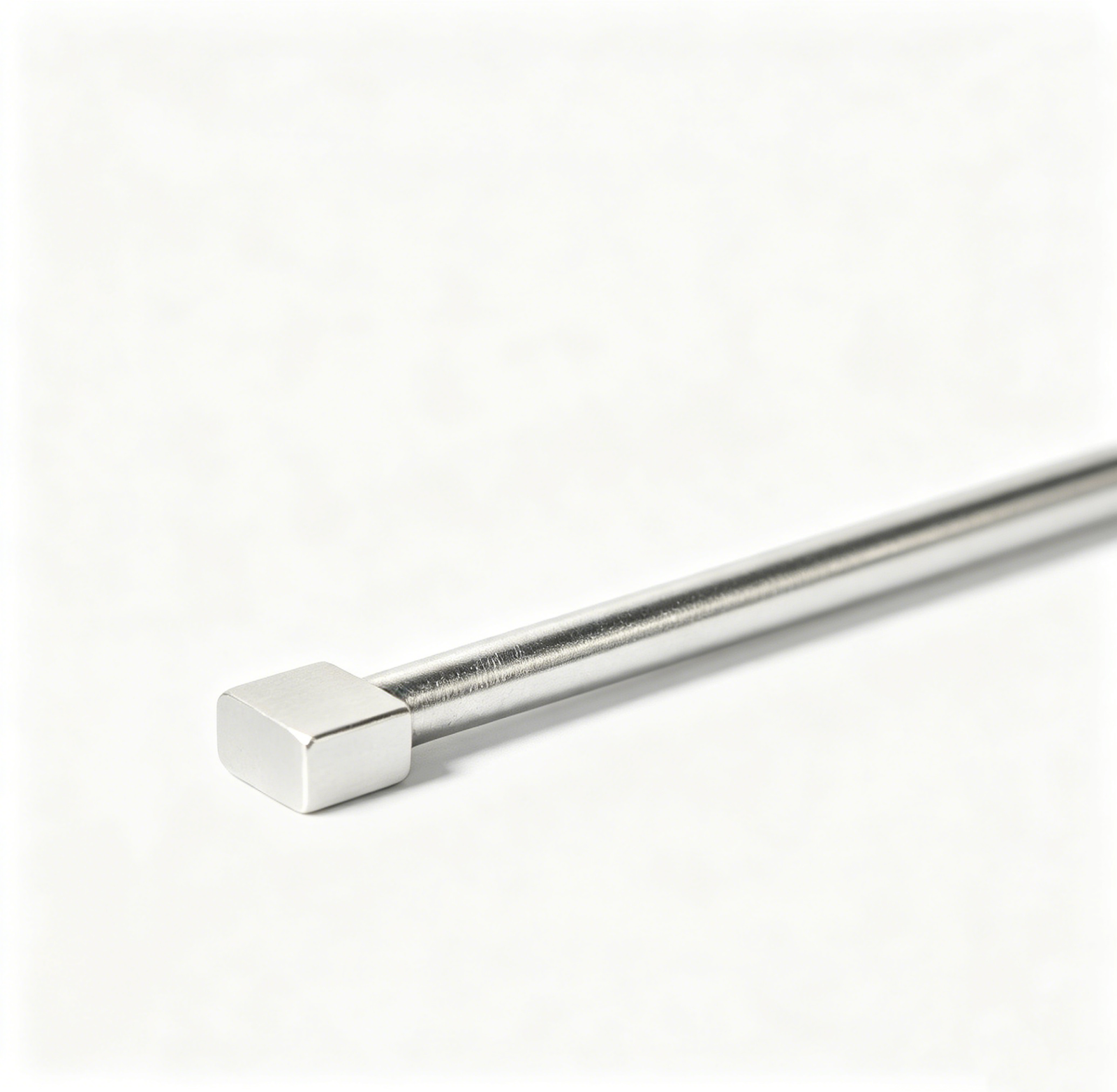
Carbide Guide Bushes
Carbide guide bushes for abrasive-resin molds, glass-filled composites and ultra-high-volume production. YG15 or YG20 tungsten carbide, sintered and cylindrical-ground to Ra 0.2 µm, held to +/-0.002 mm bore and +/-0.005 mm OD. ZEISS MICURA CMM verification of geometry. Wear resistance 10–15× that of tool steel, extending mold maintenance intervals.
Get a Quote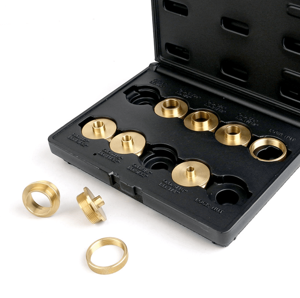
Custom Guide Bushes
Custom guide bushes engineered to non-standard lengths, diameters, flange profiles or material specs. Full DFM collaboration with 10+ mold-design engineers; 3D models reviewed for interference, draft and cooling integration. Machined on Sodick slow-wire EDM and Fanuc CNC, validated with FAI report and material certificates. Quotes returned within 24 hours, samples in 5–7 days.
Get a Quote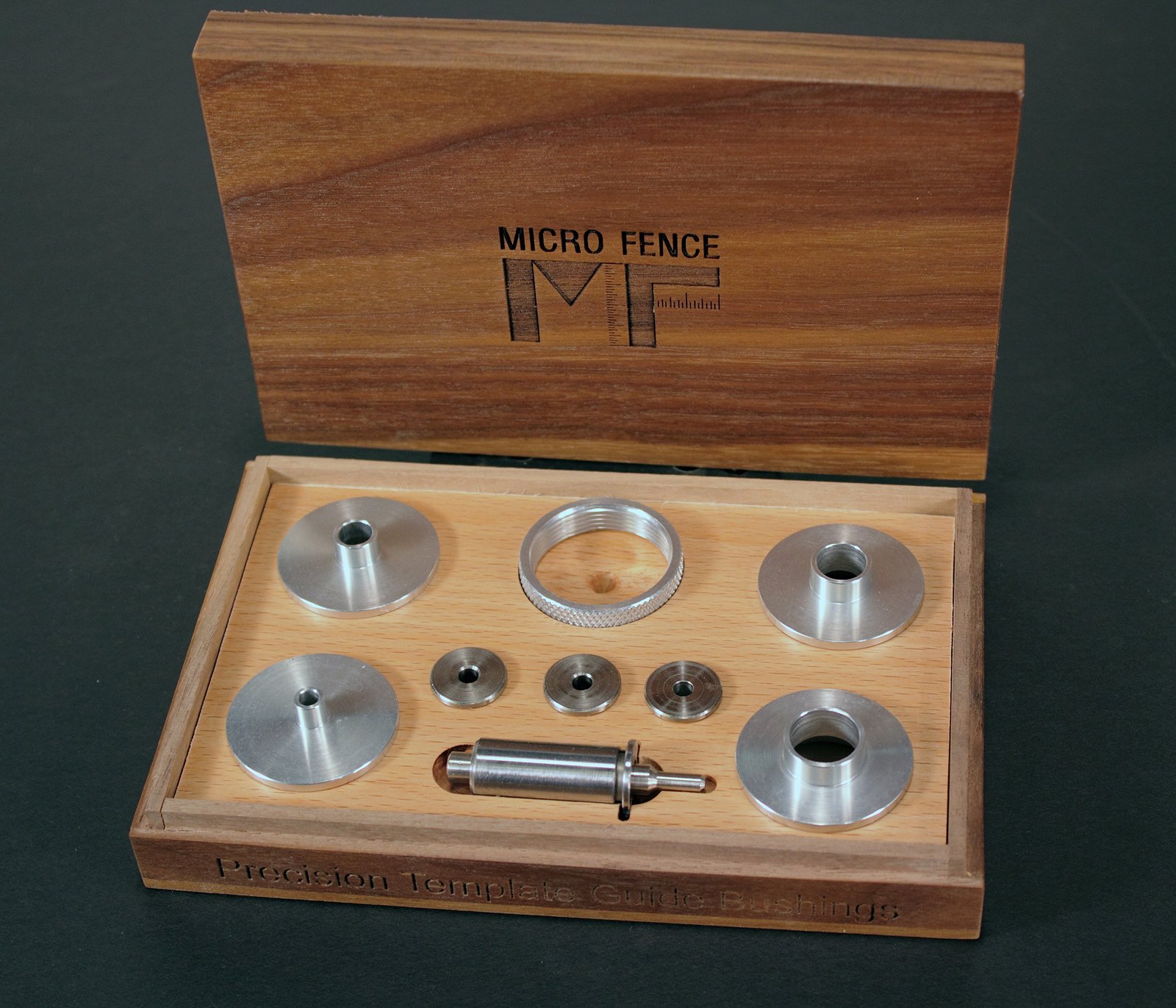
Precision Guide Bush Sets
Precision guide bush sets supplied as matched pairs or full ejector assemblies, ground to cumulative tolerance budgets of +/-0.005 mm across pin/bush interfaces. Sets include alignment verification, serialized marking and protective packaging. Pre-assembly CMM mapping ensures zero misalignment on installation. Designed for zero-draft micro-connector molds, ADAS housings and medical-device tooling.
Get a Quote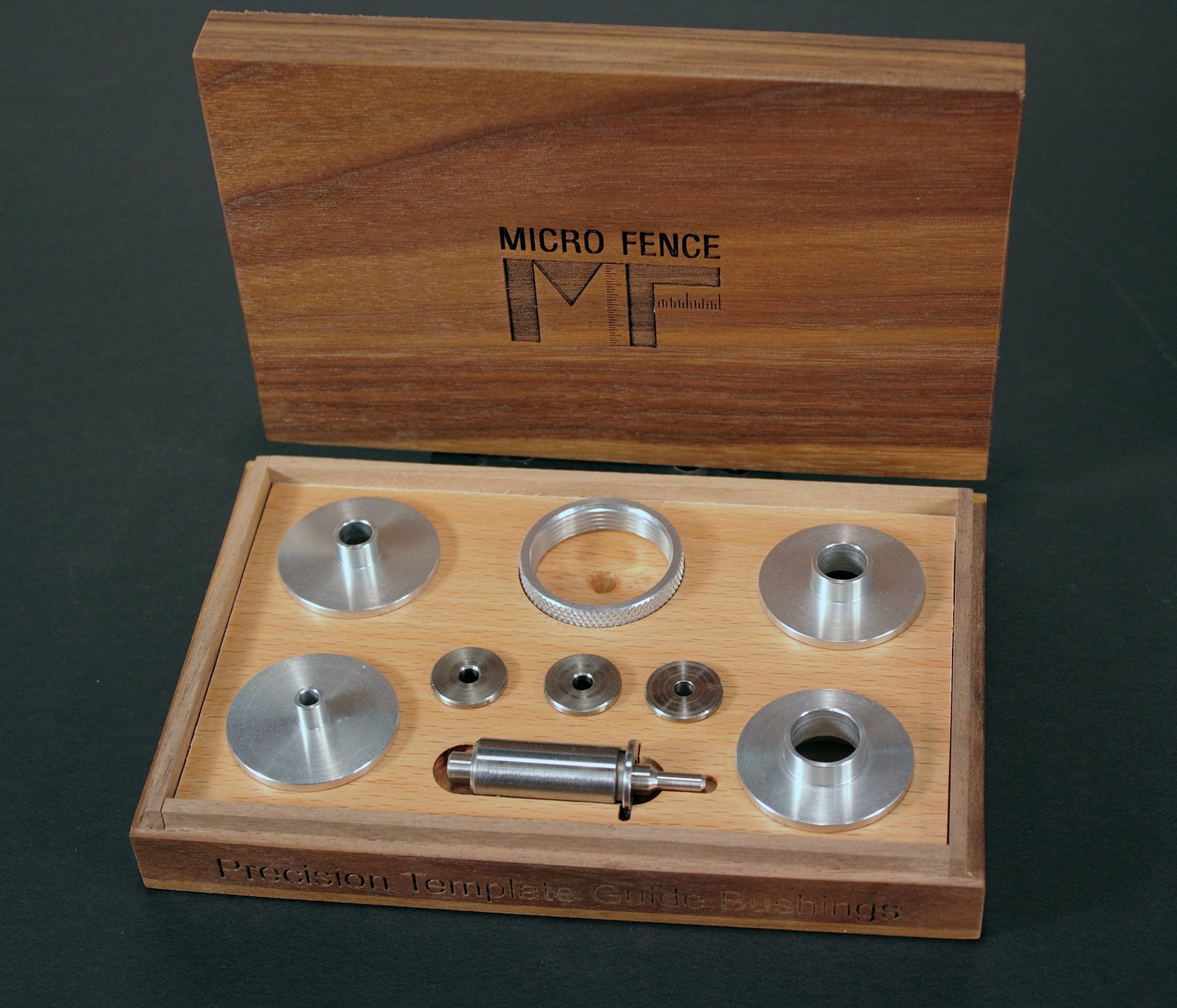
Micro Guide Bushes
Micro guide bushes for pin diameters ≤ 1.0 mm and bore tolerances of +/-0.001 mm, machined on Beijing Jingdiao high-precision CNC and inspected under Nikon V-12B microscope at 200× magnification. Material: SKH51 or carbide. Applications include FPC connector tooling, micro-terminal molds, 5G antenna inserts and board-to-board RF housings requiring sub-millimeter ejector pins.
Get a Quote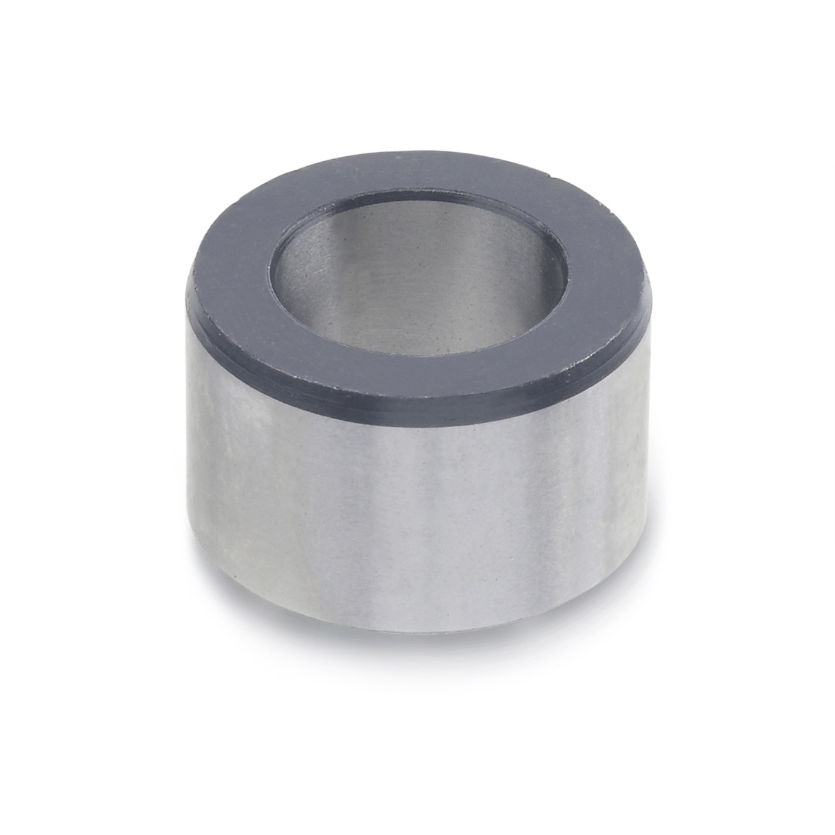
Hardened Guide Bushes
Hardened guide bushes heat-treated to HRC 58–62 for extended wear life in high-volume and abrasive-resin environments. Vacuum-hardened SKD61 or SUJ2, tempered for dimensional stability, then finish-ground to +/-0.002 mm bore and Ra 0.4 µm. Hardness verified by Rockwell tester; geometry validated by ZEISS CMM. Standard in automotive over-molds, glass-filled PA66 and PBT connector housings.
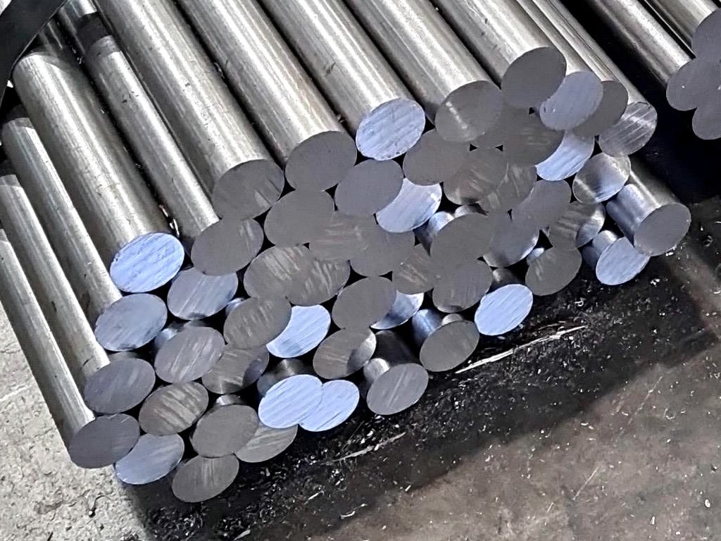
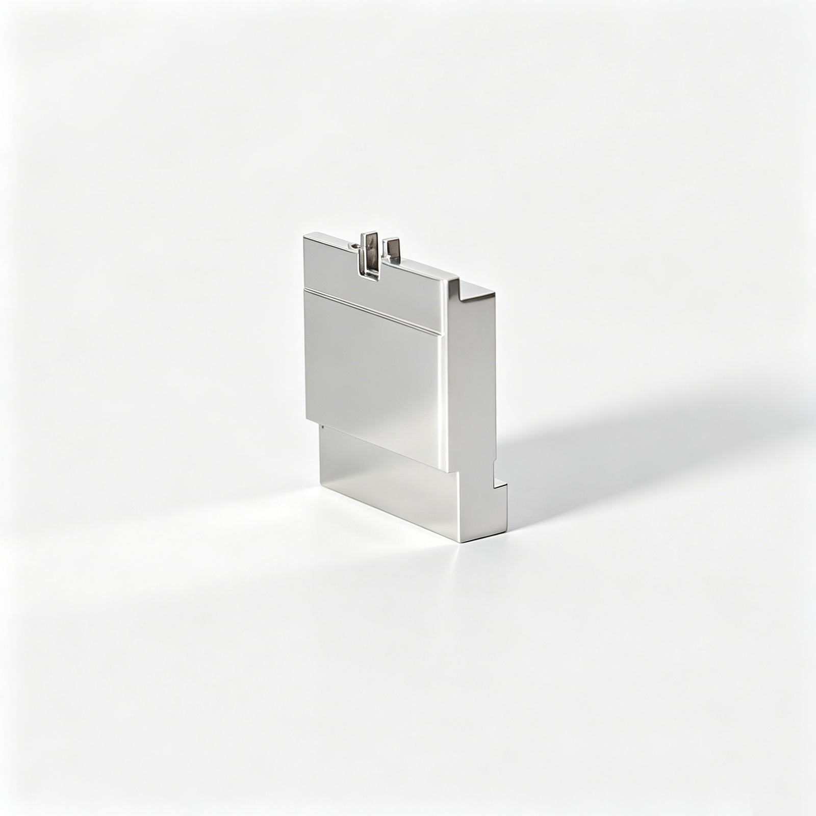
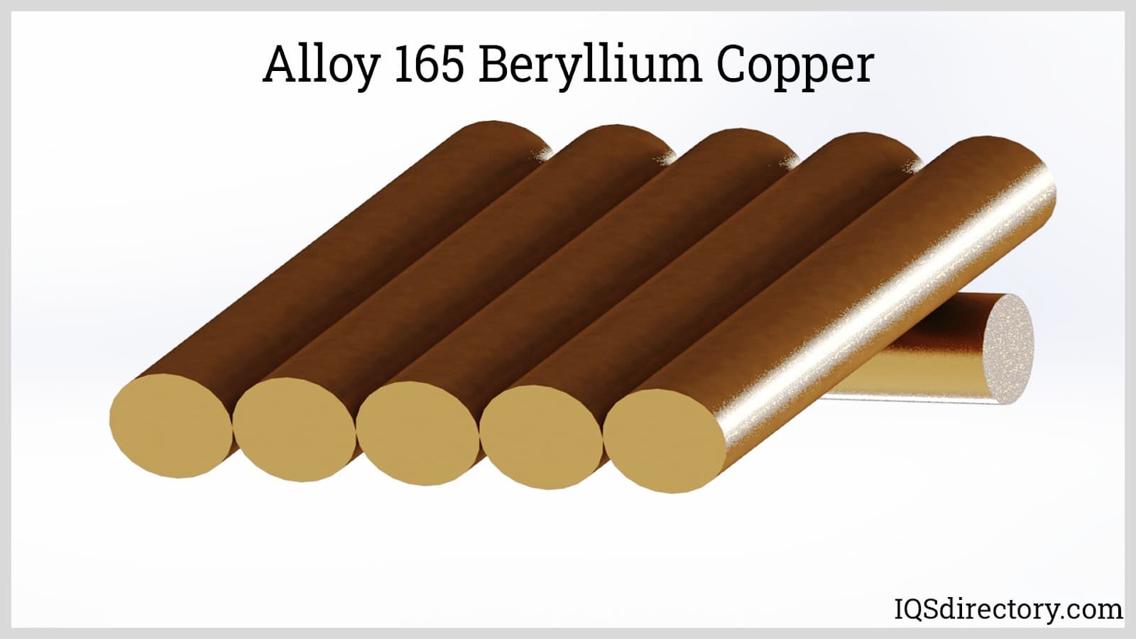
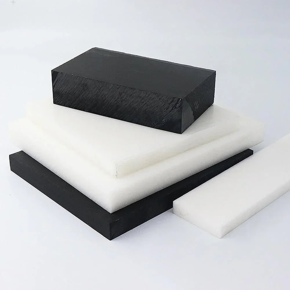
Get a QuoteGuide Bush Materials We Precision-Machine

Precision Machining & Finishing Processes for Guide Bush Components

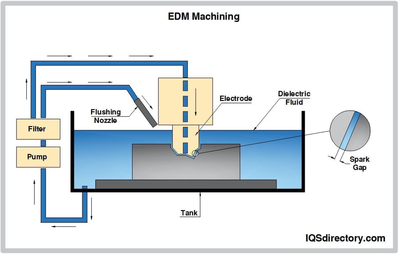
Sinker EDM
Sodick and Charmilles sinker EDM machines produce deep cavities, blind holes and intricate guide bush core details with +/-0.003 mm repeatability, ideal for high-aspect-ratio features and hard-to-machine tool steels.
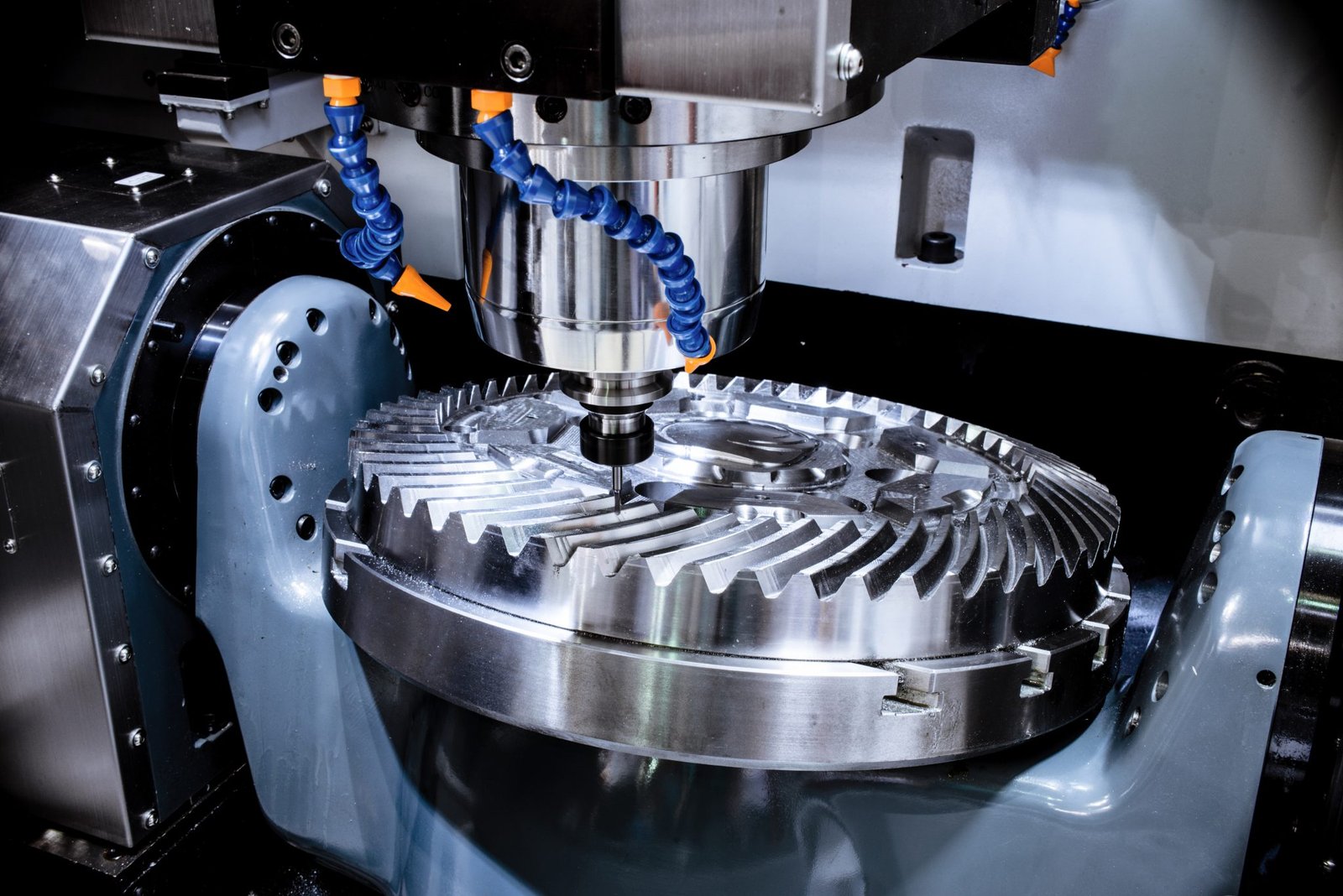
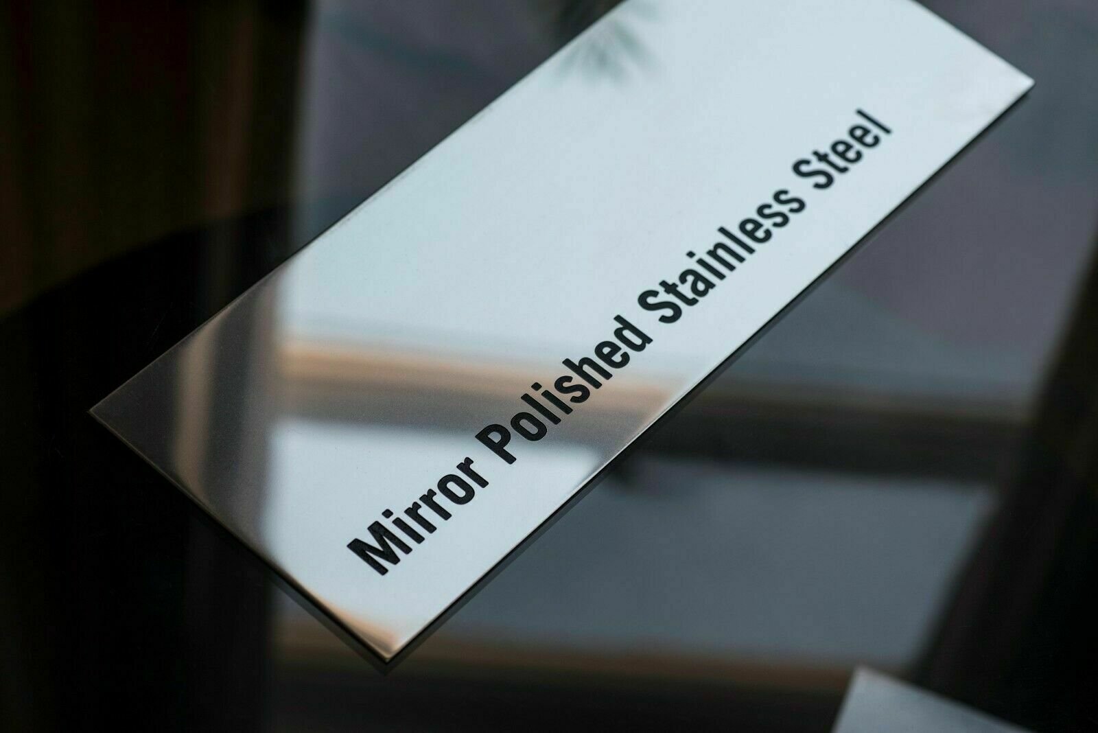
Mirror Finishing
Mitsubishi mirror EDM polishes guide bush surfaces to Ra 0.1 µm finish, eliminating micro-scratches, reducing friction and extending component life in high-speed injection molding and automated assembly environments.
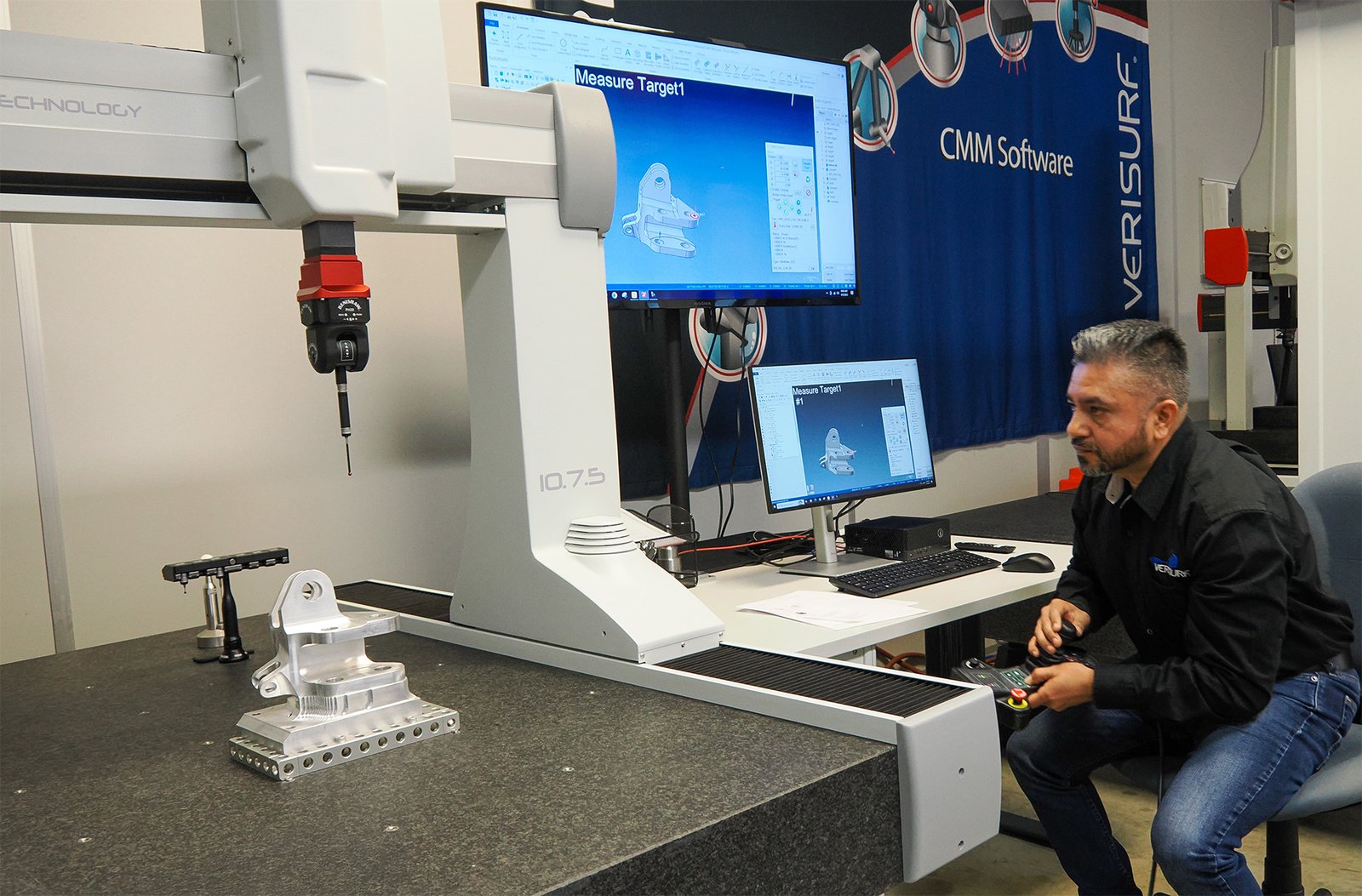
CMM Metrology
ZEISS MICURA coordinate measuring machine validates every guide bush dimension to 0.7 µm resolution, with Nikon toolmaker’s microscopes (V-12B/MM-400) verifying edge quality, surface integrity and geometric tolerances before shipment.
Guide Bush Accessories & Fastening Solutions
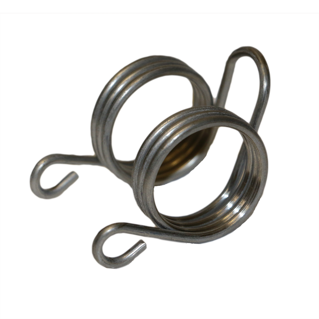
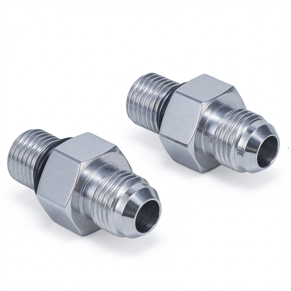
Cooling-Line Fittings
Precision-drilled cooling connectors, quick-disconnect couplings and threaded inserts for conformal cooling circuits adjacent to guide bush zones. Brass, stainless steel or nickel-plated options; leak-tested to 1.0 MPa.
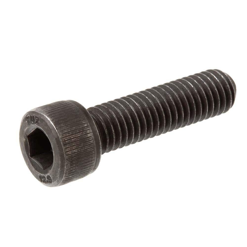
Socket-Head Cap Screws
High-strength alloy-steel socket screws (12.9 grade) for securing guide bushes, wear plates and mold inserts. Available in metric and imperial threads with black-oxide or zinc-plated finishes; torque specifications provided.
About XUXIANG — 16 Years of Precision Mold Innovation
Founded in 2010 in Dongguan’s Chang’an manufacturing hub, XUXIANG has evolved from a specialist mold-core machining shop into a dual-factory precision manufacturing group. Our mission: bridge the gap between complex CAD designs and high-performance physical parts—guide bush components, micro-connector tooling and precision metal hardware—held to +/-0.001 mm and backed by ISO 9001:2015 quality systems.
Today XUXIANG operates 2,000 m² of R&D and micro-machining capacity in Dongguan, plus 1,400 m² of volume production in Quanzhou (launched 2025), delivering +200% expanded capacity. Over CNY 8 million invested in Sodick slow-wire EDM, Mitsubishi mirror EDM, Fanuc CNC and ZEISS MICURA CMM metrology ensures every guide bush, core insert and precision part meets micron-stable tolerances.
What sets us apart: DFM engineering support from 10+ experts, full FAI documentation with material certificates, and lead times 30% faster than industry average. We serve electronics, 5G/telecom, automotive & NEV, industrial automation and medical-device supply chains worldwide—solving tolerance failure and delivery delay with evidence-driven precision and transparent partnership.
Guide Bush Machining to +/-0.001 mm: Four Core Capabilities
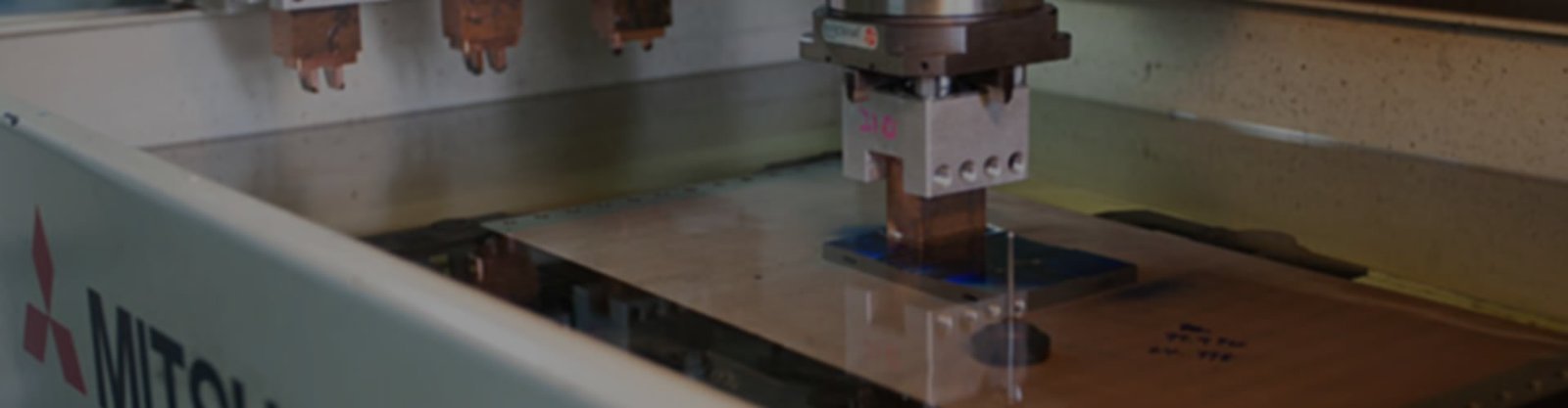
Slow-Wire EDM to +/-0.002 mm
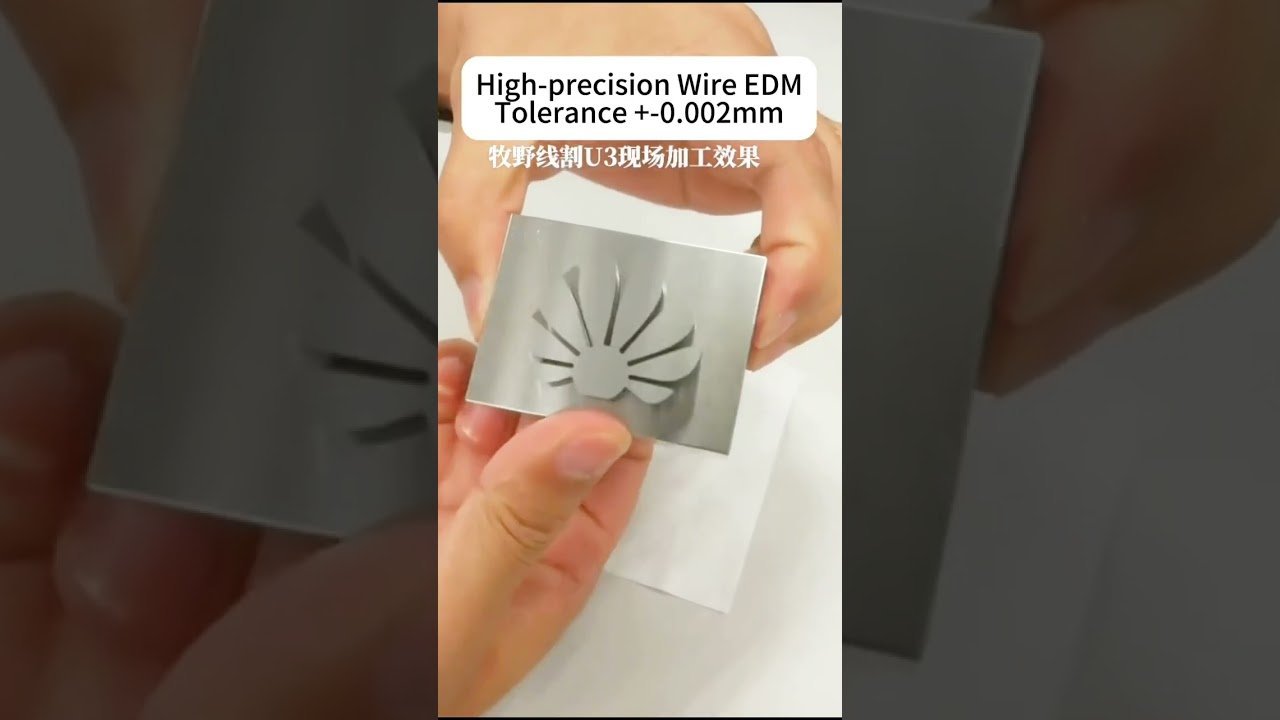
Every guide bush is machined on Sodick and Seibu slow-wire EDM systems to hold +/-0.002 mm positioning accuracy, enabling corner radii down to R ≤ 0.015 mm and complex internal profiles that conventional CNC cannot reach.
- Sodick & Seibu slow-wire EDM for micron-stable repeatability
- Corner radii down to R ≤ 0.015 mm for tight-tolerance mold cavities
- +/-0.002 mm class positioning on multi-axis wire paths
- Complex internal geometries machined without tool-deflection risk
Mirror-Grade Surface Finish Ra 0.1 μm
Mitsubishi mirror EDM and precision grinding deliver Ra 0.1 μm surface finishes on guide bush bore and mating faces, eliminating break-in cycles, reducing friction and extending mold life by up to 40 percent in high-volume production.
- Mitsubishi mirror EDM + Dawn precision grinding to Ra 0.1 μm
- Zero break-in cycles; immediate stable part ejection from first shot
- Low-friction bore surfaces reduce wear on guide pins and ejector pins
- Up to 40% longer mold life in automotive and electronics applications

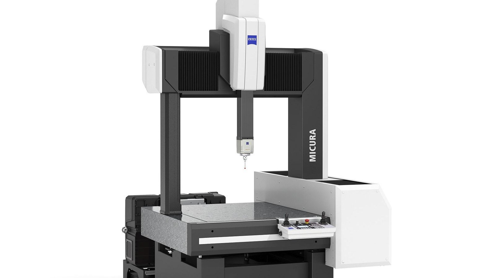
ZEISS CMM Validation to 0.7 μm
Every guide bush undergoes ZEISS MICURA CMM inspection with 0.7 μm resolution, backed by Nikon toolmaker’s microscopes. Full FAI reports, material certificates and dimensional data accompany every shipment, ensuring zero-tolerance surprises at incoming QC.
- ZEISS MICURA CMM with 0.7 μm measurement resolution
- Nikon V-12B / MM-400 class microscopes for surface-integrity checks
- Full FAI reports + material certificates with every order
- Five-step QC flow: spectral analysis, in-process monitoring, CMM, surface check, final FAI
DFM Engineering from 10+ Experts
Before machining begins, your guide bush design is reviewed by a team of 10+ tooling engineers with 16 years of mold-component experience. DFM feedback identifies tolerance risks, material choices and cost-saving geometry changes—preventing costly rework downstream.
- 10+ tooling engineers with 16 years of precision-mold experience
- Pre-production DFM review identifies tolerance risks and material mismatches
- Cost-saving geometry suggestions without compromising function
- Quotes returned within 24 hours with engineering notes attached

XUXIANG Guide Bush vs. Standard Mold Component Suppliers
Evidence-based precision: real equipment, verified tolerances and documented quality — not marketing claims.
← 左右滑动查看 →
How We Manufacture Every Guide Bush
Six quality-controlled phases ensure every guide bush and precision mold component meets +/-0.001 mm tolerance, backed by ZEISS metrology and full FAI documentation.
DFM Review & Material Selection
10+ engineering experts analyze your CAD file for manufacturability, then specify certified steel, carbide or bronze stock with full material traceability and spectral verification.
CNC & EDM Machining
Sodick slow-wire EDM, Fanuc CNC and Beijing Jingdiao high-precision centers machine guide bush blanks to +/-0.001 mm, holding corner radii down to R ≤ 0.015 mm.
In-Process Tolerance Monitoring
Operators measure critical dimensions at every setup change using Nikon toolmaker’s microscopes and gauge blocks, catching drift before it becomes scrap.
ZEISS & Nikon CMM Verification
Every guide bush batch undergoes coordinate-measuring-machine inspection on our ZEISS MICURA (0.7 µm resolution) and Nikon V-12B / MM-400 class microscopes for final dimensional validation.
Surface Integrity & FAI Documentation
Ra 0.1 µm mirror-finish checks, hardness testing and first-article inspection reports are compiled with material certificates, ready for your incoming QC team.
Precision Packing & Expedited Shipping
Parts are cleaned, individually wrapped in anti-corrosion film and packed in foam-lined cartons, then shipped via your preferred carrier with full traceability.
How to Partner With XUXIANG for Guide Bush & Mold Components
Evidence-based precision: named equipment, verified tolerances and documented quality systems — not marketing claims.
Submit Your CAD & Technical Requirements
Upload 2D/3D drawings, material specs and tolerance callouts. Our engineering team reviews every file for manufacturability and identifies potential design optimizations before quoting.
Receive DFM Feedback & 24-Hour Quote
Within 24 hours, you’ll receive a detailed quote plus DFM recommendations from 10+ precision-mold experts to improve tooling life, reduce cycle time and ensure dimensional stability.
Approve Sample & Validate Tolerances
We machine a first-article sample, inspect it on our ZEISS MICURA CMM and ship it with a full dimensional report. Sample lead time is typically 3–7 days.
Launch Bulk Production With FAI
After sample approval, mass production begins under ISO 9001:2015 controls. Every shipment includes FAI documentation, material certificates and CMM validation reports for full traceability.
ISO 9001:2015 & Industry Certifications for Guide Bush Precision




Guide Bush Customer Testimonials & Case Studies
XUXIANG delivered 240 guide bushes for our connector mold project with +/-0.002 mm tolerance verified on every piece. Lead time was 18 days — 30% faster than our previous supplier. We’ve placed three repeat orders since.
We needed mirror-finish guide bushes for a 16-cavity automotive sensor housing mold. XUXIANG hit Ra 0.12 µm and held positional tolerance within +/-0.0015 mm across all cavities. The FAI report was the most detailed we’ve received.
After two failed attempts with other shops, XUXIANG machined our medical-grade guide bush inserts to +/-0.001 mm and provided full material certificates. Their DFM feedback caught a critical interference issue before production. Saved us at least four weeks.
FAQ: Guide Bush Sourcing & Mold Component Lead Times
What is the minimum order quantity (MOQ) for guide bush components?
How long does it take to receive guide bush samples versus production orders?
Do you charge for guide bush samples, and is the cost refundable?
What tolerances can you guarantee on precision guide bushes?
Which materials do you machine for guide bush applications?
What payment terms do you offer for new customers?
How do you protect intellectual property and design confidentiality?
What shipping options are available, and do you handle international logistics?
Can you provide design-for-manufacturing (DFM) feedback before I commit to an order?
The Complete Buyer’s Guide to Guide Bush Precision Mold Components
Navigate the critical specifications, material grades, and tolerance requirements for guide bush selection. This guide delivers a proven decision framework, supplier evaluation criteria, and the most common procurement mistakes to avoid when sourcing precision mold components.
1. What Is a Guide Bush and Why Precision Matters
A guide bush is a hardened steel sleeve inserted into a mold plate to guide ejector pins, core pins, or slides with micron-level concentricity, typically machined to +/-0.001 mm bore tolerance and held to +/-0.002 mm positional accuracy. In high-cavitation injection molds — especially 16-cavity, 32-cavity, or 64-cavity arrays — guide bushes prevent lateral deflection during ejection cycles, ensuring each pin travels perpendicular to the parting line and strikes the molded part at the same location every cycle.
Without precision guide bushes, ejector pins deflect under side loads, causing witness marks, core shifts, or ejector-pin breakage in thin-wall parts. Electronics housings with 0.3 mm wall sections, micro-connector tooling with pin-to-pin pitch below 0.5 mm, and automotive sensor housings demand +/-0.001 mm bore roundness to maintain alignment over millions of cycles.
XUXIANG machines guide bush bores on Sodick and Seibu slow-wire EDM to +/-0.002 mm class positioning, verified on a ZEISS MICURA CMM measuring to 0.7 µm resolution, ensuring repeatable part quality across high-volume production runs.
2. Evolution of Guide Bush Manufacturing Standards
Before 1990, guide bush manufacturing relied on manual grinding of hardened steel sleeves, with typical tolerances of +/-0.02 mm sufficient for consumer-goods molds. The introduction of CNC Swiss-type lathes in the late 1990s enabled repeatable sub-0.01 mm accuracy, while ISO 8062 dimensional standards (originally cast-metal focused) became the reference framework for mold-component tolerancing by the early 2000s.
The 5G connector boom after 2015 redefined guide bush requirements entirely. Board-to-board and FPC interconnects demanded pin-to-socket clearances below 0.05 mm, pushing tolerance bands to +/-0.002 mm and tighter. XUXIANG’s investment in Sodick slow-wire EDM and ZEISS MICURA CMM (0.7 µm resolution) reflects this shift: modern guide bush now routinely achieves +/-0.001 mm positional accuracy and Ra 0.1 µm mirror finishes.
Today’s precision guide bush incorporates surface treatments — nitriding, DLC coatings, PVD — that extend service life in micro-connector tooling by 300–500% versus uncoated sleeves, meeting the cycle-count and wear-resistance demands of high-volume NEV and telecom production.
3. Types of Guide Bush for Mold Applications
Guide bush architecture varies by load path, mounting method and wear environment. Selecting the correct type ensures alignment stability, minimizes downtime and optimizes tool life across electronics, automotive and connector mold platforms.
Straight Guide Bushings

Straight bushings feature uniform OD along the entire length, press-fitted into guide plates per ISO 8405 or MISUMI dimensional standards. Typical diameters range 3–50 mm with +0.005/0 mm hole tolerance.
Used in general-purpose injection molds where plate thickness allows full-length press retention. XUXIANG machines straight bushings to +/-0.002 mm on OD and ID for consistent pin clearance.
Flanged Guide Bushings

Flanged designs add a machined shoulder that seats against the plate face, simplifying installation and preventing axial migration under ejector shock. Flange thickness typically 3–6 mm, OD 1.5–2× bushing body.
Specified for high-cycle automotive and connector molds where rapid changeout is critical. Flanged bushings reduce assembly time by approximately 40% versus straight press-fit types.
Ball-Bearing and Self-Lubricating Types

Ball-bearing guide bushings incorporate precision steel balls in raceways, suited to high-speed or oscillating mold actions above 120 cycles/hour. Self-lubricating bronze-lined bushings embed oil-impregnated sintered bronze, eliminating external lubrication in clean-room or sealed environments.
XUXIANG validates bearing-type bushings on ZEISS CMM to ensure raceway concentricity within 0.003 mm, critical for micro-connector tooling and medical-device molds.
4. Guide Bush Materials and Performance Characteristics
Material selection determines guide bush service life, dimensional stability and total cost of ownership. Five primary alloys dominate precision tooling applications, each optimized for specific load, environment and cycle-volume profiles.
| Material | Hardness (HRC) | Wear Life (cycles) | Corrosion Resistance | Typical Cost Index | Best-Fit Application |
|---|---|---|---|---|---|
| SUJ2 Bearing Steel | 58–64 | 1–3 million | Low | 1.0× | High-volume standard molds, dry environments |
| SKH51 High-Speed Tool Steel | 62–66 | 3–5 million | Moderate | 1.8× | Abrasive resins, elevated temperatures |
| Tungsten Carbide | 88–92 | 10+ million | Excellent | 5.0× | Ultra-high-cycle micro-connector tooling |
| Bronze Alloy (C95400) | 85–95 (HB) | 500k–1M | Excellent | 2.2× | Corrosive coolants, low-friction sliding |
| SUS440C Stainless | 56–60 | 1.5–2.5 million | Excellent | 1.5× | Medical/food-grade molds, humid plants |
5. Surface Treatments and Coating Options for Guide Bush
Surface treatments extend guide bush service life by reducing friction, raising surface hardness and protecting against wear in high-cycle mold operations. Selection depends on shot count, material abrasiveness and budget: a 500,000-shot consumer-electronics mold may run untreated SKH51, while a 10M+ micro-connector tool demands DLC or plasma nitriding.
| Treatment | Hardness (HV) | Friction Coeff. | Relative Cost |
|---|---|---|---|
| Gas nitriding | 700–1,000 | 0.3–0.4 | 1.0× |
| Plasma nitriding | 700–1,000 | 0.3–0.4 | 1.2× |
| TiN (PVD) | ~2,300 | 0.5–0.6 | 1.5× |
| TiAlN (PVD) | ~3,000 | 0.4–0.5 | 1.7× |
| CrN (PVD) | ~1,800 | ~0.4 | 1.6× |
| DLC | 2,000–4,000 | ~0.1 | 3.0× |
| Electroless Ni | 500–700 | 0.5–0.6 | 0.8× |
Nitriding: Gas vs. Plasma
Gas nitriding diffuses nitrogen into steel at 500–550°C, achieving 700–1,000 HV case hardness and a 0.1–0.3 mm deep case; cycle time is 20–60 hours. Plasma (ion) nitriding operates at 350–500°C with faster cycles (8–24 hours), tighter dimensional control (+/-0.005 mm typical) and selective masking for threads.
Both cut friction coefficient by ~30% and suit high-volume automotive and 5G connector tooling where guide bush stroke exceeds 1 million cycles.
PVD Coatings: TiN, TiAlN and CrN
Physical vapor deposition applies 1–5 µm ceramic films at 200–500°C, preserving tight tolerances. TiN (gold, 2,300 HV) is entry-level; TiAlN (violet-gray, 3,000 HV) adds oxidation resistance to 800°C for hot-runner bushings; CrN (silver, 1,800 HV) offers lowest friction (µ ≈ 0.4) for micro-pin ejector guides.
PVD adds 15–25% to component cost but doubles service life in abrasive glass-filled resins.
DLC and Electroless Nickel
Diamond-like carbon delivers ultra-low friction (µ ≈ 0.1), 2,000–4,000 HV hardness and biocompatibility for medical-device molds requiring 10M+ shots and no particle shedding. Film thickness is 0.5–3 µm; cost is 2–3× PVD.
Electroless nickel plating (5–25 µm, 500–700 HV) provides uniform coverage on complex geometries and corrosion resistance for humid or marine environments, at roughly half the cost of PVD.
6. Critical Quality Elements in Precision Guide Bush
Six measurable checkpoints separate precision guide bush from commodity hardware. Each parameter directly affects mold alignment, cycle life and part repeatability, and each demands calibrated metrology to verify compliance with ISO 286-2 H7/g6 fit classes.
Dimensional Tolerance: OD, ID and Length
Outer diameter, inner diameter and overall length must hold +/-0.002 mm or tighter for multi-cavity tooling. CMM verification on ZEISS-class systems confirms conformance; air gauging offers faster in-process checks for bore diameter. ISO 286-2 H7 bores and g6 shafts define the clearance envelope for sliding fits.
Concentricity, Perpendicularity and Bore Straightness
Concentricity between OD and ID should not exceed 0.003 mm total indicator reading; perpendicularity of flange face to bore axis must stay within 0.005 mm over the full length. Optical comparators and rotary-table CMM routines measure these geometric tolerances. Internal bore straightness under 0.002 mm per 100 mm prevents binding and premature wear.
Surface Finish, Hardness and Flange Flatness
Mirror-grade bores at Ra ≤ 0.2 μm reduce friction and particle generation. Hardness uniformity across HRC 58–62 ensures consistent wear resistance; Rockwell testing at three zones verifies heat-treat quality. Flange flatness within 0.003 mm, measured by granite surface plate and dial indicator, guarantees clamping stability and prevents deflection under press loads.
7. How to Choose a Guide Bush Manufacturer
Selecting a guide bush supplier demands a methodical scorecard that balances machining capability, process control and delivery performance. The right partner combines precision equipment with transparent quality systems and scalable capacity.
Machining and Heat-Treatment Infrastructure
Verify that the shop operates Swiss-type CNC lathes or 5-axis grinding centers capable of holding +/-0.002 mm on diameter and concentricity. In-house heat treatment and coating (nitriding, PVD) eliminate third-party delays and traceability gaps.
XUXIANG runs Sodick slow-wire EDM and Dawn precision grinders, achieving +/-0.001 mm machining accuracy and mirror finishes to Ra 0.1 µm, with full heat-treatment coordination through certified partners.
Inspection and Process Control
Ask whether CMM inspection is performed on every batch and if SPC charts track critical dimensions in real time. A ZEISS or Mitutoyo CMM with sub-micron resolution is the industry benchmark.
XUXIANG’s ZEISS MICURA measures to 0.7 µm and Nikon toolmaker’s microscopes validate surface integrity, backed by five-step QC and full FAI documentation with material certificates under ISO 9001:2015.
Lead Time, MOQ and Certifications
Prototype runs should ship within 7–10 days; production batches in 15–20 days. Confirm minimum order quantities align with your forecast — flexible suppliers accept 50–100 pcs for trials.
ISO 9001 is baseline; IATF 16949 certification is essential for automotive tier suppliers. XUXIANG delivers approximately 30% faster than industry average and scales from prototype to mass production with transparent, fair pricing.
8. Common Mistakes When Sourcing Guide Bush Components
Procurement errors in guide bush sourcing cascade into mold downtime, scrap and costly rework. Five mistakes account for the majority of field failures: vague tolerances, missing heat-treat documentation, reliance on visual checks, skipped fit analysis and underestimated lead times for custom geometries.
Specifying Generic Tolerances Instead of H7/g6 Fits
Requesting ‘+/-0.05 mm’ or ‘tight’ tolerances leaves the supplier to interpret clearance, often resulting in interference or excessive play. Pin galling and premature wear follow.
Call out ISO H7/g6 or equivalent hole-shaft fits explicitly. XUXIANG’s CMM validates fit to +/-0.001 mm, eliminating guesswork and ensuring smooth ejector-pin travel across millions of cycles.
Ignoring Heat-Treatment Certification
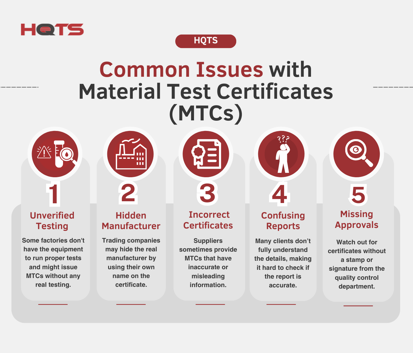
Accepting guide bush without hardness reports risks soft bores that wear within weeks. Mold rework to replace bushings can exceed $2,000 per cavity.
Demand material certificates and post-quench hardness data (typically HRC 58–62 for tool steel). XUXIANG supplies spectral analysis and hardness test reports with every shipment, traceable to batch records.
Accepting Visual Inspection Instead of CMM Reports
Visual checks miss sub-micron bore taper and out-of-round conditions that cause stick-slip. Production downtime for troubleshooting averages 4–8 hours per incident.
Require ZEISS or equivalent CMM dimensional reports. XUXIANG’s 0.7 µm ZEISS MICURA validates bore straightness, concentricity and length, documented in the final FAI package.
9. Guide Bush Pricing and Cost Structure
Guide bush pricing follows five distinct volume tiers, with unit costs declining 40–60% from prototype to series production. Material grade — SKD11, SKH51, tungsten carbide — typically accounts for 25–35% of the total part cost, while surface treatment (nitriding, PVD coating, mirror polishing to Ra 0.1 µm) adds 15–30% depending on specification.
Custom dimensions and tight tolerance bands drive setup costs: standard catalog sizes incur no tooling charge, whereas bespoke diameters, lengths or +/-0.001 mm tolerances may require CNY 500–2,000 in grinding-wheel dressing and CMM programming. Full ZEISS CMM inspection reports with material certificates add approximately USD 8–15 per part on small batches but are absorbed into unit price above 200 pieces.
Volume break-even occurs between 50 and 200 pieces for most guide bush families; buyers ordering 500+ units per year should negotiate blanket purchase orders with quarterly releases to lock pricing and secure 20–25% faster lead times. XUXIANG offers transparent, itemized quotations within 24 hours, separating material, machining, treatment and inspection costs for full procurement visibility.
| Quantity Tier | Unit Price (USD) | Lead Time (Days) | Tooling/Setup Cost |
|---|---|---|---|
| 1–10 pcs | $18–45 | 7–10 | Custom: $70–280 |
| 11–50 pcs | $12–32 | 10–14 | Custom: $70–280 |
| 51–200 pcs | $8–22 | 12–18 | Amortized or waived |
| 201–500 pcs | $6–16 | 15–21 | Waived |
| 500+ pcs | $4–12 | 18–25 | Waived; blanket PO discounts apply |
10. Steps to Launch Your Precision Mold Project with Guide Bush
A structured procurement roadmap reduces lead time by 20–30% and eliminates tolerance rework. The six-step sequence below clarifies handoff points between design, tooling, and procurement teams, ensuring every guide bush meets dimensional and material requirements before production.
Define Mold Layout and Pin Clearances
CAD review identifies guide-pin diameter, slide stroke, and required clearance — typically 0.005–0.010 mm for standard bushings, +/-0.002 mm for high-precision applications. DFM feedback from XUXIANG’s engineering team confirms bush position, length, and interference-fit tolerance before material selection.
Specify Type, Material, and Tolerances
Document bush style (straight, flanged, or ball-cage), base material (SUJ2, SKD61, or bronze), and surface treatment (nitriding, TiN coating). Include bore-diameter tolerance (+/-0.001 mm for XUXIANG standard), surface finish (Ra ≤ 0.2 µm), and hardness range (58–62 HRC for steel variants).
Request Samples and CMM Reports
First-article samples ship with ZEISS MICURA CMM data (0.7 µm resolution), material certificates, and hardness test results. Typical sample lead time is 5–7 days; production lots follow within 10–15 days after approval, contingent on order volume.
Validate Fit in Prototype Mold
Install sample bushings in prototype tooling to verify pin clearance, slide alignment, and thermal expansion behavior under injection cycles. Record any wear or galling after 500–1,000 shots; adjust tolerances or coatings if needed before issuing production PO.
Issue Production PO with Inspection Criteria
Purchase orders specify CMM verification points, acceptable bore-diameter range, surface-finish limits, and packaging requirements. XUXIANG’s five-step QC flow — spectral analysis, in-process monitoring, CMM verification, surface checks, and FAI documentation — ensures batch-to-batch consistency.
Establish Inventory and Reorder Triggers
Set minimum stock levels based on mold shot count and bush wear life (typically 50,000–200,000 cycles). Automate reorder triggers at 30% remaining inventory to avoid line downtime; XUXIANG’s 30% faster delivery supports just-in-time replenishment without safety-stock bloat.
Ready to Source Your Guide Bush & Mold Components?
Get a quote in 24 hours with full DFM support, ZEISS-verified tolerances, and delivery 30% faster than industry average.