
Electronic Components Mold — Micron-Stable Precision Tooling for 5G, Automotive & Medical
ISO 9001:2015 electronic components mold machined to +/-0.001 mm with ZEISS CMM validation, Sodick EDM and 24-hour quotes — trusted by OEM/ODM buyers worldwide.
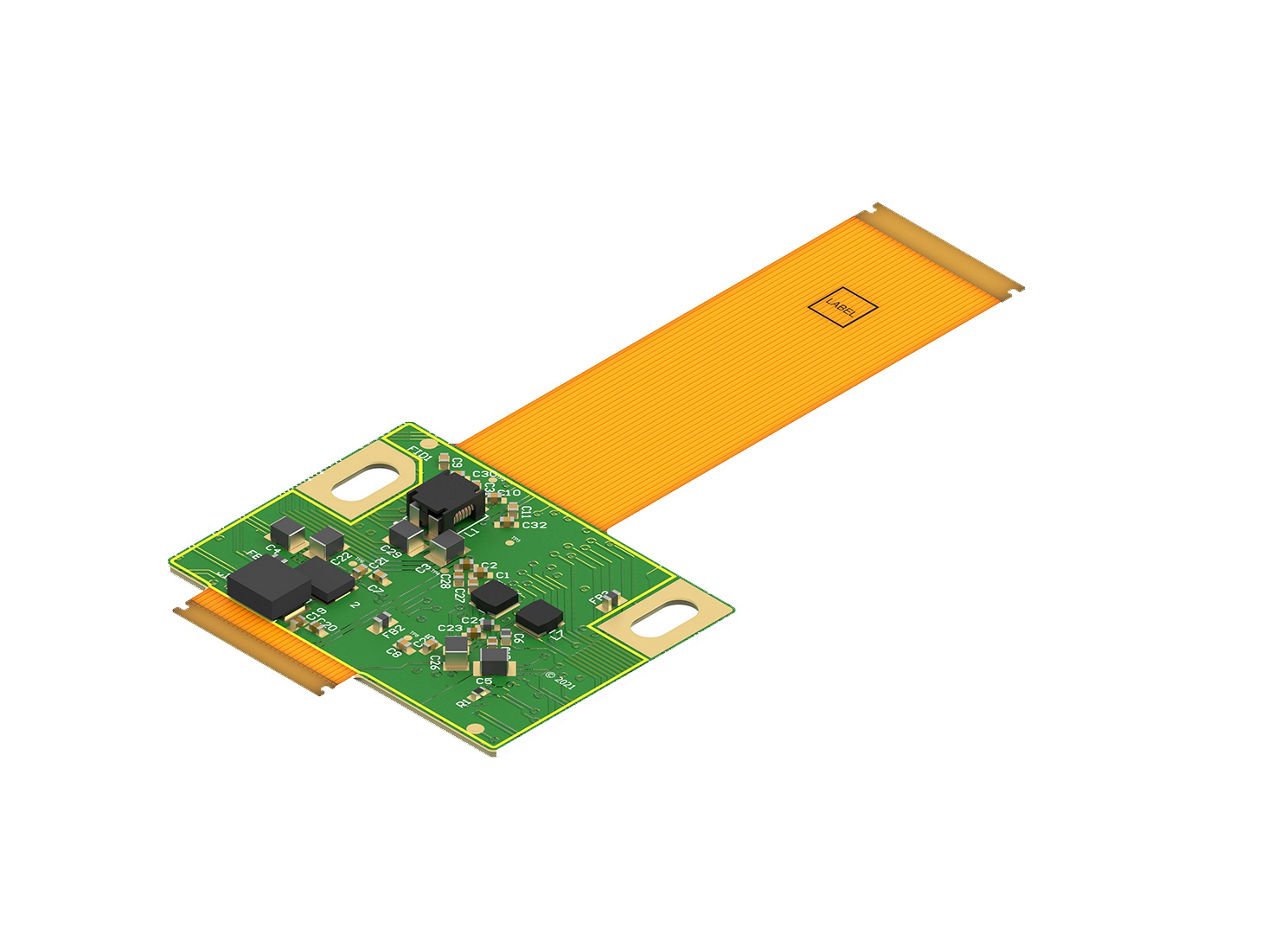
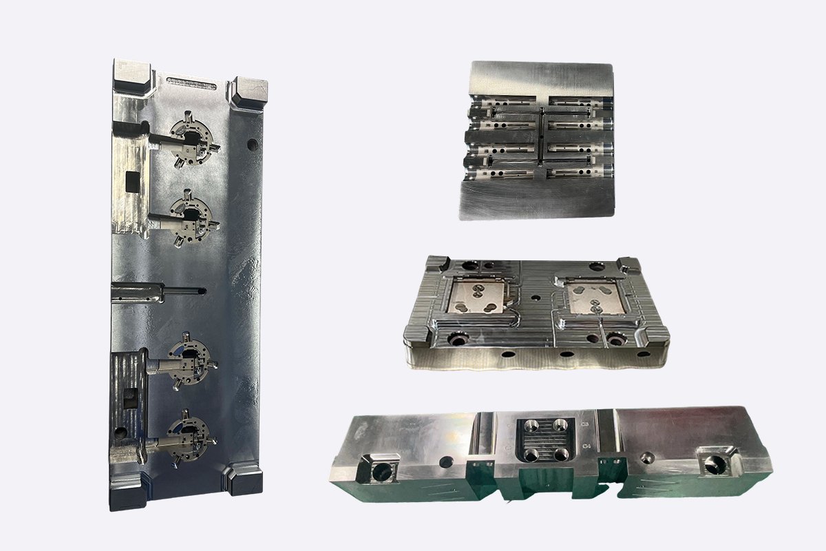
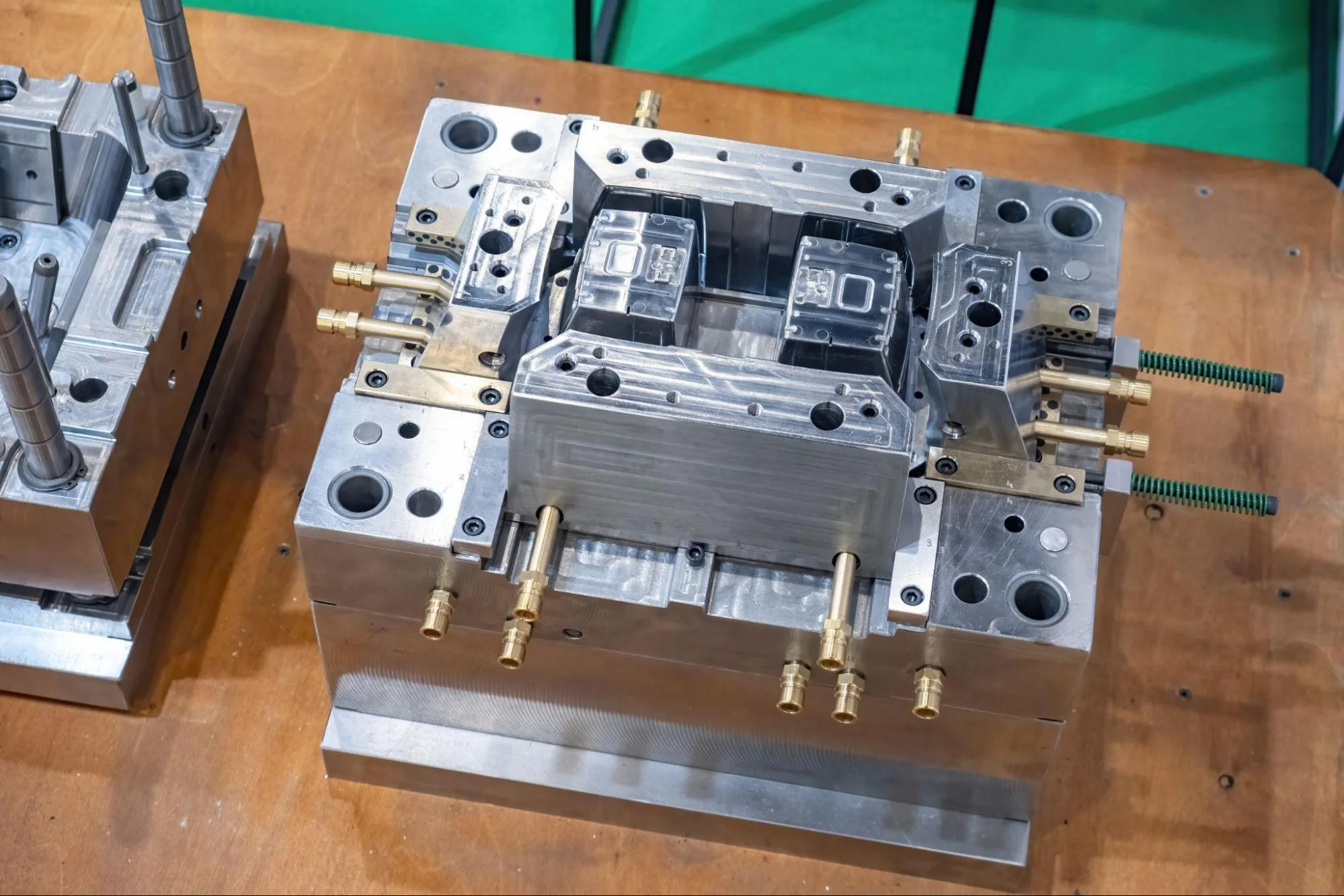
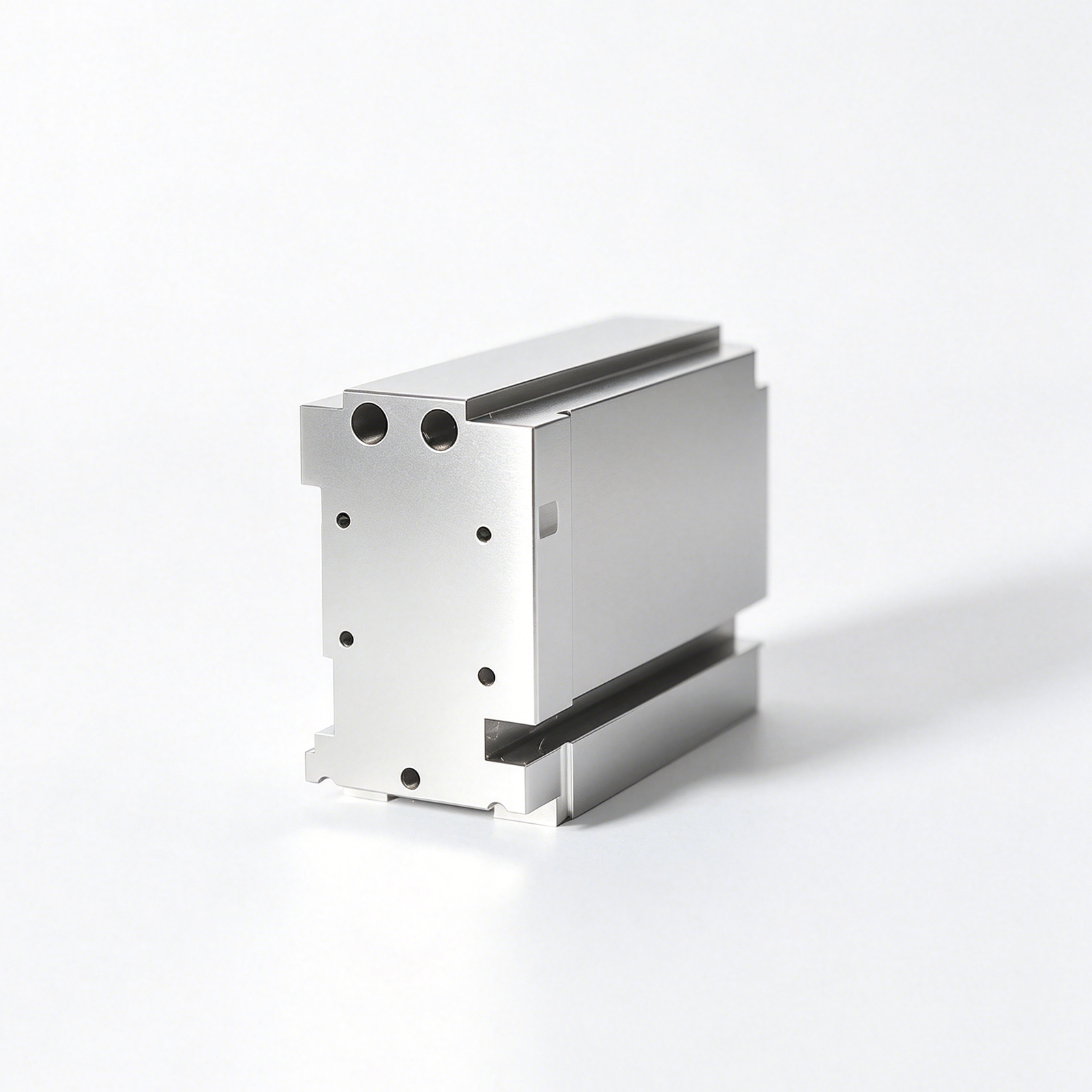
Precision Mold Components in Action


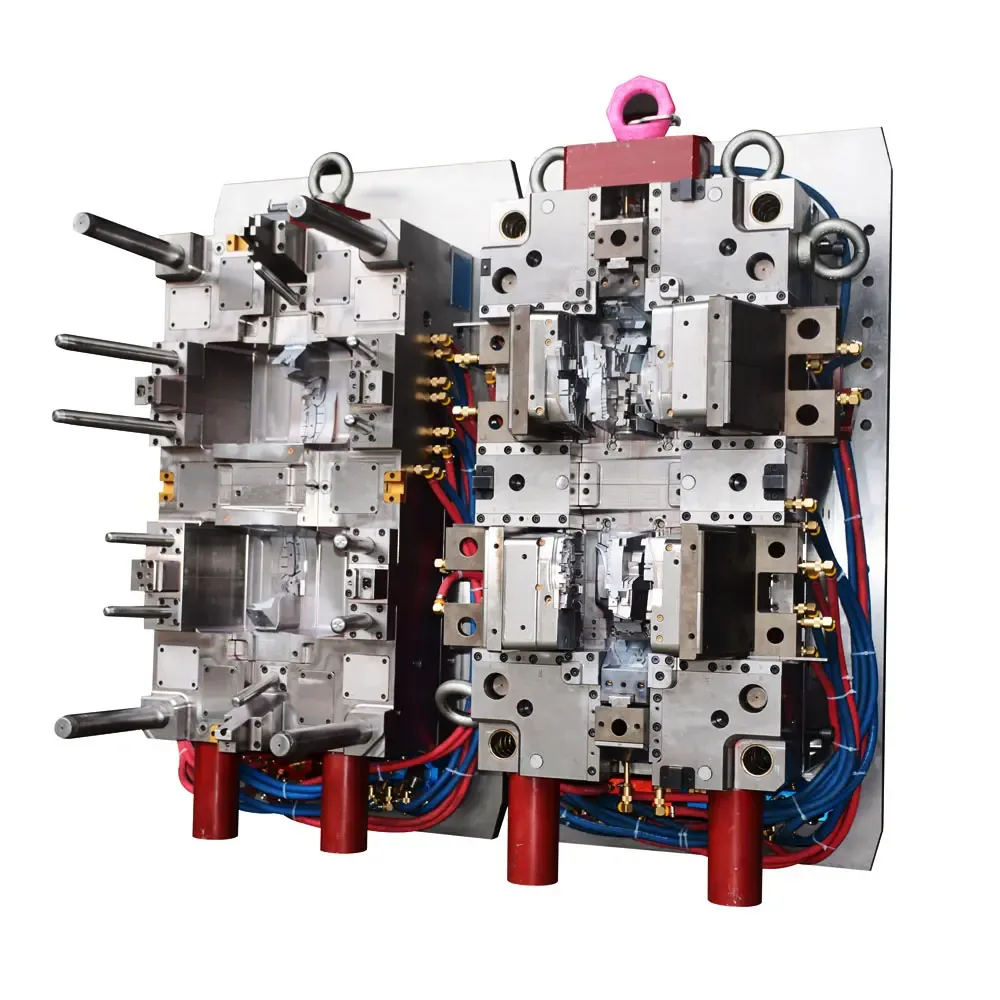
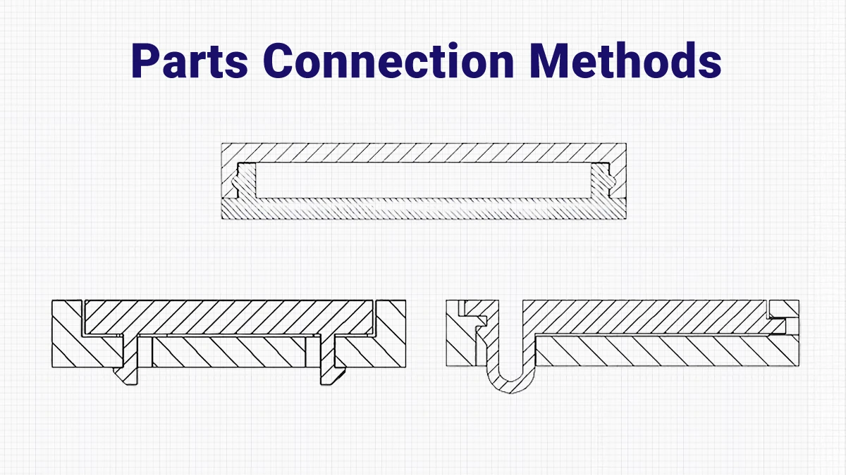
Why XUXIANG Electronic Components Mold Stands Apart
+/-0.001 mm Machining Precision
Micron-stable accuracy on every electronic components mold part, validated with ZEISS MICURA CMM metrology to 0.7um and backed by Sodick slow-wire EDM.
Mirror-Grade EDM Surface Finish
Ra 0.1um mirror-class finishes delivered by Mitsubishi mirror EDM and Sodick sinker systems for flawless cosmetic and functional mold surfaces.
ZEISS CMM & Nikon Metrology
Every electronic components mold undergoes five-step QC with ZEISS MICURA CMM (0.7um resolution), Nikon toolmaker’s microscopes (V-12B / MM-400 class) and full FAI documentation before shipment.
24-Hour Quote Turnaround
Upload your CAD files and receive a detailed, engineering-reviewed quotation within 24 hours, accelerating procurement cycles and project timelines.
Dual-Factory Production Capacity
Dongguan R&D hub plus Quanzhou volume facility totaling 3,400 m² delivers 200% capacity expansion and 30% faster lead times since 2025.
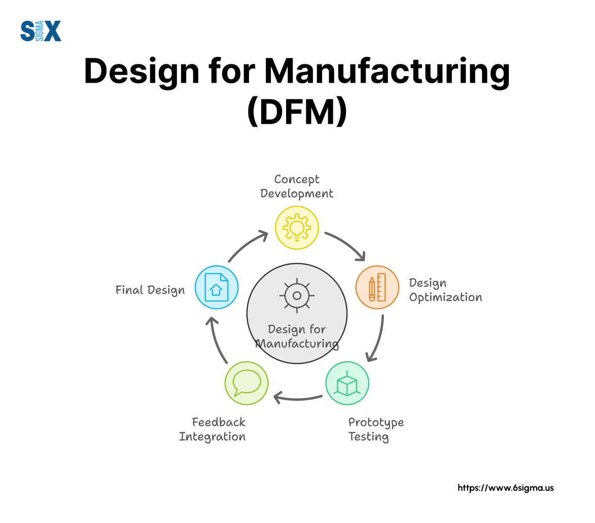
DFM Engineering Support
10+ precision-mold experts review every electronic components mold design for manufacturability, tolerance optimization and cost efficiency before production starts.
Precision Mold Solutions by Component Type
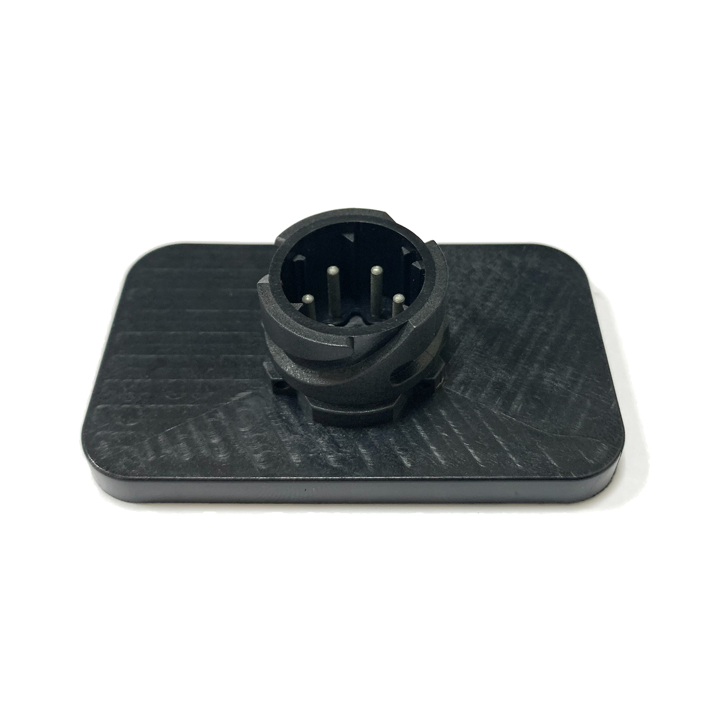
Connector Mold Inserts
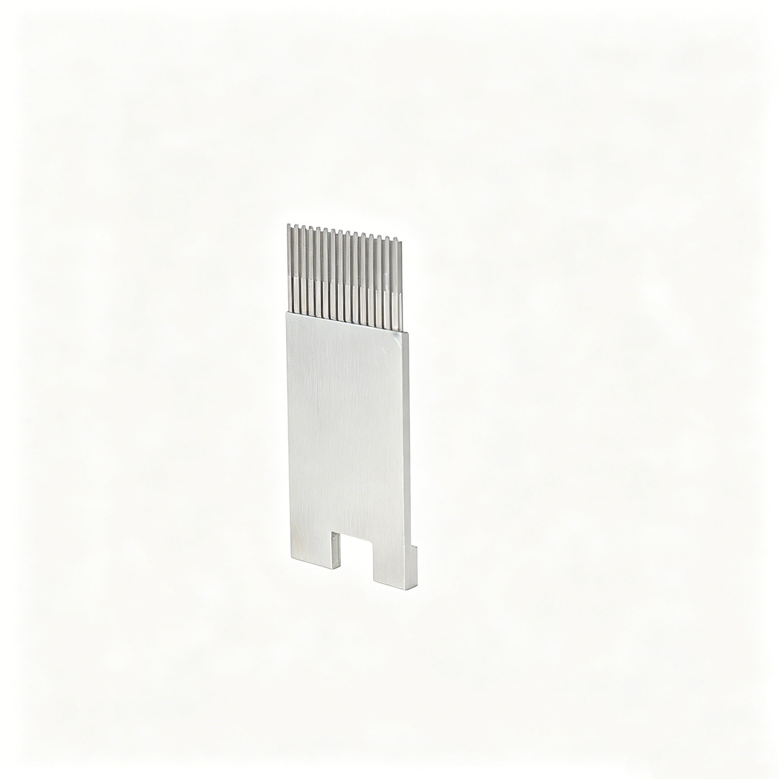
High-density connector mold inserts for 5G, mobile and automotive applications, machined to +/-0.002 mm on Sodick slow-wire EDM. Supports thin-wall micro-pin geometries, board-to-board connector mold components, FPC and RF terminal tooling with mirror-grade Ra 0.1um finishes and full DFM validation from our engineering team.
Get a Quote
IC Package Molds
IC package mold tooling for semiconductor and electronics OEMs requiring micron-stable cavity positioning and thermal uniformity. ZEISS MICURA CMM verification to 0.7um, material certificates included, and lead times 30% faster than industry average for both prototype and volume production runs.
Get a Quote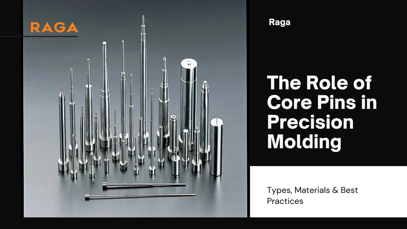
Precision Core Pins
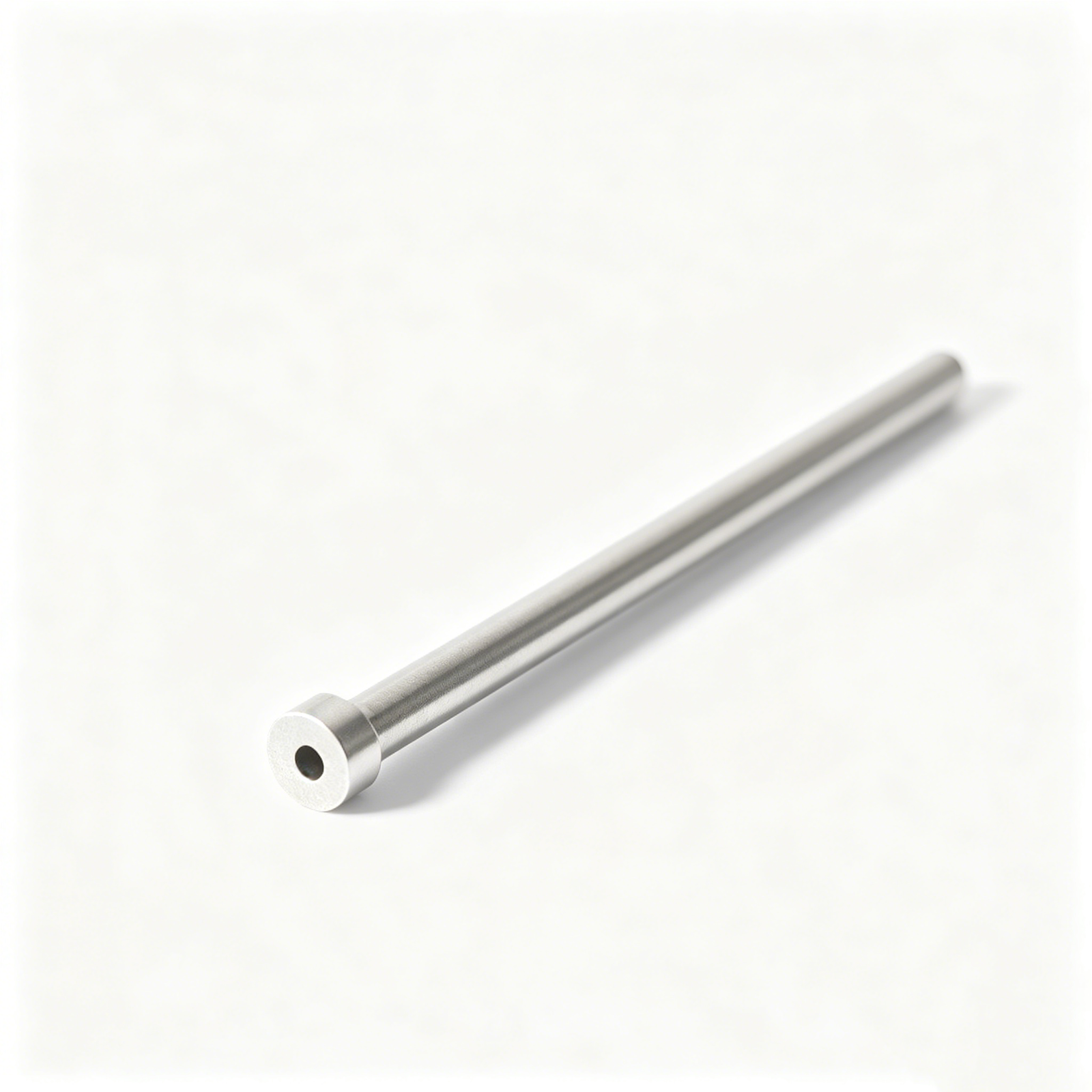
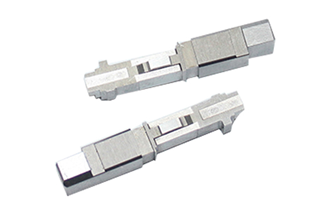
Precision core pins and ejector pins held to +/-0.001 mm diameter tolerance, ground on Dawn precision grinding centers and inspected under Nikon toolmaker’s microscopes. Designed for high-cycle plastic injection molds in automotive sensor housings, medical devices and industrial connectors where wear resistance and straightness are critical.
Get a Quote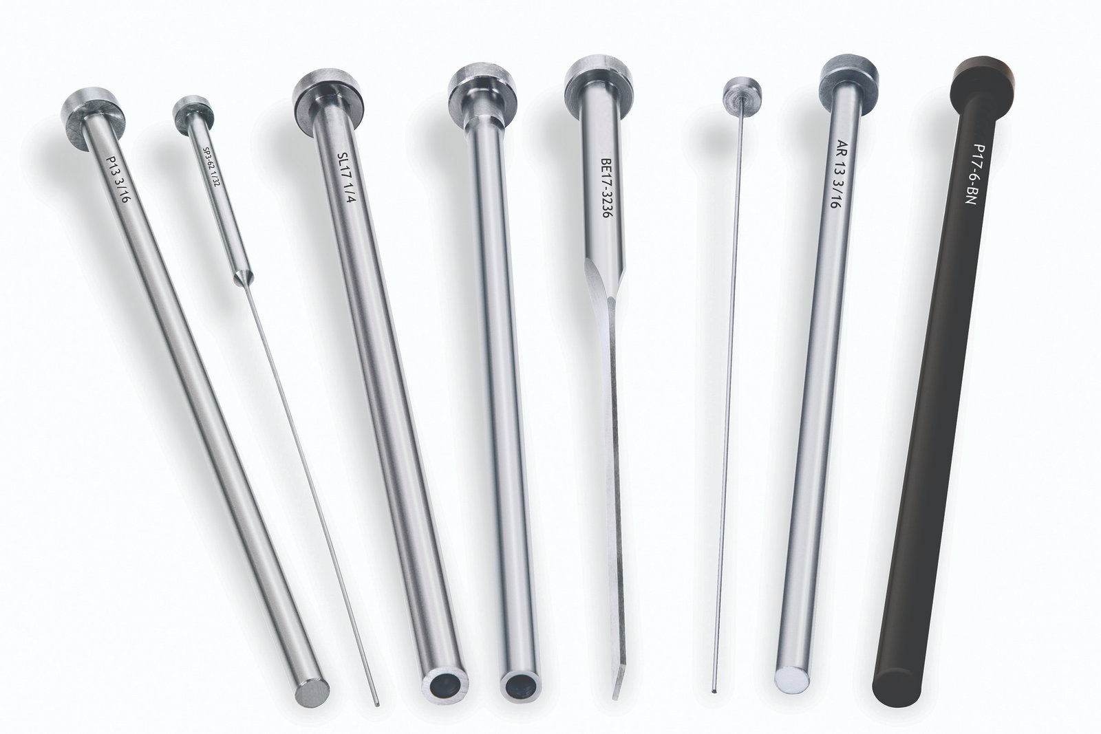
Ejector Pin Systems
Complete ejector pin systems including return pins, sleeves and guided assemblies, machined from SKD61, SKH51 or tungsten carbide. Five-step QC flow ensures concentricity, surface hardness and fatigue life, with FAI documentation and spectral material analysis provided for every batch.
Get a Quote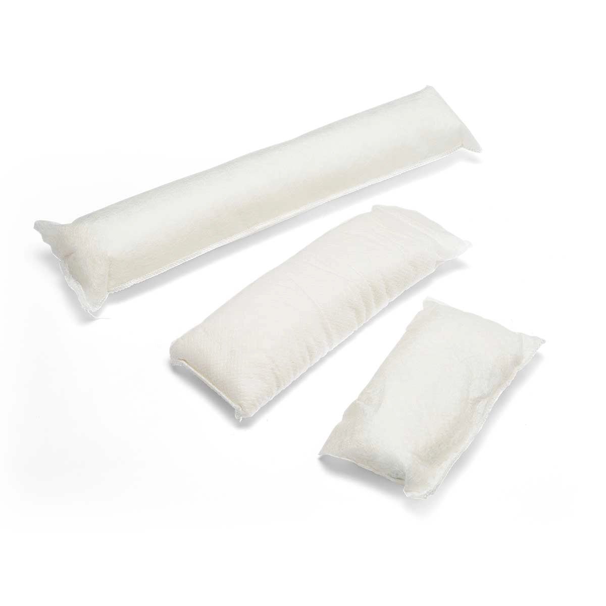
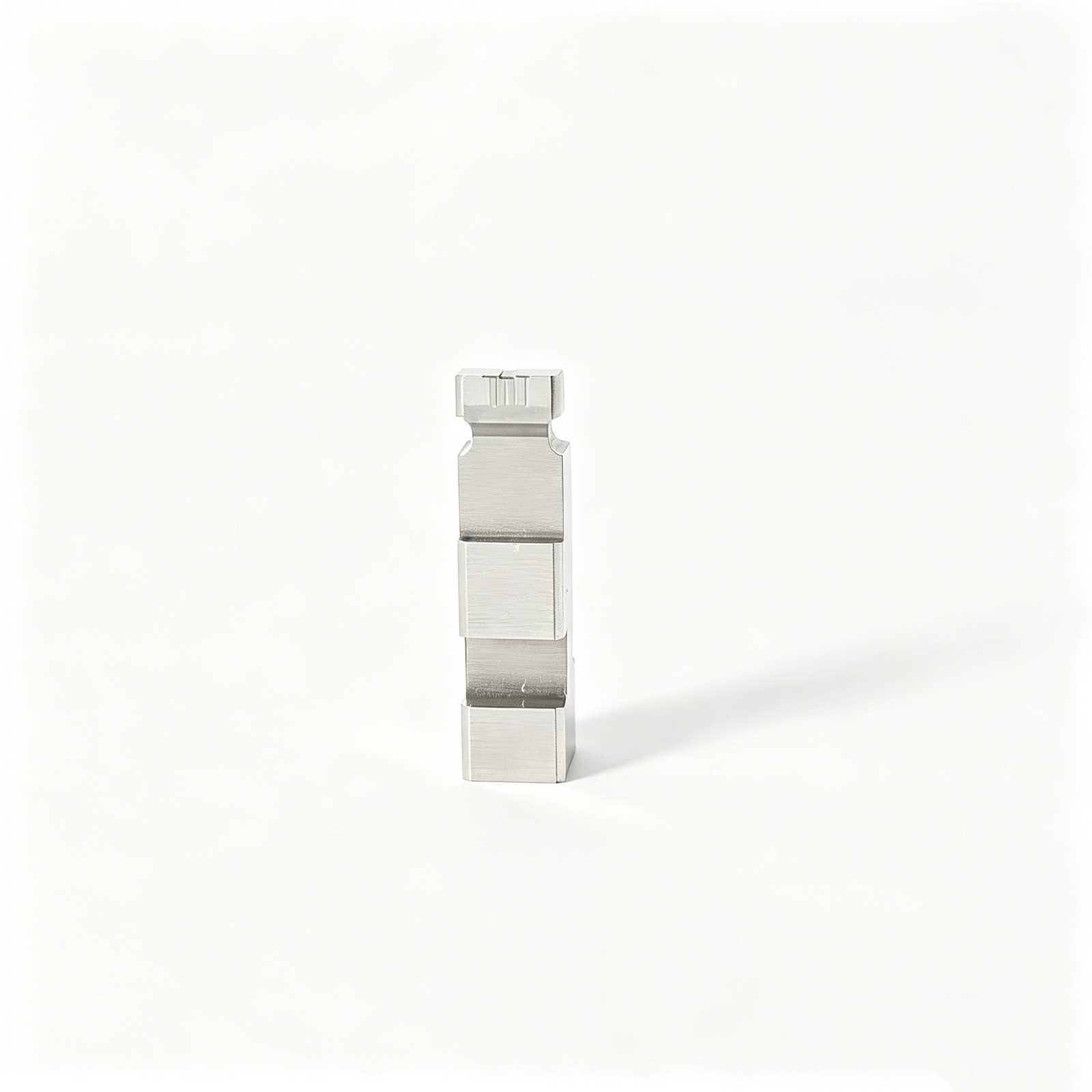
Cavity Inserts
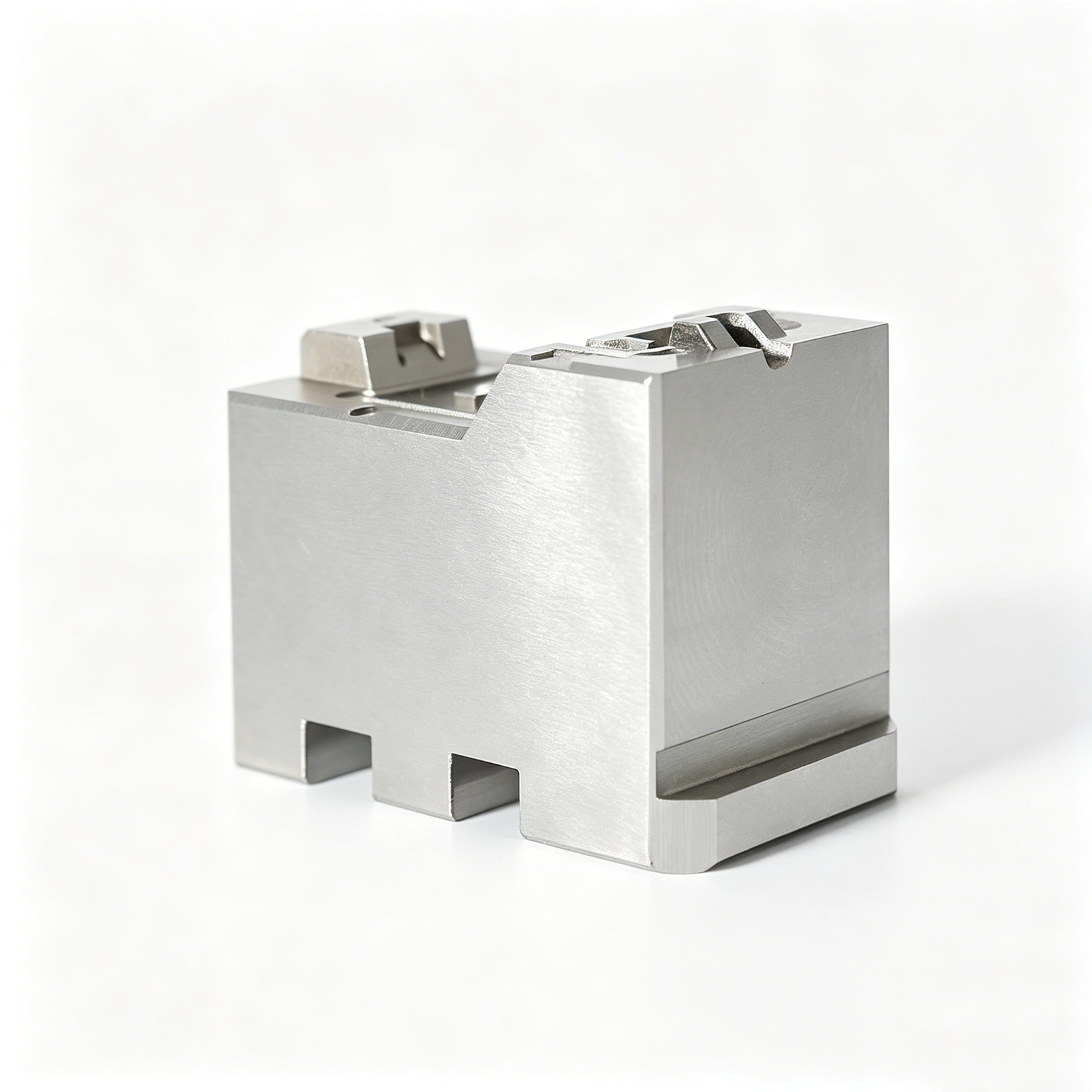
Multi-cavity inserts and core blocks for complex plastic injection molds, featuring conformal cooling channels, mirror EDM finishes and tight inter-cavity positional accuracy. Mitsubishi mirror EDM and Sodick sinker EDM deliver Ra 0.1um surfaces, reducing post-polish time and enabling faster mold commissioning.
Get a Quote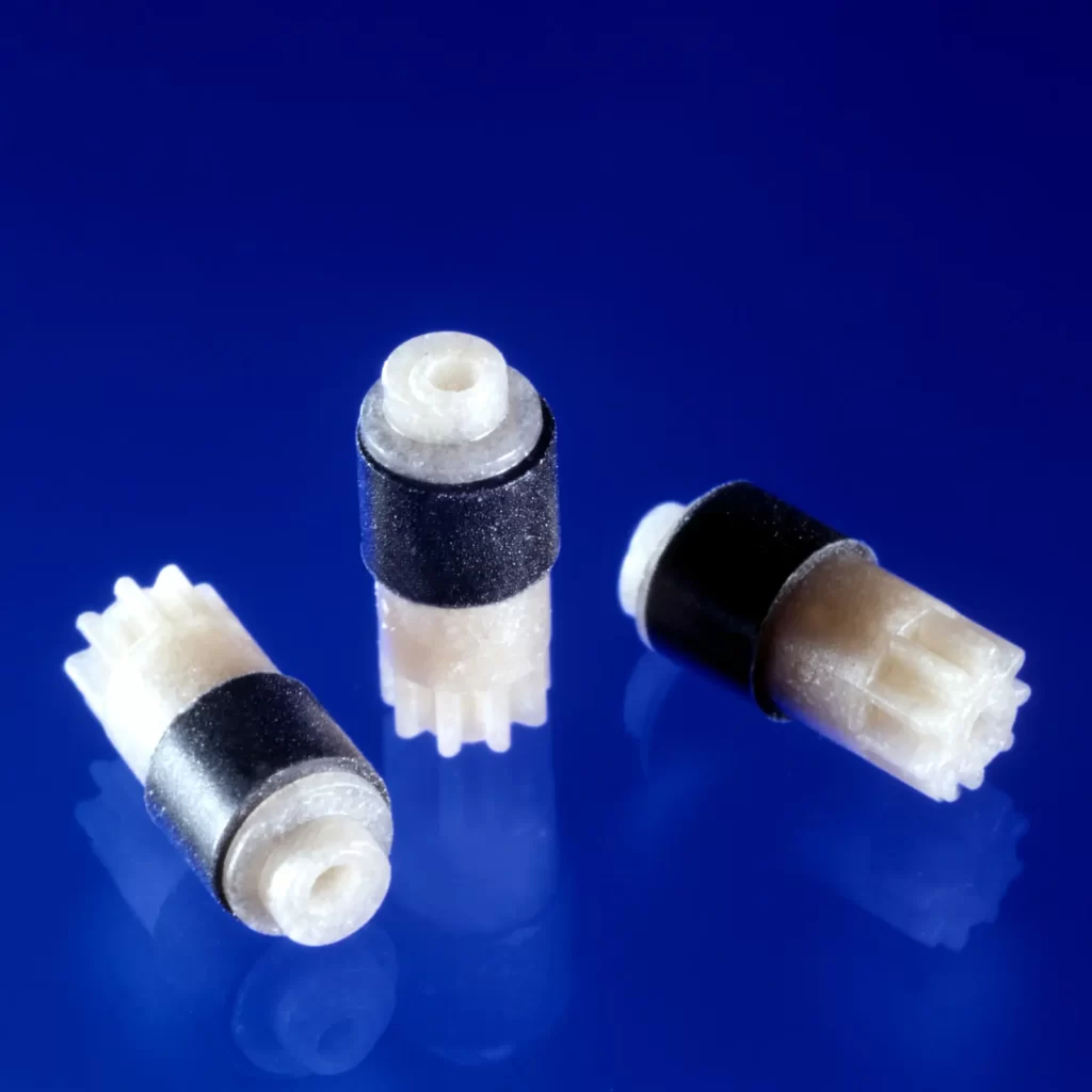
Micro Mold Components
Micro mold components for medical-device, 5G micro-connector and miniature sensor applications where feature sizes approach 0.1 mm and corner radii reach R 0.015 mm. Beijing Jingdiao high-precision CNC and slow-wire EDM achieve geometries unattainable by conventional machining, backed by Nikon MM-400 class optical metrology.
Get a Quote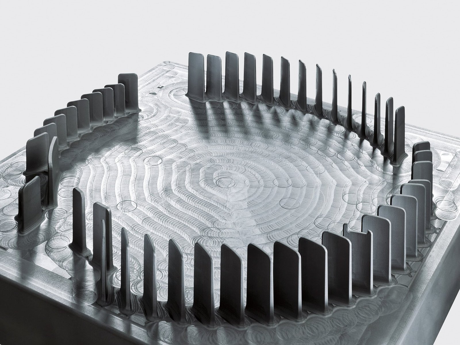
EDM Electrodes
EDM graphite and copper electrodes fabricated on Beijing Jingdiao CNC with +/-0.003 mm form accuracy, supporting sinker EDM of deep ribs, undercuts and complex core details. Electrode libraries maintained for repeat tooling programs, ensuring consistent geometry and faster turnaround on mold revisions.
Get a Quote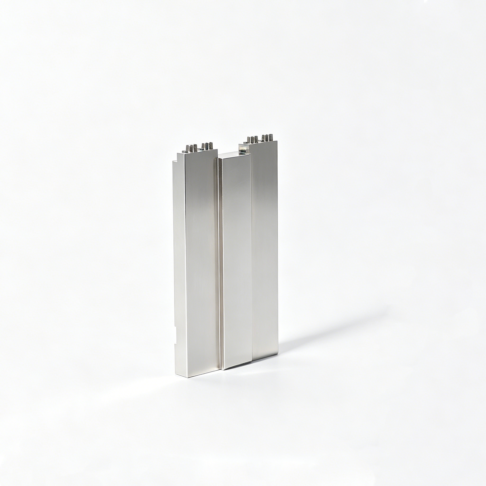
Mold Base Plates
Precision-ground mold base plates in P20, 718H, NAK80 and S136, machined flat to +/-0.005 mm over 500 mm span and stress-relieved for dimensional stability. Fanuc CNC milling and grinding centers deliver parallel faces, tapped holes and dowel-pin register within +/-0.01 mm, ready for insert assembly.
Get a Quote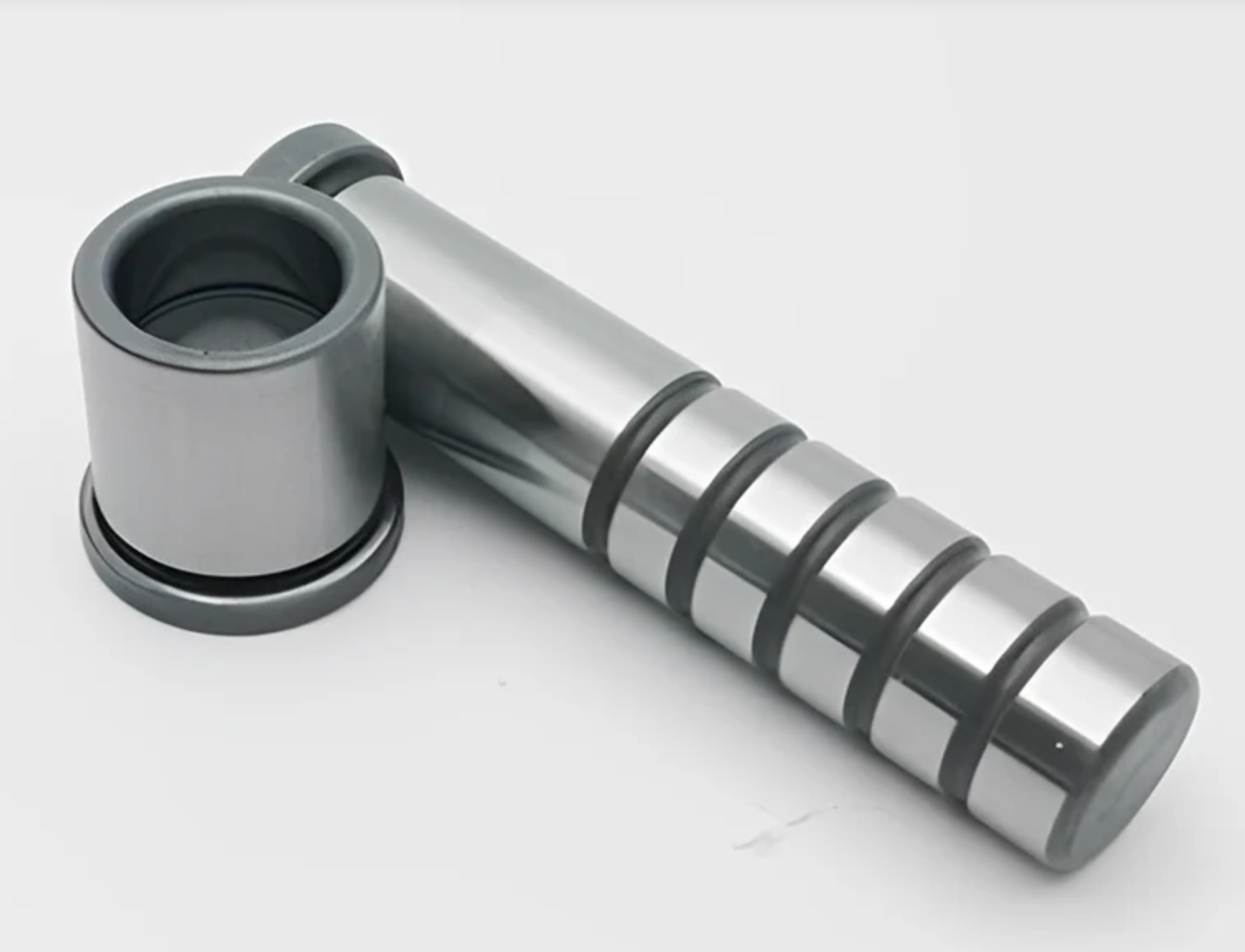
Guide Pin Bushings
Guide pin and bushing sets machined from SUJ2 bearing steel or bronze alloy, held to +/-0.002 mm diameter and cylindricity tolerance. Precision grinding and lapping ensure smooth sliding fit, extended tool life and repeatable parting-line alignment across hundreds of thousands of injection cycles.
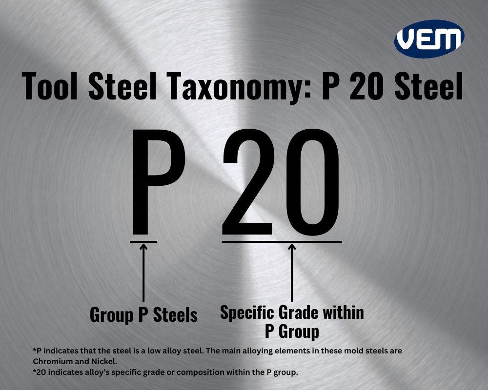
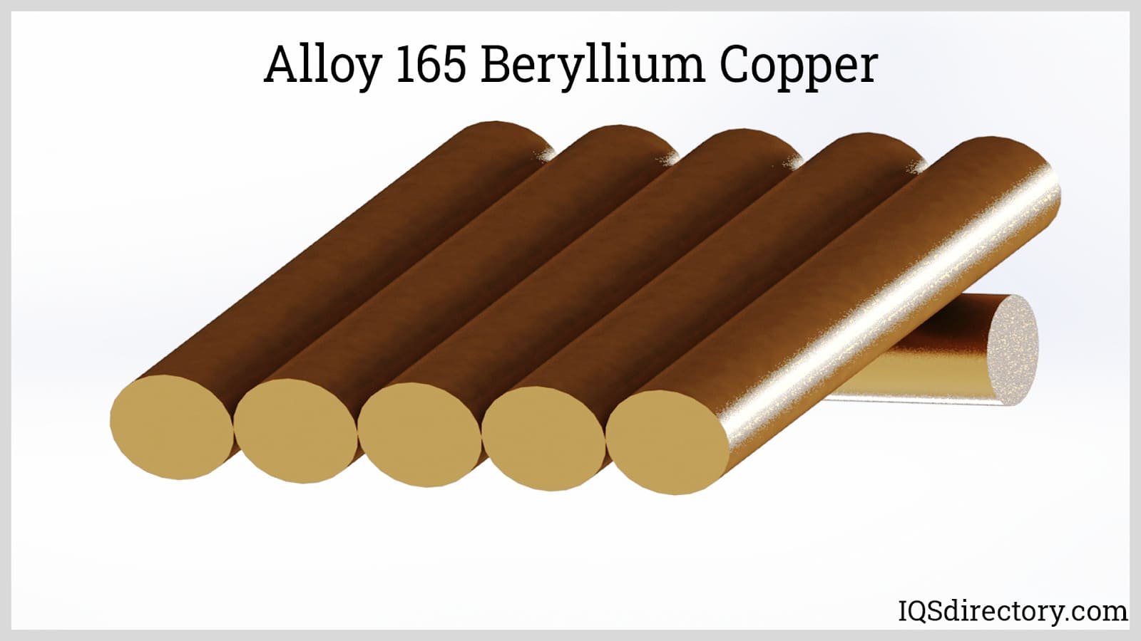
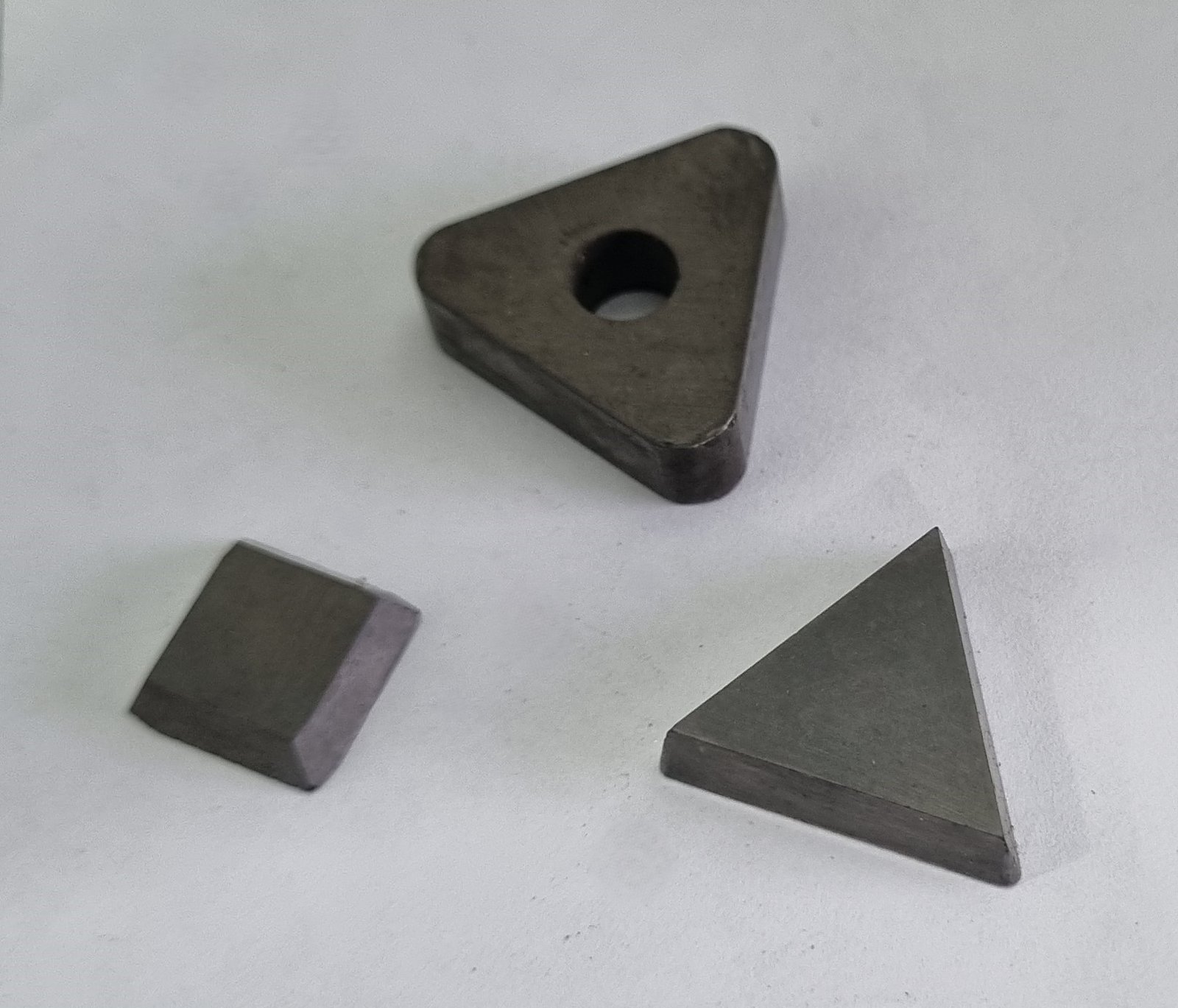
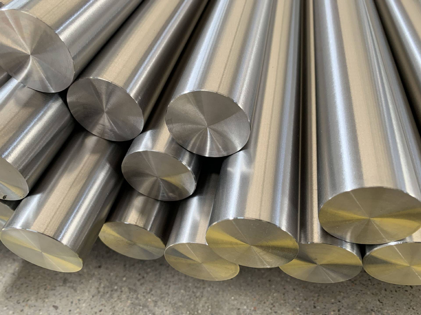
Get a QuoteMaterials & Substrates We Master for Electronic Components Mold
Precision Processes Behind Every Electronic Components Mold
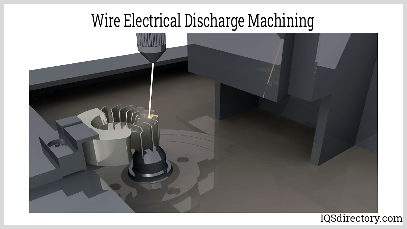
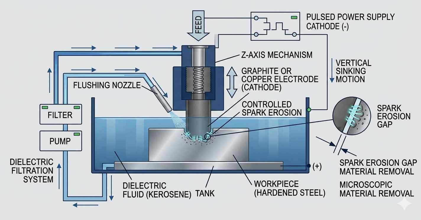
Sinker (Mirror) EDM
Mitsubishi mirror-grade sinker EDM achieves Ra 0.1 µm surface finish on cavity cores and deep ribs, eliminating manual polishing steps. Delivers optical-class textures for electronic housings, micro-connectors and precision inserts requiring minimal post-processing.
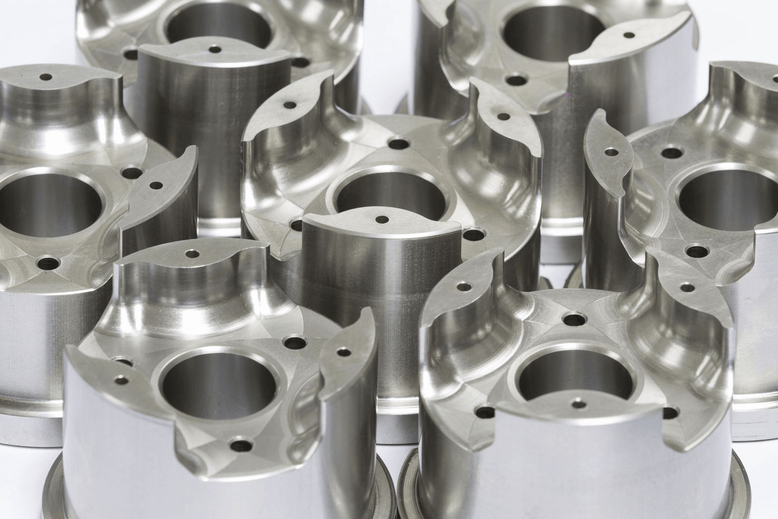


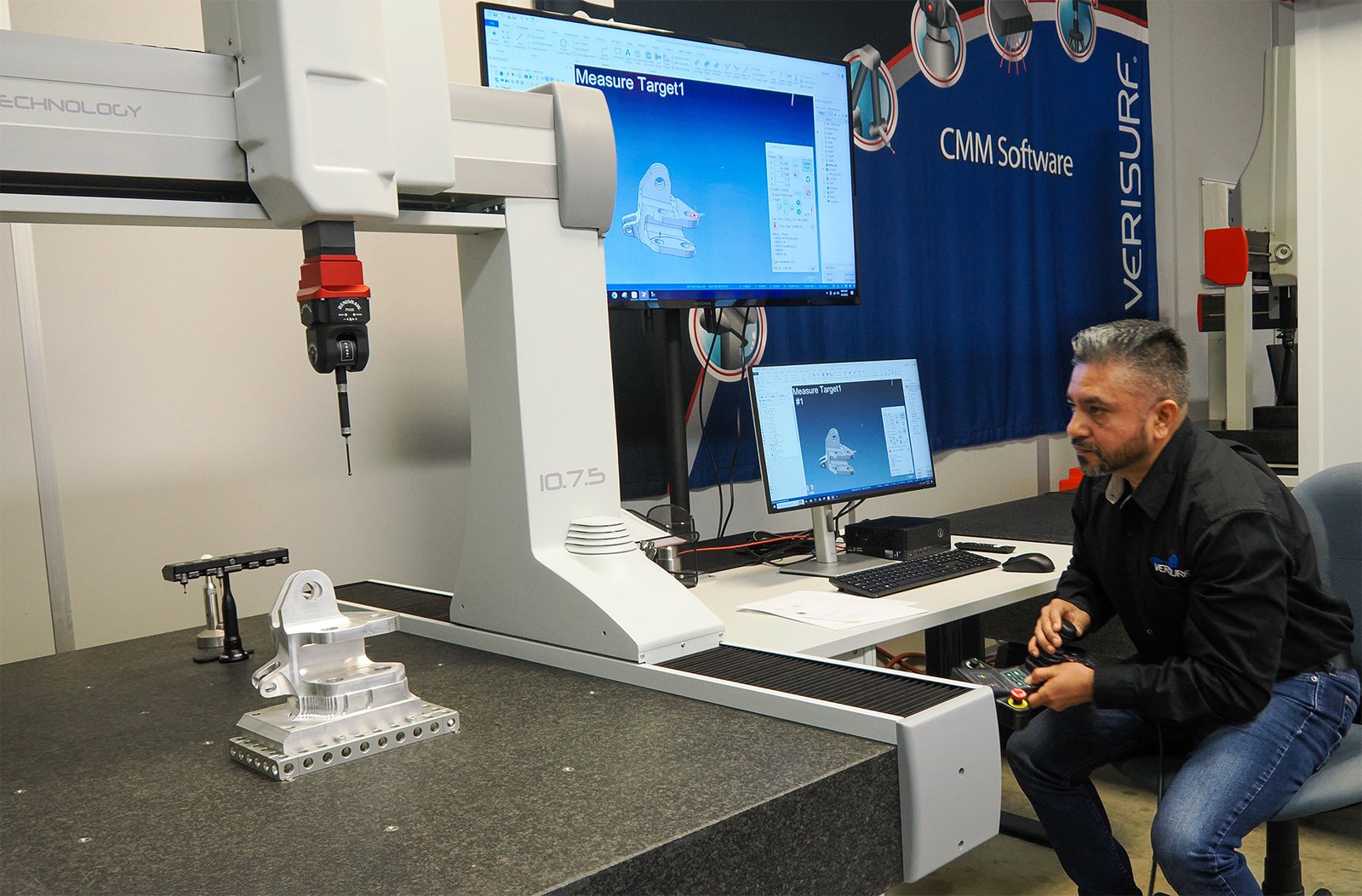
CMM Metrology
ZEISS MICURA coordinate measuring machine (0.7 µm resolution) and Nikon toolmaker’s microscopes verify every critical dimension, flatness, perpendicularity and profile tolerance. Full FAI reports and material certificates accompany every shipment for traceability and audit compliance.
Electronic Components Mold Accessories & Core Parts
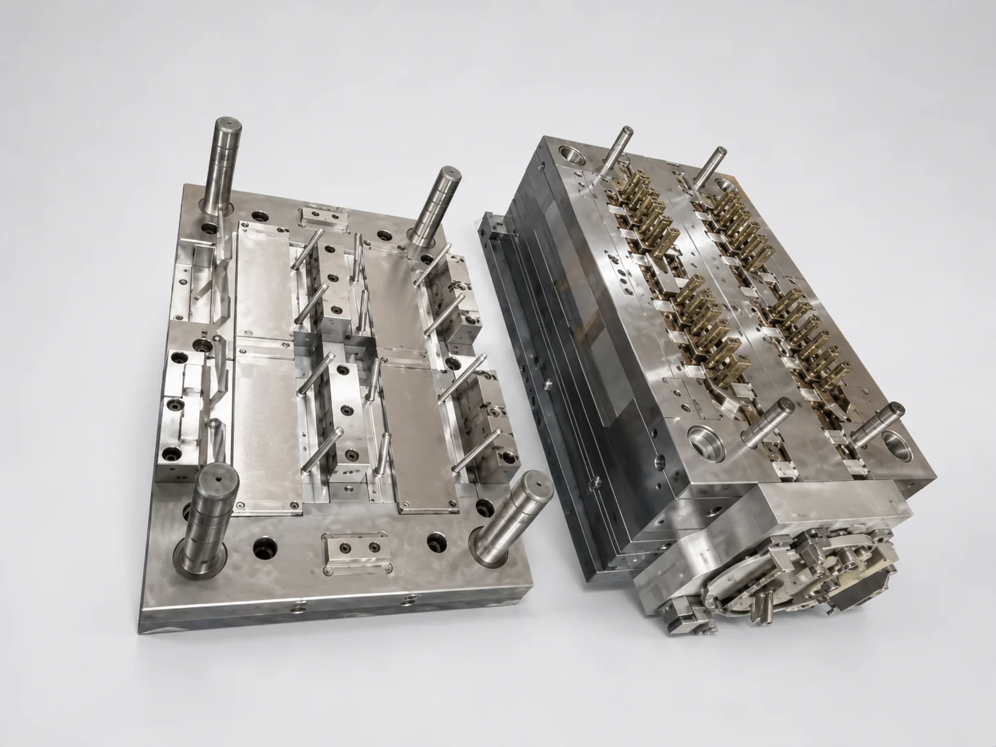

Conformal Cooling Channels
3D-contoured cooling circuits that follow part geometry for uniform heat extraction. Designed via DFM simulation and machined or additively integrated to reduce cycle time by 20–30% in high-thermal-load electronics molds.
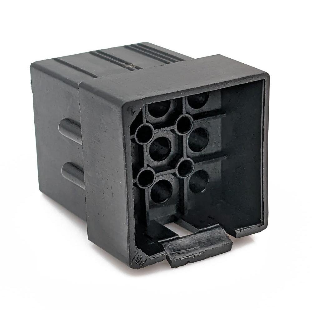
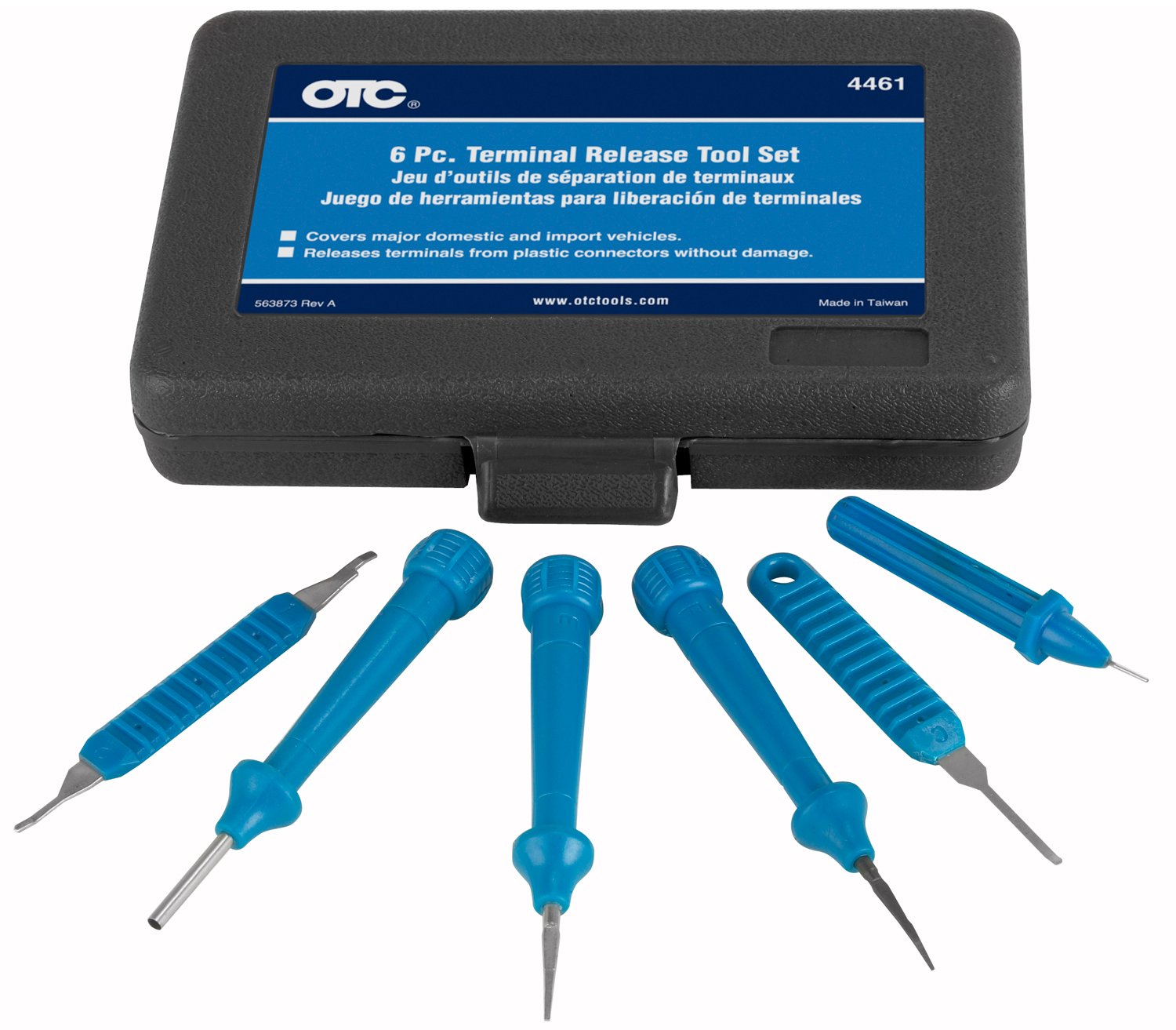
Terminal Tooling
Precision inserts for stamping and molding high-density terminals in automotive HV/BMS connectors and industrial automation. +/-0.003 mm EDM tolerance, full FAI documentation, compatible with both insert-molding and progressive-die workflows.
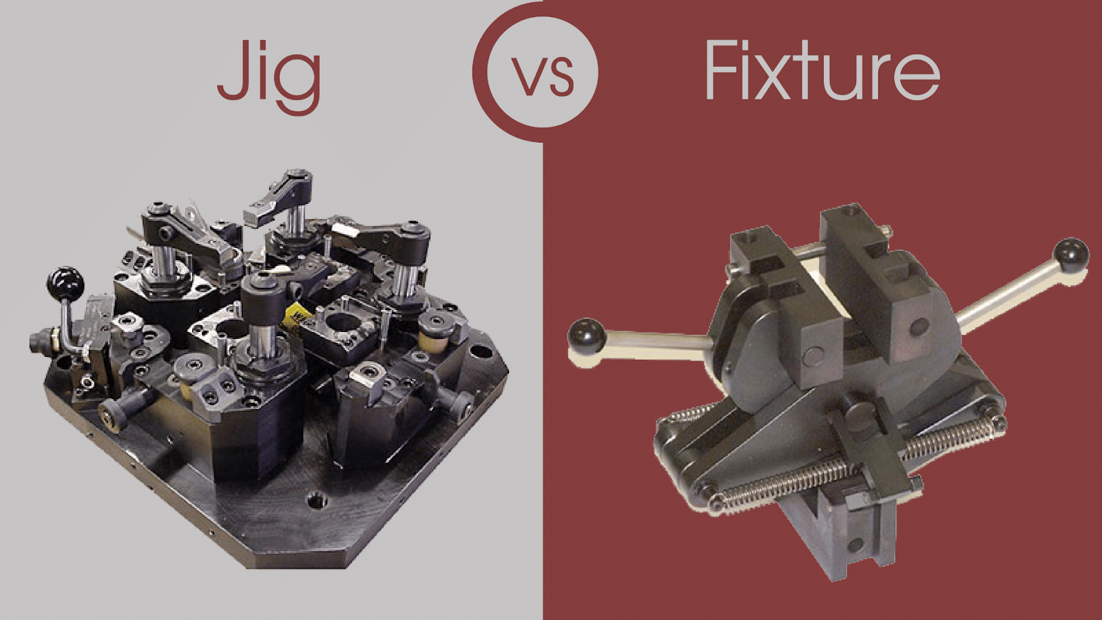
Jigs & Fixtures
Custom work-holding and inspection fixtures for CNC, EDM and assembly of electronic components. Fanuc CNC-machined with repeatable location accuracy to +/-0.001 mm, reducing setup time and ensuring part-to-part consistency.
About XUXIANG — 16 Years of Precision Mold Engineering
Founded in 2010 in Chang’an, Dongguan, XUXIANG began as a specialist mold-core machining shop and has grown into a dual-factory precision manufacturing group serving electronics, 5G/telecom, automotive & NEV, industrial-automation and medical-device customers worldwide. Our mission: bridge the gap between complex CAD designs and high-performance physical parts for electronic components mold and micro-connector tooling applications.
Today we operate 2,000 m² of R&D and micro-machining capacity in Dongguan, plus a 1,400 m² volume-production facility in Quanzhou launched in 2025—boosting annual output by over 200%. Backed by more than CNY 8 million invested in Sodick slow-wire EDM, Mitsubishi mirror EDM, Fanuc CNC and ZEISS MICURA CMM metrology, we deliver +/-0.001 mm machining precision and Ra 0.1um mirror-grade finishes under ISO 9001:2015 governance.
What sets XUXIANG apart is a precision-first culture: every project receives DFM feedback from 10+ engineering experts, five-step QC validation with full FAI documentation, and lead times roughly 30% faster than industry norms. We don’t just manufacture parts—we solve tolerance failure and delivery delay with engineering rigor, verifiable data and transparent partnership.
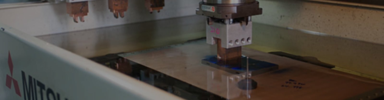
Electronic Components Mold: Tolerance, Speed & Validation
Micron-Stable Precision for Critical Geometries
XUXIANG delivers +/-0.001 mm machining accuracy, Ra 0.1um mirror-grade EDM finishes, and corner radii down to R ≤ 0.015 mm—the tolerances that define high-performance electronic components mold tooling for 5G connectors, automotive sensors and medical housings.
- Sodick & Seibu slow-wire EDM achieving +/-0.002 mm class positioning on micro-pin and socket cavities
- Mitsubishi mirror EDM for Ra 0.1um surface integrity on optical-grade inserts
- ZEISS MICURA CMM (0.7um resolution) and Nikon toolmaker's microscopes validate every critical dimension
- Beijing Jingdiao high-precision CNC for electrode fabrication and conformal cooling channels

Rapid Turnaround Without Tolerance Compromise
Speed matters when launch windows are tight. XUXIANG returns quotes in 24 hours, ships samples in 3–7 days, and completes mass production in 15–25 days—roughly 30% faster than industry average—while holding micron-class tolerances throughout.
- 24-hour quotation turnaround with detailed DFM feedback from 10+ engineering experts
- 3–7 day sample delivery for first-article validation and design iteration
- 15–25 day mass-production lead times supported by dual-factory capacity (Dongguan + Quanzhou)
- 2025 Quanzhou expansion adds ~1,400 m² and +200% annual output for scalable volume
Full-Cycle DFM & FAI Documentation
Every electronic components mold project is engineered before it is machined. XUXIANG’s 10+ in-house experts review geometry, draft angles, ejection and cooling—then validate through a five-step QC flow that includes material spectral analysis, in-process monitoring, CMM verification, surface-integrity checks and complete FAI reports.
- Pre-production DFM consultation identifies tolerance risks, undercuts and cooling optimization
- Five-step ISO 9001:2015 quality flow from raw-material inspection to final dimensional validation
- ZEISS MICURA CMM and Nikon V-12B / MM-400 class microscopes confirm sub-micron repeatability
- Every shipment includes full FAI documentation, material certificates and inspection reports
Why XUXIANG Electronic Components Mold Outperforms Standard Suppliers
When precision, speed and documentation matter, the differences are measurable. Compare our micron-stable tooling capabilities against typical mold shops.
← 左右滑动查看 →
XUXIANG’s Electronic Components Mold Production & Quality Flow
From design review to final inspection, every electronic components mold passes through seven control gates engineered to eliminate tolerance failure and delivery delay.
Design Review & DFM
10+ engineering experts analyze your CAD files, flag tolerance risks, suggest process optimizations and confirm manufacturability before machining begins — preventing costly rework downstream.
Material Verification
Spectral analysis validates alloy composition and hardness against your specification. Every batch ships with traceable material certificates for full supply-chain transparency.
Precision Machining
Sodick slow-wire EDM, Mitsubishi mirror EDM, Fanuc CNC and Dawn grinding centers machine cores, inserts and electrodes to +/-0.001 mm, with Ra 0.1um mirror finishes.
In-Process Tolerance Monitoring
Operators measure critical dimensions at each setup change using calibrated micrometers and toolmaker’s microscopes, ensuring drift stays within +/-0.002 mm class limits.
ZEISS & Nikon CMM Validation
ZEISS MICURA CMM measures to 0.7um resolution; Nikon V-12B and MM-400 class microscopes verify corner radii, edge breaks and micro-features against your print.
Surface Integrity & FAI
Final surface-roughness checks, dimensional first-article inspection and photographic documentation compile into a complete FAI package with material certs, ready for your incoming QC.
How to Order Your Electronic Components Mold
From CAD submission to validated production parts, XUXIANG‘s five-step process ensures micron-stable precision, transparent communication and on-time delivery for every electronic components mold project.
Submit CAD & Technical Requirements
Upload your 3D files, drawings and tolerance specifications. Our engineering team reviews your electronic components mold design for manufacturability and material compatibility within hours.
Receive DFM Feedback & Quote
Within 24 hours, 10+ DFM experts deliver process recommendations, tolerance validation and a transparent quote—no hidden costs, no ambiguity, just engineering clarity.
Approve Sample Order
Confirm your sample order and XUXIANG machines your first-article parts in 3–7 days using Sodick EDM, Fanuc CNC and ZEISS CMM validation to +/-0.001 mm.
Validate Samples & FAI Report
Inspect first-article samples alongside full FAI documentation, material certificates and dimensional reports. Approve fit, finish and function before scaling to production volume.
Place Bulk Production Order
Launch mass production with 15–25 day lead times. Every electronic components mold shipment includes traceability documentation, in-process QC records and ISO 9001:2015 compliance certification.
Certifications & Quality Standards for Electronic Components Mold



Electronic Components Mold Success Stories
XUXIANG delivered 2,400 multi-cavity electronic components mold inserts at +/-0.0015 mm tolerance with zero rework. Our 5G connector production yield jumped 18% in the first quarter, and lead times dropped by 30%.
We switched to XUXIANG for automotive sensor housing molds after repeated tolerance failures elsewhere. They reduced our defect rate from 12% to under 0.5% in six months — mirror EDM finish and ZEISS validation on every batch.
For our medical-grade micro-connector tooling, XUXIANG hit +/-0.001 mm on 1,800 precision cores with full FAI documentation and material certs. Their DFM feedback caught three design risks before production — saved us weeks and significant rework costs.
FAQ: Electronic Components Mold & Precision Tooling
What is the minimum order quantity for electronic components mold parts?
What are the lead times for electronic components mold samples versus mass production?
Do you charge for samples, and what are your payment terms?
How does XUXIANG protect my designs and intellectual property?
Can XUXIANG provide DFM feedback for electronic components mold designs?
What tolerance guarantees do you offer on precision mold components?
Do you source materials, or must I supply them?
How do you handle international shipping and logistics?
Can you scale production if my electronic components mold volume increases?
The Complete Buyer’s Guide to Electronic Components Mold for Precision Manufacturing
Navigate supplier selection, material choices, and quality benchmarks with confidence. This guide delivers a proven decision framework, critical evaluation criteria, and the most common procurement mistakes to avoid when sourcing electronic components mold.
1. What Is an Electronic Components Mold?
An electronic components mold is precision tooling — typically a cavity-and-core set machined from hardened steel or copper alloy — designed to form connectors, housings, terminals, micro-pins and other miniature parts through injection molding, die-casting or metal stamping. Each mold translates a CAD design into repeatable, high-volume physical geometry, often with feature sizes measured in tenths of a millimeter.
Tolerances of +/-0.001 mm (1 micron) are critical because 5G RF connectors, automotive sensor housings and medical-device terminals demand zero positional drift across millions of cycles. A 2-micron shift in a board-to-board socket can cause intermittent contact; a 3-micron taper in a molded housing may compromise IP67 sealing. XUXIANG’s ZEISS MICURA CMM measures to 0.7 µm, ensuring every core insert, lifter and ejector pin meets print before the mold ships.
When you purchase an electronic components mold, you are buying both the physical tooling and the engineering validation that guarantees first-article conformance, cycle-time predictability and long-term dimensional stability under production heat and pressure.
2. Evolution of Electronic Components Mold Technology
In the 1980s, electronic components mold technology centered on macro-scale plastic enclosures with tolerances of +/-0.05 mm or wider, machined on conventional mills and lathes. The advent of three-axis CNC machining in the 1990s enabled repeatable +/-0.01 mm accuracy, opening the door to smaller connectors and multi-cavity layouts that reduced per-part cost.
The 2000s brought wire-cut EDM and sinker EDM into mainstream mold shops, slicing complex geometries with +/-0.003 mm positioning and mirror-grade Ra 0.1 µm finishes — critical for thin-wall mobile-phone housings and early smartphone micro-USB tooling. Hot-runner systems evolved in parallel, cutting cycle times by 20–30 % and eliminating sprue waste in high-volume runs.
Since 2010, smartphone miniaturization, 5G antenna arrays, NEV battery-management connectors and IoT sensor housings have pushed the floor to +/-0.002 mm slow-wire tolerances and sub-0.015 mm corner radii. Today’s electronic components mold programs integrate five-axis CNC electrode fabrication, conformal cooling and real-time CMM validation — shrinking lead times roughly 30 % while holding micron-stable precision across million-shot lifecycles.
3. Types of Electronic Components Mold
Electronic components mold platforms divide by process and part function. The four primary categories — injection molds for connectors, progressive stamping dies for terminals, die-casting molds for metal housings, and insert/overmolding tooling — each address distinct geometries, cycle economics and tolerance windows.
Injection Molds for Plastic Connectors and Housings
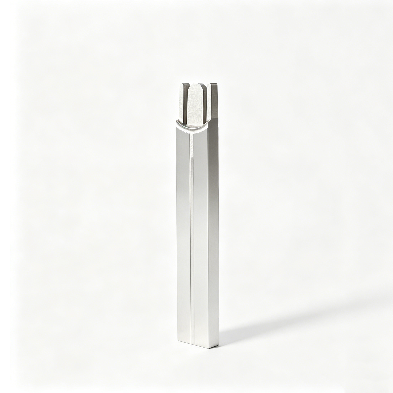
Connector injection molds produce board-to-board, FPC, RF and power housings in multi-cavity layouts ranging from 4 to 32 impressions. Thin-wall sections often run 0.3–0.6 mm, demanding +/-0.002 mm core positioning and mirror-grade EDM finishes (Ra ≤0.2 µm) to prevent flash and ensure contact alignment.
Progressive Stamping Dies for Metal Terminals and Pins
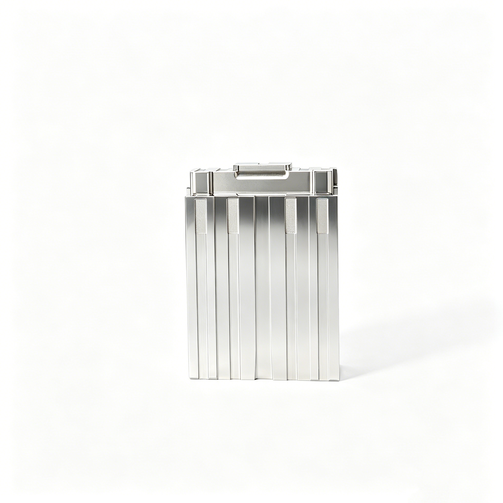
Progressive dies punch, form and trim copper-alloy or phosphor-bronze terminals in continuous strip feed. Typical pitch is 1.27–2.54 mm; dies may integrate 8–20 stations to achieve bend radii ≤0.1 mm and positional tolerances of +/-0.01 mm, critical for high-density interconnects.
Die-Casting Molds for Aluminum and Zinc Housings
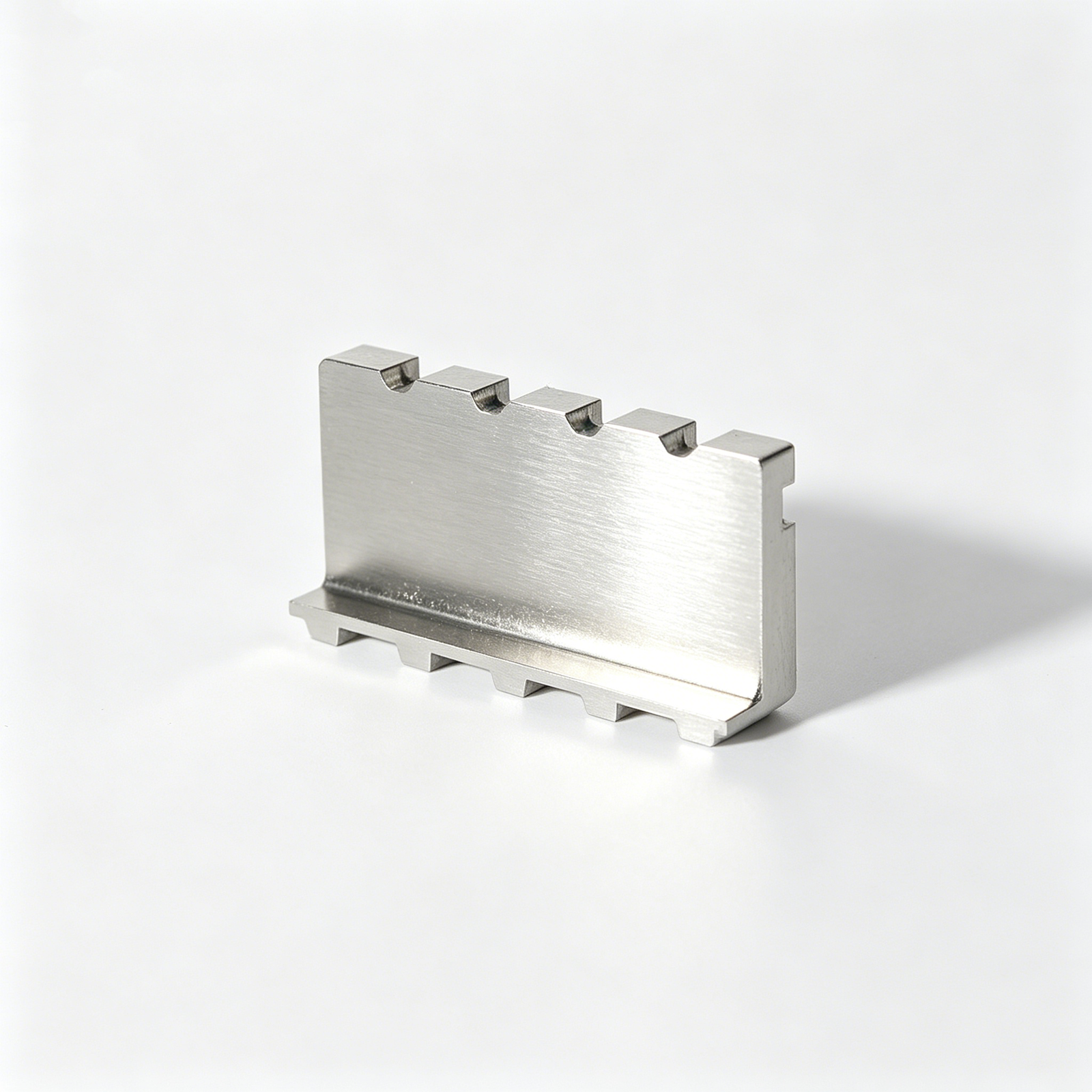
Die-cast tooling for aluminum (ADC12, A380) or zinc (Zamak 3/5) housings supports EMI shielding and heat dissipation in telecom and automotive modules. Cavity counts rarely exceed 4 due to thermal management; draft angles of 1–3° and wall thickness ≥1.0 mm are standard.
Insert and Overmolding Tooling
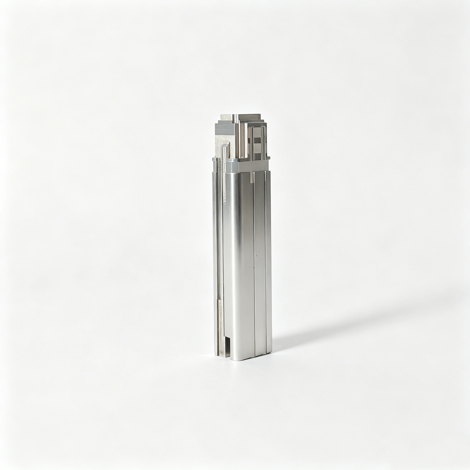
Insert-molding tools encapsulate stamped terminals or threaded inserts during injection, eliminating secondary assembly. Overmolding adds TPE or silicone seals over rigid housings in a two-shot or sequential process, achieving IP67/IP68 ingress ratings with positional repeatability within +/-0.02 mm across cycles.
4. Materials Used in Electronic Components Mold Manufacturing
Material selection directly determines mold lifespan, part quality and production economics in electronic components mold manufacturing. XUXIANG validates every batch with spectral analysis to confirm grade compliance before machining begins.
| Material | Hardness (HRC) | Key Property | Typical Application | Cost Tier |
|---|---|---|---|---|
| NAK80 | 37–43 | Pre-hardened, high polishability | Connector housings, micro-pin inserts | Mid |
| S136 (420 ESR) | 48–52 | Superior corrosion resistance | Medical, moisture-sensitive parts | High |
| H13 (SKD61) | 46–50 | High thermal conductivity | High-cycle production, hot runners | Mid |
| Carbide inserts | ≥70 | Extreme wear resistance | Gate areas, high-abrasion zones | Premium |
| Copper alloy electrodes | — | High conductivity for EDM | Complex cavity burning, fine detail | Low |
5. Customization and Surface-Finishing Options for Electronic Components Mold
Every electronic components mold is a balance of cavity layout, runner architecture, cooling topology and surface finish — choices that directly control cycle time, scrap rate and unit cost. XUXIANG applies DFM feedback from 10+ engineers to optimize each variable before machining begins.
Hot-Runner vs. Cold-Runner Systems
Cold-runner designs cost less upfront but generate 5–15% material waste per cycle; hot-runner systems eliminate sprues, cut cycle time by 10–20 seconds and reduce scrap to near zero, justifying the premium on runs above 50,000 shots.
XUXIANG integrates both architectures, selecting runner type by part geometry, resin flow and production volume to minimize total landed cost.
Cooling-Channel Design
Conformal cooling channels — routed within +/-0.002 mm of part contours via CNC or EDM — cut cooling time by 30–40% versus straight-drilled lines, critical for thin-wall connectors below 0.3 mm.
XUXIANG models thermal gradients in CAE before machining, ensuring uniform crystallinity and sub-0.05 mm warp across multi-cavity layouts.
Surface Finish: Mirror Polish and EDM Texture
SPI A1 (Ra ≤ 0.025 µm) and A2 (Ra ≤ 0.05 µm) mirror finishes are standard for optical housings and clear lenses; EDM texturing delivers MT-11000 to MT-12000 fine-grain patterns for grip or light diffusion.
XUXIANG achieves Ra 0.1 µm EDM surfaces on sinker and slow-wire platforms, validated by Nikon toolmaker’s microscope and ZEISS CMM to ensure cosmetic consistency across cavities.
Wear Coatings: TiN and CrN
Titanium nitride (TiN, gold) and chromium nitride (CrN, silver-gray) PVD coatings extend core life by 3–5× in glass-filled and abrasive resins, maintaining +/-0.003 mm tolerances beyond 500,000 cycles.
XUXIANG applies coatings post-polish on high-wear zones — gates, ejector pins, slides — reducing downtime and per-part cost on long-run programs.
6. Key Quality and Performance Indicators in Electronic Components Mold
Successful electronic components mold procurement depends on verifying five core performance indicators: dimensional tolerance, cavity-to-cavity consistency, surface roughness, parting-line flash control and shot-to-shot repeatability. Leading suppliers employ coordinate measuring machines (CMM), optical profilometry and structured first-article inspection (FAI) to validate these metrics before production release.
Dimensional Tolerance Verification
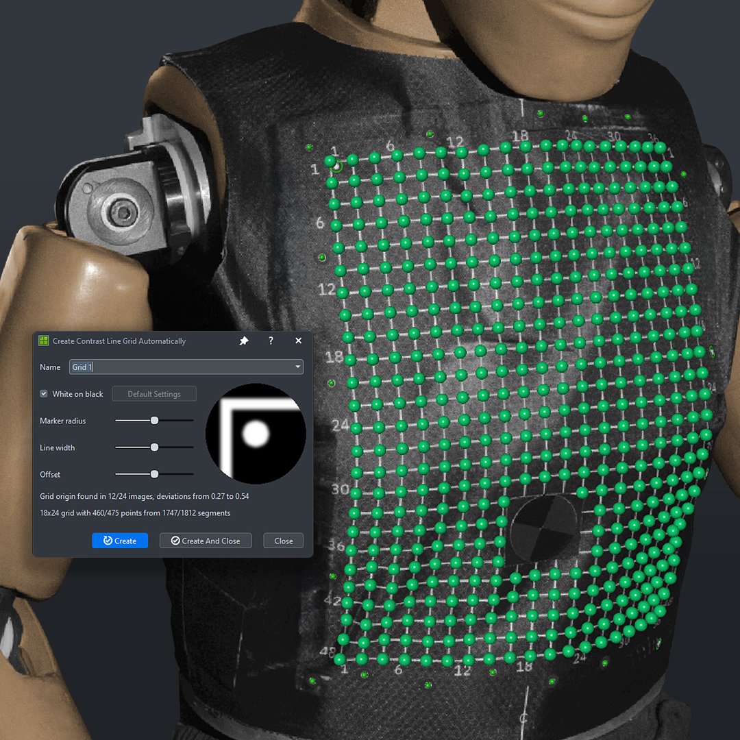
Precision electronic components mold demands +/-0.001 mm machining accuracy, verified through ZEISS or Mitutoyo-class CMM with sub-micron repeatability. XUXIANG’s ZEISS MICURA system measures to 0.7 µm, ensuring cavity dimensions, pin locations and core-insert fits meet design intent.
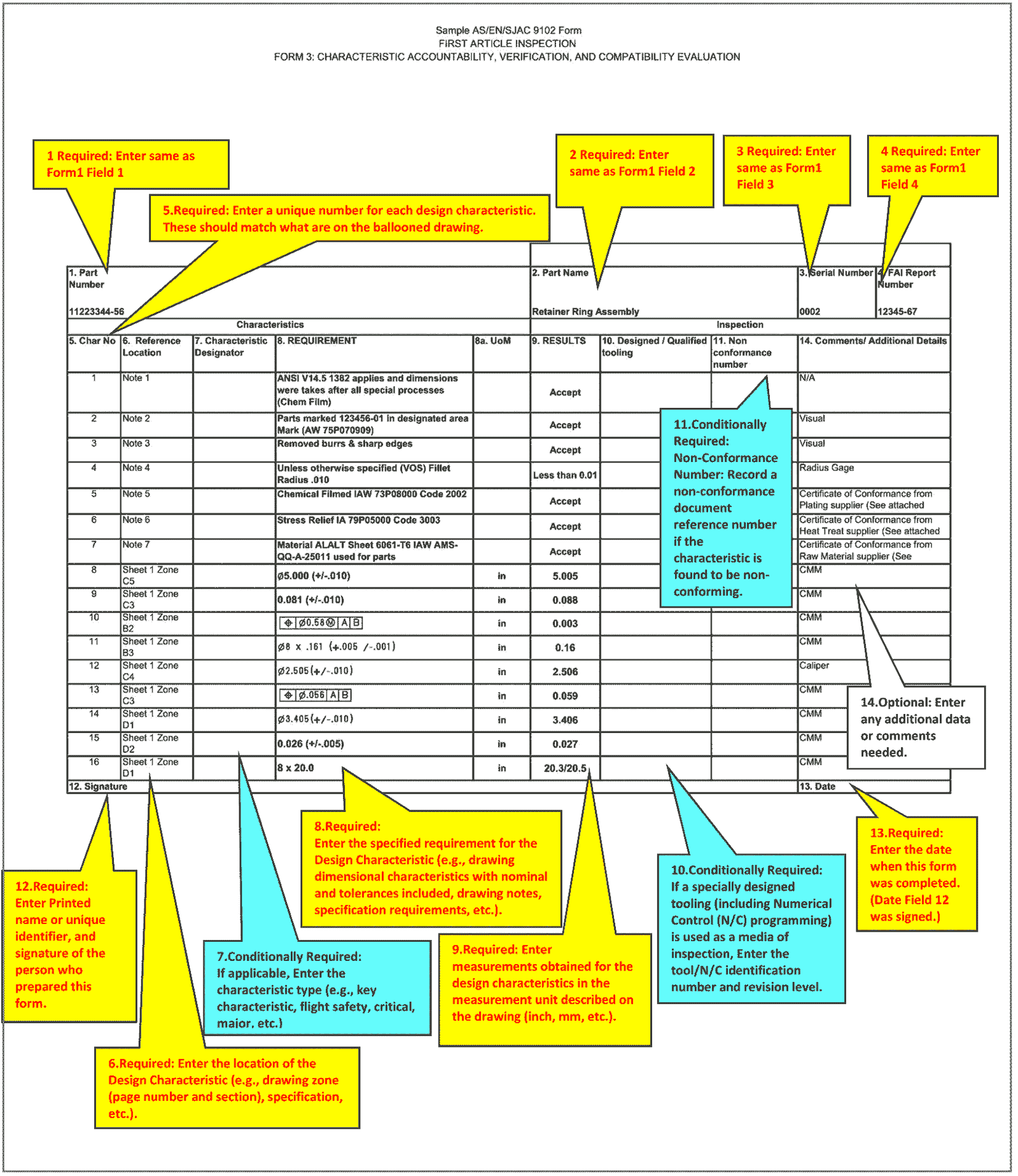
First-article inspection (FAI) captures critical dimensions on production samples, cross-referenced against CAD models. Buyers should request CMM reports showing measured vs. nominal values, tolerance zones and Cpk ≥1.67 for key features.
Surface Quality and Finish Standards
Surface roughness directly affects part release, cosmetic appearance and electrical contact reliability. Mirror-grade EDM finishes achieve Ra ≤0.1 µm on core surfaces; general cavity walls target Ra ≤0.2 µm. Optical profilometry or stylus-based measurement confirms texture compliance.
Parting-line flash control—critical for micro-connectors—requires mating surfaces ground flat within 0.002 mm and hardened to HRC 50–58. Request surface-integrity documentation including roughness charts and photomicrographs of EDM recast layers.
Cavity-to-Cavity Consistency and Repeatability
Multi-cavity electronic components mold must deliver identical dimensions across all cavities to avoid downstream sorting and scrap. Shot-to-shot repeatability testing measures part weight, critical dimensions and gate vestige over 30+ consecutive cycles.
XUXIANG’s +/-0.002 mm slow-wire EDM positioning ensures cavity symmetry. Buyers should specify acceptable cavity-to-cavity variation (typically ≤0.005 mm) and request process capability studies (Cpk) demonstrating long-term stability under production conditions.
Documentation Standards: PPAP and FAI
Automotive and medical-device supply chains require Production Part Approval Process (PPAP) packages including FAI reports, material certificates, dimensional results, process flow diagrams and control plans. ISO 9001:2015-certified shops like XUXIANG provide spectral analysis, CMM data and surface-finish records as standard deliverables.
Request FAI documentation before series production, including measured data for 100% of controlled dimensions, material traceability and signed inspection certificates. Comprehensive records reduce qualification time and support traceability audits.
7. How to Choose an Electronic Components Mold Manufacturer
Selecting the right electronic components mold partner determines whether your micro-connector or precision tooling program meets tolerance, delivery and total-cost targets. A systematic evaluation across five dimensions — certifications, technical assets, lead-time performance, cost transparency and after-sales support — separates capable suppliers from those who cannot sustain micron-stable production at scale.
Verify Quality Certifications and Compliance
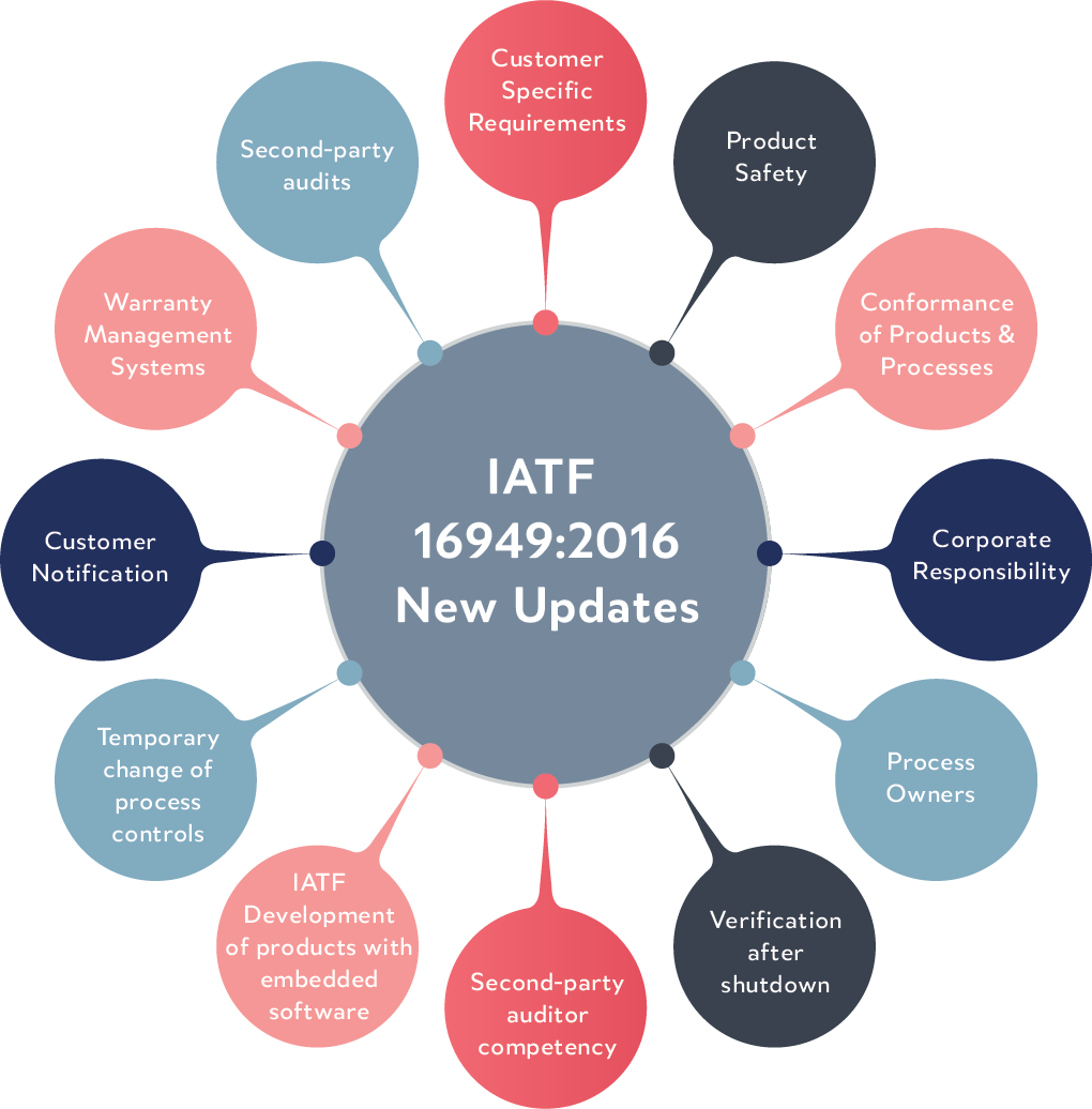
ISO 9001:2015 is the baseline; IATF 16949 is essential for automotive and NEV mold projects. Request certificate numbers and audit dates to confirm current standing. Suppliers serving medical-device or telecom OEMs should demonstrate process traceability — material certificates, FAI reports and spectral-analysis records that satisfy FDA or IPC standards.
Assess In-House Technical Capabilities
Tour the shop floor or request equipment lists: Sodick/Charmilles sinker EDM for deep-rib cores, Sodick/Seibu slow-wire EDM for +/-0.002 mm positioning, and ZEISS or Mitutoyo CMMs with sub-micron resolution. XUXIANG’s ZEISS MICURA measures to 0.7 µm, ensuring every electronic components mold insert meets print. Confirm electrode-fabrication CNC (e.g., Beijing Jingdiao) and precision grinding centers are on-site, not subcontracted.
Evaluate Lead Time and NRE Transparency
Ask for typical mold-fabrication cycles: 3–5 weeks for simple inserts, 6–8 weeks for multi-cavity micro-connector tooling. Verify DFM turnaround — XUXIANG returns feedback within 24–48 hours from a 10+ engineer team. Request itemized NRE quotes separating design, electrode machining, EDM and trial-shot costs to avoid hidden fees.
Confirm After-Sales and Maintenance Support
Mold life for electronic components can exceed 500,000 cycles if maintained correctly. Ensure the supplier stocks spare ejector pins, core inserts and wear components, and offers rework services — polishing, re-nitriding or dimensional correction. A dedicated service contact and documented maintenance schedules prevent costly production halts.
8. Common Mistakes When Sourcing Electronic Components Mold
Sourcing an electronic components mold on price alone or without validating critical engineering steps leads to costly rework, field failures and production delays. Four pitfalls account for the majority of procurement disputes: choosing the lowest bidder without tolerance proof, skipping material and heat-treatment documentation, omitting mold-flow simulation, and launching production without pilot validation.
Price-Only Decisions Without Tolerance Validation
A quote 20–30% below market average typically signals outdated equipment or unverified machining capability. Insist on recent CMM reports showing +/-0.002 mm or tighter on representative work, equipment lists naming make and model (e.g., ZEISS, Sodick), and photographs of the metrology lab before awarding the contract.
Material Shortcuts and Missing Traceability
Substituting unapproved steel grades or skipping spectral analysis saves a supplier hours but compromises mold life and part consistency. Require mill certificates, heat-treatment logs and hardness readings (HRC) for every core and cavity insert to ensure the material meets your specification and will survive the planned cycle count.
Skipping Mold-Flow Simulation
Omitting Moldflow or Moldex3D analysis to save a few days hides weld lines, air traps and warpage risks until first article. Demand simulation reports during DFM review, especially for thin-wall connectors below 0.4 mm or multi-cavity layouts, to validate gate location and cooling balance before steel is cut.
Inadequate Pilot Testing
Launching mass production without a full pilot run under production resin, cycle time and process parameters masks tolerance drift and surface defects. Specify a minimum 100–300 shot pilot with dimensional inspection every 50 cycles, material certification and a signed-off FAI report before releasing the mold to volume manufacturing.
9. Steps to Launch Your Electronic Components Mold Project
Launching an electronic components mold project requires a structured workflow that balances engineering rigor with supply-chain realities. The following five steps translate part requirements into validated production tooling, minimizing rework and schedule risk.
Define Part Specifications and Volume
Document part geometry, material grade, dimensional tolerances (+/-0.01 mm or tighter), surface finish (Ra values) and annual volume in a single specification sheet. Include functional constraints such as mating-interface clearances, ejection draft angles and anticipated cavity count. Clear specifications reduce quoting ambiguity and enable accurate DFM analysis.
Issue RFQ with CAD and Tolerance Requirements
Attach STEP or IGES 3D CAD files, 2D drawings with GD&T callouts and a tolerance matrix to your request for quotation. Specify inspection requirements (CMM, optical) and delivery milestones. A complete RFQ package shortens lead time by roughly 15–20 percent.
Review DFM Feedback and Mold-Flow Reports
Evaluate the supplier’s design-for-manufacturability recommendations on gate location, cooling channels and draft angles. Request mold-flow simulation data showing fill time, weld lines and shrinkage predictions. XUXIANG’s 10+ engineering experts provide DFM feedback before production starts.
Approve T1 Samples and Conduct FAI
Inspect first-article samples against the tolerance matrix using CMM reports, material certificates and surface-finish measurements. Conduct a formal first-article inspection (FAI) to lock dimensional baselines. Approval triggers production-run scheduling.
Ramp to Production with Preventive Maintenance
Establish a preventive maintenance schedule for cleaning, lubrication and wear inspection every 50,000–100,000 shots. Monitor cycle time and reject rates weekly. Scheduled maintenance extends electronic components mold life by 30–40 percent and protects part consistency.
10. Pricing and Cost Structure for Electronic Components Mold
Electronic components mold pricing spans USD 3,000 for single-cavity prototype tooling to USD 45,000+ for progressive stamping dies, driven by four principal cost levers: steel grade (P20 vs. H13 vs. S136), cavity count, tolerance class (+/-0.005 mm general vs. +/-0.001 mm precision), and surface finish (standard EDM vs. mirror Ra 0.1 µm). A 4-cavity production mold in NAK80 with +/-0.002 mm positioning and Ra 0.2 µm mirror finish typically costs USD 12,000–18,000 and requires 6–8 weeks, while an 8-cavity high-volume tool in hardened H13 with conformal cooling channels can reach USD 25,000–35,000 over 8–10 weeks.
Lead time correlates directly with tolerance: +/-0.001 mm class work demands ZEISS CMM validation, electrode pre-grinding and multi-pass slow-wire EDM, adding 1–2 weeks versus standard tooling. Tool life ranges from 100,000 shots for prototype-grade aluminum to 1,000,000+ shots for hardened steel progressive dies. XUXIANG’s DFM review identifies cost-reduction opportunities—relaxing non-critical tolerances, optimizing parting lines and consolidating cavities—before NRE is committed.
| Tooling Type | NRE Cost (USD) | Lead Time (Weeks) | Tool Life (Shots) |
|---|---|---|---|
| Single-Cavity Prototype (Aluminum) | 3,000–6,000 | 3–4 | 100,000–300,000 |
| 4-Cavity Production Mold (NAK80) | 12,000–18,000 | 6–8 | 500,000–800,000 |
| 8-Cavity High-Volume Mold (H13) | 25,000–35,000 | 8–10 | 800,000–1,200,000 |
| Progressive Stamping Die (Hardened Steel) | 35,000–50,000 | 10–12 | 1,000,000+ |
Get Your Electronic Components Mold Quote in 24 Hours
±0.001 mm precision, ISO 9001:2015 certified, DFM engineering support, and full FAI documentation with every shipment. Partner with XUXIANG today.