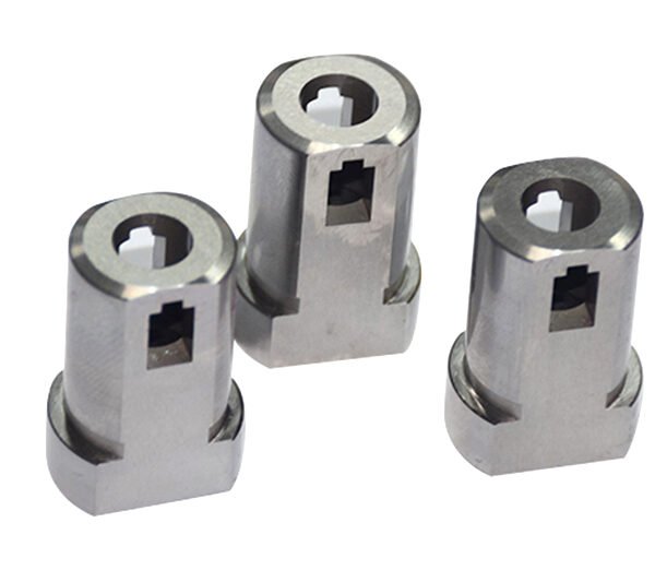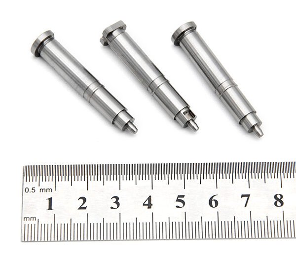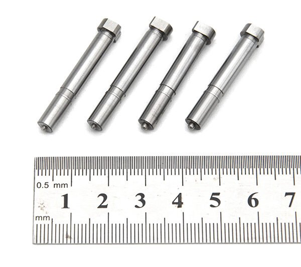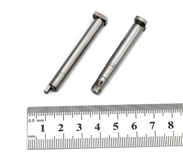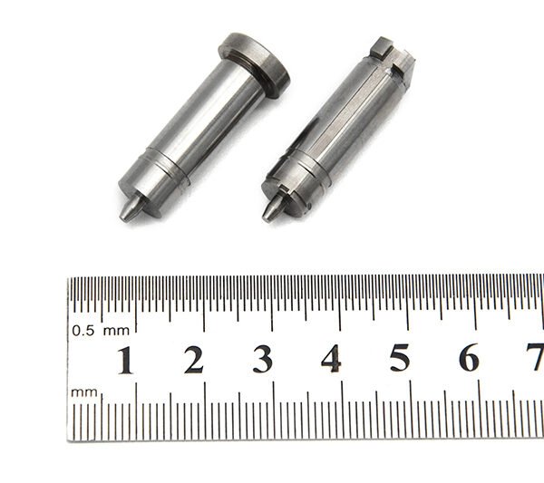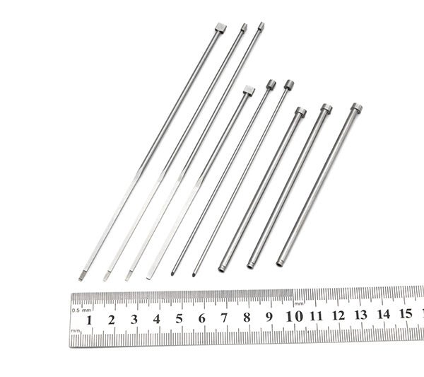
An ejector pin witness mark should be accepted or rejected against a drawing-defined location, height or depth, appearance zone and functional requirement—not by the vague instruction “no ejector marks.” Ejection necessarily transfers force to the molded part. The engineering task is to place, size and control that evidence so it does not impair sealing, assembly, appearance or safety.
This workflow supports projects using precision ejector pins and connects tool construction, molding conditions and part inspection. Final limits must come from the product drawing and customer approval.
Define the Witness Mark
An ejector witness can appear as a circular or shaped outline, raised pad, depression, gloss difference, whitening, drag, crack or local deformation. Record the actual condition and location. Do not combine every ejection defect under one label.
Identify:
- part number, revision, cavity and shot;
- ejector number and tool location;
- surface classification;
- mark diameter or geometry;
- height, depth or step;
- gloss, color and texture difference;
- associated stress, crack or deformation;
- molding cycle and material lot.
Map part evidence back to the mold layout. Cavity-specific or pin-specific trends become visible only when traceability is preserved.
Classify the Part Surface
Divide surfaces by function and visibility. A mark hidden inside a non-contact rib may have a wider visual allowance than one on a cosmetic face, optical path, gasket land, electrical interface or sliding surface.
The drawing should identify zones such as:
- Class A customer-visible surface;
- secondary visible surface;
- hidden nonfunctional surface;
- assembly or datum surface;
- seal, bond or weld interface;
- regulated or safety-critical area.
Do not place acceptance solely in an email. Link the zone map and limit to the controlled drawing, quality specification or signed appearance standard.
Specify Measurable Limits
Where function requires it, define allowable pin witness height or depth relative to a stated datum. Include measurement method, instrument, fixture, point density and uncertainty appropriate to the tolerance.
Visual requirements may need a physical master showing acceptable outline, gloss and texture. Photographs help identify location but lighting can conceal or exaggerate a mark. Define viewing distance, angle, illumination and inspection time where appearance is critical.
If “flush” is required, state a numeric or functional interpretation. Perfectly zero step is not a useful production instruction without measurement capability and an agreed tolerance.
Review Ejector Placement During Design
Place ejectors where the part can carry the ejection load and where evidence is least harmful. Consider part stiffness, draft, ribs, bosses, wall thickness, texture, undercuts and expected adhesion to core surfaces.
Avoid small pins carrying disproportionate force. Use enough ejector area and balanced distribution to prevent whitening, indentation or bending. Ensure pins do not interfere with cooling, slides, lifters, inserts or critical features.
The Krevera guide on reading ejector pin marks explains that witness patterns can reveal load and ejection behavior. Design review should therefore treat pin locations as both mechanical and quality decisions.
Control Pin Fit and Face Condition
Inspect ejector diameter, clearance, straightness, hardness, face geometry and surface finish against tool specifications. The pin face should match the intended local contour where required. A pin that sits proud or recessed can directly reproduce a step.
Check for:
- incorrect pin length;
- thermal expansion effects;
- worn guide or bore clearance;
- contamination behind the pin;
- burrs or damaged face edges;
- pin rotation where orientation matters;
- poor return or incomplete seating;
- lubrication contamination near the cavity.
Do not hand-stone a critical pin face without recording the change. Local work can alter length, edge and surface replication.
Stabilize Molding Before Correcting Steel
Witness severity can change with packing pressure, mold temperature, material temperature, cooling time, ejection speed and part adhesion. Establish a stable process window before modifying the tool.
If the part ejects while too warm, pins may indent or distort it. Excessive packing can increase core grip. Insufficient draft, rough core surfaces or vacuum can raise ejection force. However, process changes must remain within part dimensional and material requirements; reducing packing solely to hide a witness may create sink, short shot or weak dimensions.
Nanomold Coating’s discussion of ejector pin mark causes describes the interaction among ejection force, cooling and tool surface. Use such factors as investigation paths, then validate with controlled trials.
Measure Ejection Evidence Systematically
Create a sampling map by cavity and ejector location. Measure parts only after the defined conditioning interval because shrinkage and warpage can change the local step.
Possible methods include:
- contact height measurement on robust surfaces;
- optical profilometry for delicate texture;
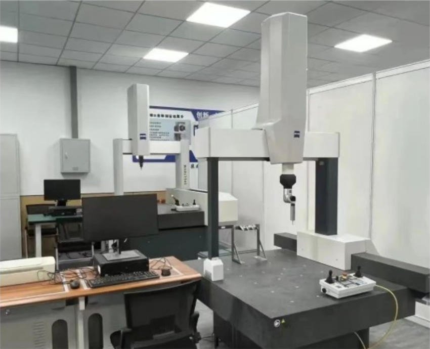
- CMM scanning with suitable probe access;
- comparison microscope or controlled photography;
- fixture-based flush or assembly checks;
- pressure film or force monitoring during development.
The chosen method must be capable of resolving the acceptance limit. Do not use a low-resolution caliper to claim a very small local surface step.
Repeatability studies should include operators, fixtures and part placement. Preserve raw readings rather than only pass/fail labels.
Distinguish Proud, Recessed and Damaged Conditions
Proud Witness
A raised area may indicate a recessed pin face in the mold, local material flow or deformation. Confirm mold-versus-part direction carefully before correcting steel.
Recessed Witness
A depression may result from a proud pin, warm ejection or high local force. Compare early and fully conditioned parts.
White or Glossy Halo
Stress whitening or gloss change can indicate local strain, texture interruption or surface drag even when height passes.
Cracking or Punch-Through
This is a structural failure, not a cosmetic witness. Stop and investigate pin area, part thickness, temperature, force distribution and material condition.
Drag Around the Pin
Check pin clearance, return, face edge, part movement and ejection alignment. Wear debris or scoring requires maintenance review.
Run Controlled Correction Trials
Change one principal variable at a time and identify every shot. A trial matrix can compare cooling time, ejection speed, mold release behavior or pin configuration while holding the rest of the validated process stable.
For tool correction, document:
- affected ejector and cavity;
- measured pre-correction condition;
- proposed face, length, diameter or distribution change;
- expected impact on ejection and appearance;
- approval authority;
- post-correction steel and molded-part evidence.
Do not polish or plate a core surface casually to reduce grip; the change may alter dimensions, texture or future maintenance.
Validate Function Beyond Appearance
Even an invisible witness can affect flatness, sealing, adhesive bond, coating, ultrasonic welding or assembly. Test the actual downstream operation.
Check whether the witness:
- contacts a mating part;
- changes datum seating;
- creates a leak path;
- disrupts label or adhesive contact;
- concentrates stress;
- interferes with automated handling;
- remains visible after coating or decoration.
If a downstream process removes or covers the mark, confirm that it does so consistently and does not introduce another defect.
Approve Across the Process Window
A golden sample from one ideal shot does not prove production capability. Mold at validated window limits and sample every cavity. Include startup, steady-state and restart conditions when relevant.
Review:
- dimensional and visual witness limits;
- part release reliability;
- ejection force trend if monitored;
- pin return and tool temperature;
- cycle stability;
- wear after an appropriate run length.
Retain cavity-identified samples and the measurement report. Define reaction rules for drift.
Production Inspection Plan
The control plan should state:
- critical ejector locations and zone class;
- measurement or visual method;
- sample frequency by cavity and lot;
- conditioning interval;
- physical master or numeric limit;
- lighting and viewing condition;
- maintenance trigger;
- containment and escalation action.
Inspect after ejector maintenance, pin replacement, process deviation or material change. Replacement pins must be qualified against the same face and length controls.
Common Approval Mistakes
Writing “no pin marks.” The instruction lacks location, limit and method.
Correcting steel before stabilizing the process. The tool may be changed for a temporary molding condition.
Checking one cavity. Load and fit can differ across the mold.
Measuring immediately after ejection. Warm deformation may not represent the conditioned part.
Approving height but ignoring whitening. Appearance and structural stress can still fail.
Reducing packing only to hide the mark. Other dimensional or performance requirements may be lost.
Frequently Asked Questions
What causes ejector pin marks?
Common contributors include high local ejection force, uneven load distribution, warm parts, excessive core grip, pin-face mismatch, incorrect pin position, wear and unstable molding conditions.
Are ejector pin marks always defects?
No. A controlled witness on an approved noncritical surface may be acceptable. The drawing and functional requirements determine the decision.
Should an ejector pin be perfectly flush?
It should meet the specified relationship to the cavity or core surface. Define a measurable limit and account for contour, temperature and inspection capability.
Can more cooling eliminate a witness?
It may reduce warm-part indentation, but it can increase cycle time and does not correct poor pin placement or force distribution. Validate the full process.
Final Acceptance Principle
Treat ejector witness marks as controlled evidence of a necessary mechanical action. A clear zone map, measurable limit, stable process, cavity traceability and functional validation allow the team to distinguish an acceptable witness from a tool or molding defect requiring correction.