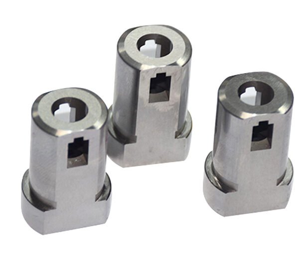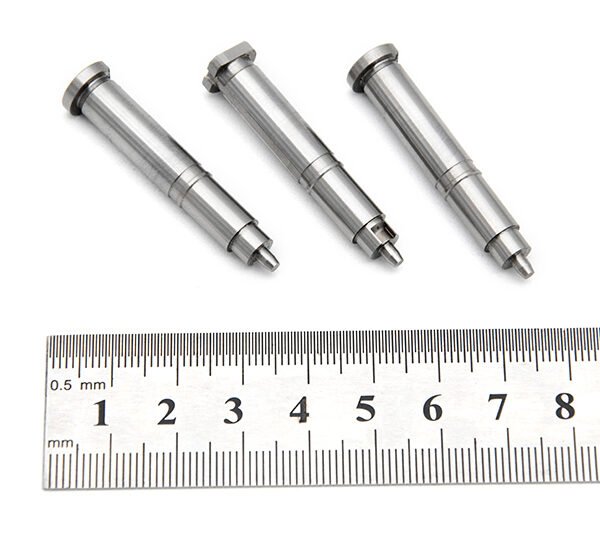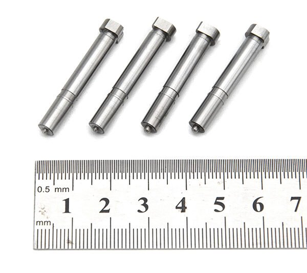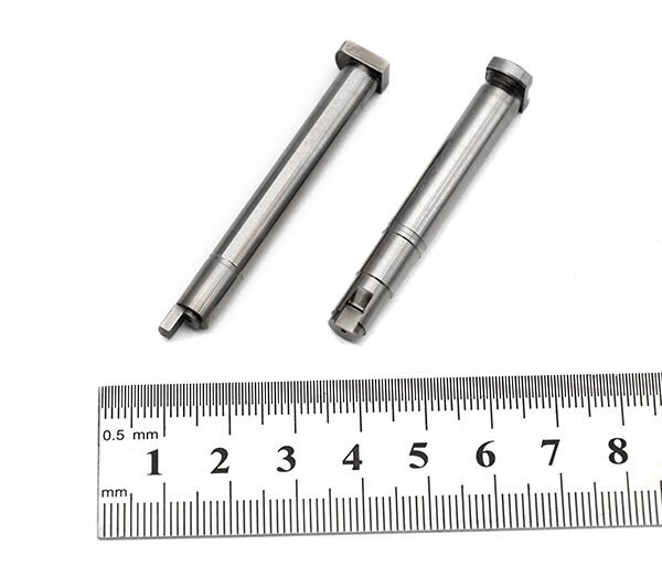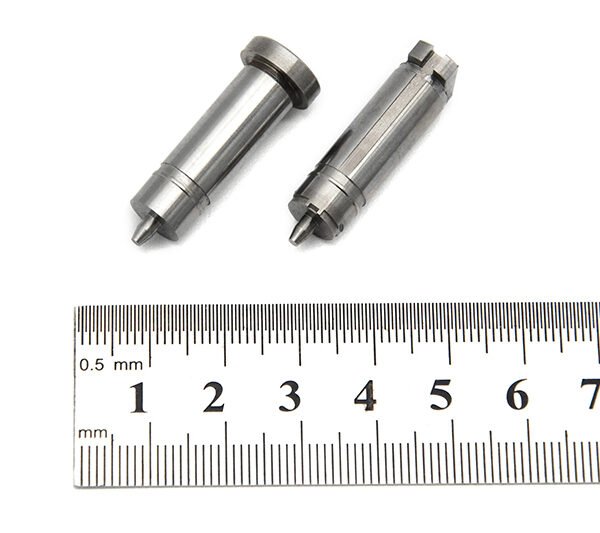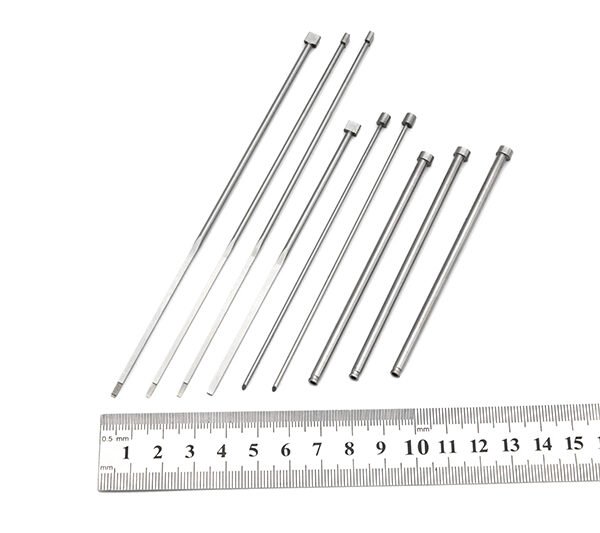
Gage R&R for precision mold components is a structured way to determine whether observed dimensional differences mostly reflect the components or the measurement process. It separates short-term measurement variation into repeatability and reproducibility, then helps buyers decide whether an inspection method is fit to support a specific acceptance decision.
The study applies to a defined measurement process and characteristic. It does not certify a component, machine or supplier.
What gage R&R means in a mold-component approval
A gage is the measurement system used for a characteristic. It may include a CMM program, probe configuration, fixture, datum setup, vision system, micrometer, software settings, work instructions, and the person or automated sequence that runs the measurement.
Gage R&R examines variation introduced while measuring. Its two measurement components are considered alongside part variation:
- Repeatability: variation when the same measurement process repeats under the same defined conditions. It is the basic precision of the gage or process, not proof that the reported value is correct. NIST describes repeatability as quantifying basic precision and notes that repeatability can be assessed across relevant conditions when pooling is appropriate. NIST: Analysis of repeatability
- Reproducibility: variation associated with meaningful changes in the measurement process, often different operators using the same approved method. It can also be investigated across other deliberate conditions when those conditions are part of normal use.
- Part variation: real difference among the components selected for the study. This is not measurement error. In a useful study, it gives the method something real to distinguish.
For a precision mold component, these distinctions matter because a reported difference may arise from probe access, contact force, fixture seating, a datum interpretation, surface condition, feature form, CMM alignment, or a genuinely different part. A gage R&R study is designed to reveal which explanation deserves attention.
NIST frames gauge studies as measurement-process characterization that can address repeatability, reproducibility, stability, bias, resolution, linearity, hysteresis, drift, and differences among gauges or configurations. That scope is a useful reminder that R&R is important but not the whole measurement-system question. NIST: Gauge R & R studies
Terms buyers should keep separate
Several terms are routinely bundled together as “measurement capability.” They should not be treated as interchangeable.
Precision means closeness among repeated readings. A highly precise process can repeatedly report the wrong result.
Bias or accuracy concerns closeness to an accepted reference or true value. Bias is directional error; accuracy is a broader practical idea that includes both systematic and random effects. Calibration evidence may be relevant to bias, but calibration alone does not show how a complex part, fixture, program, or routine behaves in production.
Resolution is the smallest reporting increment or discernible change of the system. Fine display resolution does not guarantee low measurement variation, correct datum construction, or sufficient sensitivity on the actual geometry.
Calibration establishes the relationship between an instrument’s indications and reference values under specified conditions. It supports traceability; adjustment is a separate operation. It does not replace a study of the full method used on a mold component.
Stability concerns whether performance remains consistent over time. A short study can be repeatable today while the process changes later because of wear, environment, programming, service activity, or other causes.
Full measurement uncertainty is broader than short-term R&R. NIST cautions that a gauge study can support uncertainty assessment only when it is representative of the working measurement process, and that errors absent from a short-term run or changes over time must still be considered. NIST: Quantifying uncertainties from a gauge study
Start with the characteristic and the real measurement method
A study is only as useful as the process it represents. The buyer and inspection team should agree on the exact characteristic before values are collected. “Check the part on the CMM” is too broad.
Specify the drawing revision, dimension or geometric control, units, nominal and tolerance, datum scheme, reporting convention, measurement path, probe or sensor configuration, filtering where applicable, and the approved fixture. For features affected by temperature, cleaning, burr condition, or part orientation, state the normal handling conditions. The study must represent the process actually used for acceptance.
A repeated CMM execution with the part left clamped and alignment retained is useful diagnostic evidence, but it is narrow. It mainly tests the repeatability of that retained setup. If normal inspection involves unloading, reloading, locating against a fixture, rebuilding an alignment, or selecting datum contact points, the representative study should include those steps. Otherwise, it can understate variation relevant to incoming or final inspection.
Likewise, an automated routine need not have operator-to-operator differences if operators do not materially change the workflow. Do not manufacture an appraiser factor merely because a textbook example contains one. Instead, include the actual sources of variation: loading method, fixture station, program selection, configuration, shift, or any other normal condition that can change the result.
For an individual component result, the companion question is whether the report clearly identifies the feature, datum interpretation, equipment, and result. Buyers reviewing reports can use this guide to reading a CMM inspection report alongside an R&R discussion.
Choose a study design that matches the parts
A crossed study is appropriate when each selected, stable part can be measured repeatedly by every relevant operator or condition. It allows the study to distinguish variation associated with parts from variation associated with repeat measurements and, where relevant, appraisers.
A crossed design is not automatically appropriate. If measurement is destructive, permanently alters the sample, or the same physical part cannot practically be remeasured, ask the metrology owner for a suitable nested or destructive-study design. In those designs, the structure and assumptions differ because each operator or trial may receive different specimens. Treating unlike parts as though they were the same part creates a deceptively tidy but invalid result.
Part selection deserves as much scrutiny as software output. Select components that represent the actual approval or production decision and show a realistic spread of the characteristic. Avoid a set made only of nearly identical parts, because the study may not reveal whether the system can distinguish meaningful differences. Avoid deliberately selecting only extremes, because that can make a method look more discriminating than it will be in normal use. Include the relevant part family, geometry, surface state, and manufacturing route when they influence measurement.
There is no universal sample-count promise that makes a study valid. The suitable number of parts, trials, operators or conditions depends on the risk, feature behavior, available stable samples, intended analysis, and normal measurement workflow. A documented rationale is more credible than a copied template.
A numbered workflow for approving a gage R&R study
- Define the decision at risk. State whether the measurement will support first-article approval, in-process adjustment, final acceptance, supplier comparison, or investigation of a disputed result. A method adequate for a broad noncritical dimension may be inadequate for a datum-sensitive feature.
- Freeze the measurement definition. Agree the characteristic, drawing revision, normal method, datum strategy, fixture, program version, equipment configuration, reporting rule, environmental controls that are actually used, and the condition of the part before measurement.
- Select representative parts. Use stable components spanning a realistic and useful range without cherry-picking nearly identical pieces or an artificial collection of extremes. Record why the set represents the decision.
- Set the study design. Use a crossed design only when every relevant operator or condition can measure the same stable parts repeatedly. For destructive or non-repeatable situations, agree an appropriate nested design before collection.
- Define participants, trials, and randomization. Identify meaningful operators or process conditions, the planned repeats, blinding or coding where useful, and a randomized order for every measurement cycle. Participants should follow the normal approved work method, not a special demonstration method.
- Collect raw data without cleanup. Preserve individual readings, part IDs, operator or condition IDs, trial order, equipment and program information, and deviations from plan. A suspect value is a finding to investigate, not an inconvenience to delete.
- Review the variation pattern before deciding. Look beyond one headline percentage. Compare repeatability, reproducibility when applicable, part-to-part separation, condition effects, and visible interactions. Ask whether the raw pattern makes engineering sense for the feature and setup.
- Investigate the dominant cause and improve deliberately. High repeatability variation can point toward instrument, probing, fixture, surface-contact, or setup issues. High reproducibility variation can point toward technique, datum interpretation, instruction clarity, or workflow differences. Improvement may involve instrument, fixture, or technique; document what changed.
- Rerun a controlled study after the documented change. Do not remove inconvenient readings from the original study to manufacture a better result. Keep the original evidence, establish the revised method, and show that the revised result belongs to that revised process.
- Issue an approval record with boundaries. Record the characteristic, method, design, raw-data location, analysis approach, limitations, findings, disposition, and re-evaluation triggers. This gives a buyer a usable audit trail rather than an isolated score.
How to interpret the reported percentages
Two common ways of expressing R&R use different denominators:
- Percent of study variation compares measurement variation with the observed variation in the study. It asks how much of the studied spread is associated with the measurement system.
- Percent of tolerance compares measurement variation with the drawing tolerance. It asks a different question: how much of the allowable engineering interval is consumed by measurement variation.
Neither figure is self-explanatory. A favorable percentage of study variation can result when the selected parts have a broad range, even if the measurement process is not adequate for a tight tolerance. A favorable percentage of tolerance does not prove that selected parts represent normal process behavior. Read the denominator, the part range, and the decision context before accepting either result.
Avoid universal pass/fail folklore such as a fixed “good” cutoff. Risk, feature function, tolerance, process behavior, consequences of a false accept or false reject, and the intended use of the result all matter. A buyer should ask the quality team to state the acceptance rationale rather than merely label a score green, yellow, or red.
A good R&R result also does not certify that every component meets its drawing tolerance. It supports confidence in the defined measurement process. Conformity still requires correctly measuring each applicable part or an otherwise justified inspection plan, using the approved drawing requirements and acceptance rules.
A compact review checklist for buyers
Before relying on a supplier-provided study, confirm that you can answer these questions:
- Is the characteristic tied to the correct drawing revision, tolerance, and datum approach?
- Does the tested workflow include normal loading, fixturing, alignment, and handling rather than only a retained setup?
- Are the selected parts representative and varied enough to test discrimination without artificial selection?
- Is the design crossed only where the same stable parts can actually be remeasured?
- Do the report and raw-data record identify conditions, trials, changes, exclusions, and the rationale for the conclusion?
- Does the result address the intended decision, rather than being presented as a blanket claim about all inspection or all components?
For broader inspection-process context, consult the manufacturer’s quality and inspection overview and evaluate it against the documentation required for your program.
Buyer FAQ
What is a gage repeatability and reproducibility study?
It is a measurement-system study that separates short-term variation from repeated measurement and, where relevant, variation between operators or other normal measurement conditions. Its purpose is to determine whether observed differences can be credibly attributed to components rather than measurement noise.
How do I interpret gage R&R results?
Start with the exact characteristic, denominator, part range, study design, and raw-data pattern. Then ask whether the measured workflow matches normal inspection. A single percentage without those boundaries is insufficient for an approval decision.
What is a good gage R&R score?
There is no universal score that is good for every precision mold-component application. Establish an acceptance rationale based on tolerance, feature function, risk of wrong disposition, expected part variation, and the decision the data must support.
How do you calculate repeatability and reproducibility?
Analysis software commonly partitions variation from the planned data structure. Buyers do not need to reproduce equations to evaluate the study; they should verify that the design, recorded conditions, raw data, and interpretation match the actual measurement process.
How do I measure repeatability and reproducibility on a CMM?
Define the feature, datum strategy, program, fixture, loading routine, and relevant conditions first. If unloading and reloading are normal, include them. If an automated sequence removes meaningful operator influence, study the real sources of variation instead of forcing operator differences into the design.
If you are defining an inspection plan for a precision mold component, share the drawing characteristic, datum intent, and intended acceptance decision with XUXIANG through the contact page.