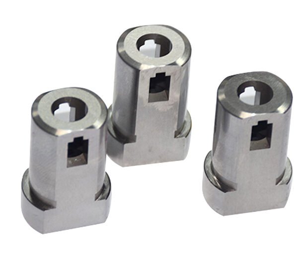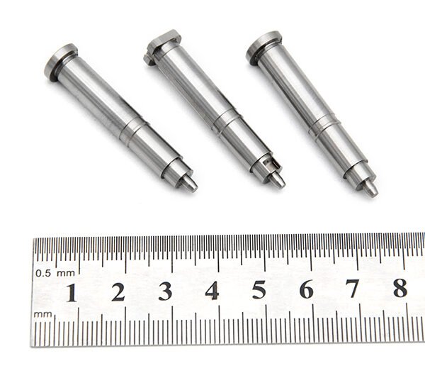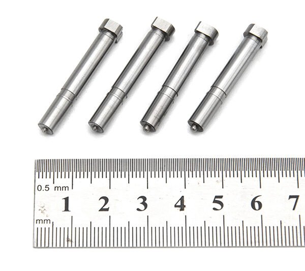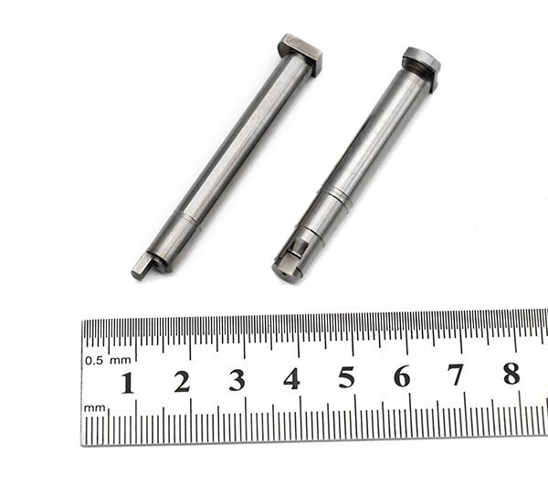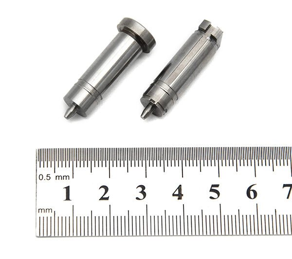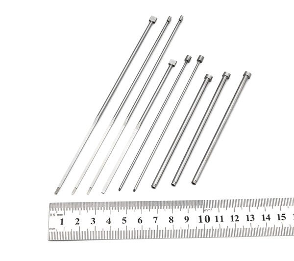
Mold guide pin and bushing clearance must allow repeatable platen-side alignment through the operating temperature range without binding, impact, excess play or abnormal wear. A nominal diameter difference alone is insufficient. Geometry, position, surface finish, hardness, lubrication, thermal growth and assembly datums determine the working fit.
This workflow supports precision guide pin and leader pin projects and connects specification, incoming inspection, assembly and maintenance evidence.
Define the Guiding Function
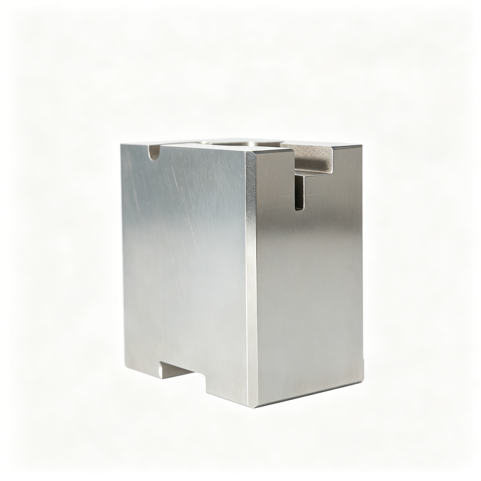
Guide pins and bushings bring mold halves into repeatable relative position during closing. They are not a substitute for every precision alignment feature or for correct machine setup. Taper locks, interlocks and cavity-specific alignment may carry separate final-location functions.
State the guide system’s role, mold size, mass, orientation, opening stroke, speed and temperature. Identify whether pins are straight, shouldered or tapered-entry and whether bushings are plain, headed, self-lubricating or another approved type.
First Mold’s overview of guide pins and guide bushings describes their basic alignment function. The engineering drawing must then define the exact component and fit for the tool.
Use Supplier Fit Data and Controlled Drawings
Select pin and bushing as a matched system from qualified data. Record nominal diameters, individual tolerances, material, hardness, coating, length and lubrication requirements.
The drawing should include:
- pin diameter and straightness;
- bushing inside and outside diameters;
- pin and bushing position datums;
- perpendicularity to parting plane;
- lead-in geometry;
- engagement length;
- bushing press fit or retention;
- surface finish;
- temperature assumptions;
- inspection method.
Do not copy a “standard clearance” without confirming component series, size, speed, load and supplier recommendation.
Calculate the Tolerance Stack
Working diametral clearance varies between the maximum and minimum limits of both parts. Calculate worst-case minimum and maximum clearance from the controlled tolerances. Include coating thickness where it affects the final diameter.
Minimum clearance must avoid binding after alignment and thermal effects. Maximum clearance must avoid excessive impact, misalignment and wear. The permissible range is an engineering decision tied to the mold system.
Keep actual measured values for assembled sets. A pass/fail result alone cannot reveal drift toward one end of the range.
Control Geometry Beyond Diameter
A pin can meet diameter but bind because it is bent, tapered unexpectedly, out of round or installed off-axis. A bushing can meet bore size but be distorted by press fit or misaligned in its seat.
Inspect:
- straightness and cylindricity;
- roundness;
- bore taper;
- pin and bore surface finish;
- perpendicularity;
- center-to-center position;
- lead-in and edge condition;
- shoulder seating;
- retaining features.
Measure the bushing after installation when press fit can change the bore. Protect measuring surfaces from dirt and temperature variation.
Establish Datums for Position
Reference pin and bushing locations to mold-base datums and parting plane. Measure center positions as a pattern, not independent isolated holes only. Relative error among four guides can cause binding even when each coordinate appears close to a local reference.
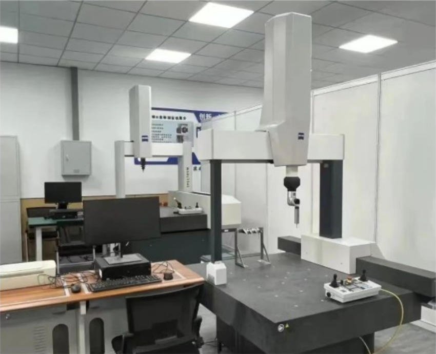
Use CMM or suitable metrology for the required accuracy. Define probing strategy, temperature and setup. For large plates, support them to avoid sag affecting results.
Control Bushing Installation
Verify housing bore, edge preparation, cleanliness and retention method. Press bushings with controlled support and alignment. Do not strike precision faces directly.
After installation, inspect seating, bore size, perpendicularity and damage. Excessive interference can close or distort the bore; insufficient retention can allow movement.
Prototool’s guide to injection mold guide bushings provides a general view of bushing function and construction. Final press-fit values should come from the component supplier and mold drawing.
Check Engagement by Assembly Stages
Before full assembly, verify each pin and bushing pair clean and lightly lubricated as specified. During trial closing, observe first contact and progressive engagement at low speed under controlled conditions.
Do not pull a misaligned mold closed with bolts or machine force. Witness marks, sudden resistance or asymmetric contact require measurement and correction.
Use spotting or indicator methods appropriate to the tool to identify contact. Preserve evidence by guide position.
Account for Thermal Growth
Mold plates, pins and bushings change dimensions and positions with temperature. Material combinations and distance between guides affect growth. Evaluate the operating range rather than room-temperature assembly only.
Run controlled heat-up trials and monitor closing behavior. Check whether lubrication, clearance and alignment remain stable. Avoid making unsupported universal thermal-clearance claims; calculate from materials and actual geometry.
Record cold and operating conditions in the qualification file.
Specify Lubrication and Cleanliness
Use the approved lubricant type, quantity and interval. Excess lubricant can attract abrasive debris or migrate toward molding surfaces; insufficient lubrication increases friction and wear.
Clean pins and bushings using compatible methods. Inspect for resin dust, metal particles, corrosion and dried grease. Do not polish precision surfaces casually; diameter and finish can change.
Self-lubricating components still require the supplier’s installation and maintenance instructions. “Maintenance-free” should not be assumed.
Measure Functional Play and Alignment
Where required, use indicators or precision fixtures to assess relative movement and repeatability. Measure at defined mold positions and support conditions.
Distinguish guide clearance from parting-line alignment. Final mold accuracy may depend on interlocks after the guide pins initiate closing. Record which feature is engaged during each measurement.
Repeat cycles to identify hysteresis, impact or inconsistent seating. A one-time smooth manual slide does not prove production behavior.
Diagnose Common Failure Patterns
Binding at Initial Entry
Check lead-in damage, gross position, mold tilt and first-contact sequence. Do not force closure.
Binding After Partial Engagement
Inspect pin straightness, bore alignment, plate parallelism, thermal condition and multi-pin position stack.
Polishing or Wear on One Side
The pattern can indicate off-axis load, misalignment or plate deflection. Map wear by guide location and direction.
Impact Marks at Bushing Mouth
Check entry alignment, machine setup, pin lead and closing speed. Repeated impact can enlarge the bore and damage edges.
Excessive Mold-Half Play
Measure pin and bushing wear and actual clearance, then inspect interlocks and other alignment features. Replace matched components under change control.
Bore Shrinks After Installation
Review housing fit, bushing wall, installation method and measurement. Reaming or honing requires an approved procedure and may affect hardness or finish.
Qualification Sequence
- approve component series and fit calculation;
- inspect incoming pins and bushings;
- measure plate bores and positions;
- install bushings using controlled fixtures;
- remeasure installed bores and seating;
- assemble and close at low speed;
- verify guide contact and final alignment features;
- cycle through operating temperature;
- inspect wear and lubricant condition;
- release the maintenance standard.
Production and Maintenance Record
Keep:
- supplier and component identifiers;
- material, hardness and coating;
- tolerance-stack calculation;
- incoming measurement report;
- plate datum and position results;
- installed bore inspection;
- assembly and heat-cycle findings;
- lubricant and cleaning procedure;
- wear maps and replacement history;
- acceptance, approver and date.
Measure replacement components and investigate the cause of abnormal wear before returning the mold to service.
Common Specification Mistakes
Defining diameter only. Position, straightness and installation can still cause binding.
Measuring the bushing before press fit only. Installation distortion is missed.
Forcing assembly closed. Damage hides the original alignment fault.
Ignoring operating temperature. A cold fit may change in production.
Using excess lubricant to mask misalignment. Wear and contamination risk increase.
Replacing one part without measuring the mate. The final clearance may remain wrong.
Frequently Asked Questions
What clearance should a mold guide pin and bushing have?
Use the matched component supplier’s fit and the mold engineering calculation. Size, material, temperature, length and system accuracy determine the range.
Why can a guide pin bind even when diameters pass?
Bent pins, bore distortion, position error, plate misalignment, inadequate lead-in, contamination and thermal growth can all cause binding.
Should bushings be measured after installation?
Yes when the housing fit can distort the bore. The installed condition is the functional condition.
Do guide pins provide final cavity alignment?
They guide mold halves, while precision interlocks or other features may control final alignment. Define the architecture for the specific tool.
Final Approval Principle
Approve guide pin and bushing clearance as a geometric and operating system. Matched tolerances, controlled datums, installed-bore inspection, low-speed engagement, temperature validation, lubrication and wear records provide alignment without binding or uncontrolled play.
Establish Replacement and Interchange Rules
Decide whether pins and bushings are replaced as matched pairs or can be replaced individually within a measured fit. Mark component location so maintenance does not exchange guides casually among positions. If orientation or coating matters, make it unmistakable on the drawing and maintenance record.
After replacement, repeat installed bore, position and low-speed engagement checks. Cycle the mold through operating temperature and inspect the new contact pattern before full-rate production. A component that slides freely on the bench may bind when combined with plate position error and thermal growth.
Set wear triggers using actual diameter, play, surface and alignment evidence. Do not wait for visible galling or a crash. Preserve removed components long enough to investigate the wear direction and source, and link findings to lubricant, cleaning, machine setup and interlock condition. This closes the maintenance loop instead of treating every replacement as an isolated event.