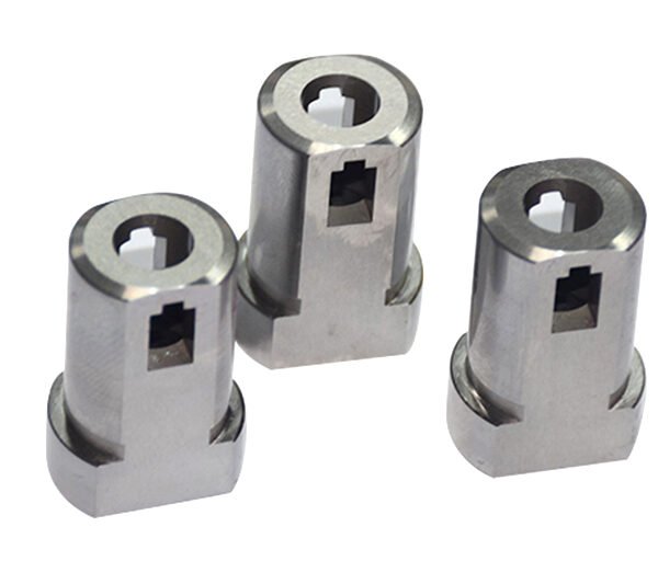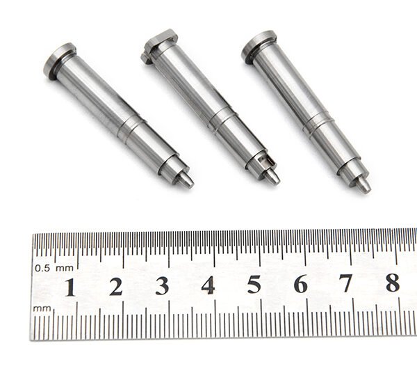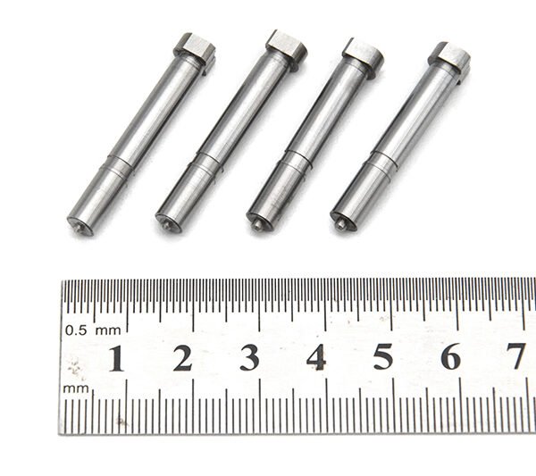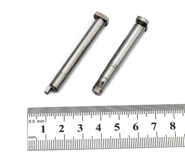
A mold insert pocket fit must locate the insert repeatably, support molding loads, allow the intended assembly method and preserve serviceability through temperature and maintenance. “Slide fit” or “tight fit” is not enough. Datums, tolerances, corner relief, seating surfaces, retention and thermal behavior must be defined together.
This workflow supports precision cavity and core mold inserts from design through replacement verification.
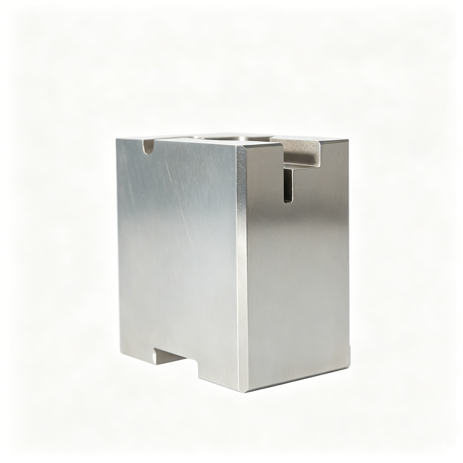
Define What the Pocket Controls
State which surfaces locate position, resist molding pressure, seal plastic, control shutoff or transfer heat. Separate locating datums from clearance surfaces and extraction features.
The drawing should identify:
- primary seating face;
- lateral and longitudinal datums;
- insert and pocket dimensions;
- corner radii and relief;
- bottom clearance where intended;
- side clearance or interference;
- retention screws, keys or wedges;
- coolant or vent interfaces;
- removal and replacement direction.
Do not allow an uncontrolled surface to become the first point of contact.
Build the Tolerance Stack
Calculate worst-case fit from insert and pocket limits, coatings, heat treatment movement and finishing stock. Include position and form, not diameter or width alone.
The minimum condition must assemble without damaging the insert; the maximum must maintain location and load support. Functional requirements determine the range.
Fictiv’s overview of injection molding tolerances explains how material, geometry and process affect achievable dimensions. Tool-component fits require a separate precision stack tied to manufacturing and inspection capability.
Establish a Datum Strategy
Reference insert and pocket measurements to corresponding datums. Use a primary seating plane and secondary and tertiary location features that constrain the required degrees of freedom.
Avoid redundant overconstraint unless deliberately engineered. Multiple competing side contacts can bind as temperature changes.
Show datum targets, measurement setup and assembly orientation. Replacement suppliers must reproduce the same functional references.
Control Geometry, Not Just Size
Inspect flatness, parallelism, perpendicularity, straightness and position. An insert can meet width yet rock on a bowed seat or bind in a tapered pocket.
Check:
- seating-face flatness;
- pocket-floor flatness;
- wall perpendicularity;
- opposite-wall parallelism;
- insert squareness;
- corner radius compatibility;
- edge burrs;
- surface finish;
- coating buildup.
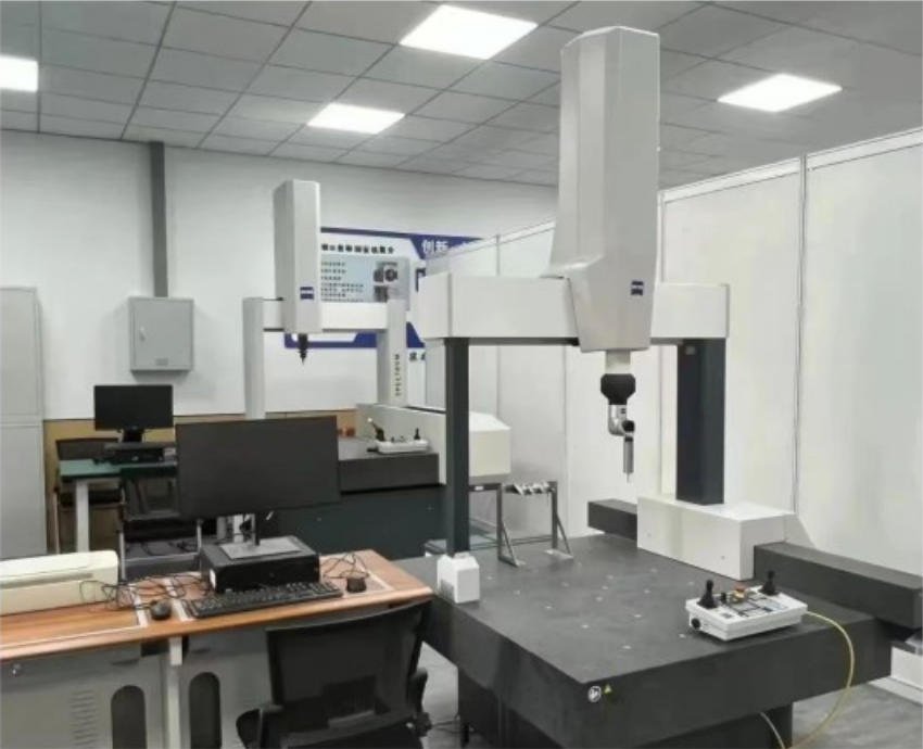
Use metrology appropriate to the tolerance. Support large components to prevent measurement sag.
Provide Corner and Tool Relief
Internal pocket corners have radii; insert corners need compatible radius, chamfer or relief. A sharp modeled corner that cannot be machined creates unintended contact.
Define relief so the insert seats on intended planes without weakening a critical edge. Inspect for burrs and residual material after milling or EDM.
Witness compound or controlled spotting can reveal high contact, but use methods compatible with surface and cleanliness requirements.
Verify Seating Contact
The insert should seat fully and repeatably against the primary face. Measure height or flushness relative to mold datums after assembly.
Use controlled torque and fastening sequence for retention. If tightening changes seating height, investigate rocking, debris, screw pull or uneven contact.
Do not draw the insert into an undersized or misaligned pocket with screws. This can distort parts, damage threads and hide the original fit.
Design Retention Separately From Location
Screws, clamps, keys, wedges or backing plates hold the insert under operating loads. Location surfaces position it. Do not rely on fastener clearance holes as precision datums unless designed for that function.
Calculate loads and choose retention under the tool design requirements. Record fastener grade, thread engagement, torque procedure and locking method.
Ensure removal features do not damage cosmetic or sealing surfaces. Provide jack screws, puller threads or access where appropriate.
Account for Thermal Behavior
Insert and mold base materials may expand differently. Size, temperature, distance from the thermal center and cooling layout affect fit.
Evaluate cold assembly and operating temperature. Confirm that the insert does not bind, lift or lose contact. Do not use a universal thermal allowance without calculation.
Record mold temperature during qualification and compare height or witness patterns after cycling.
Protect Cooling, Venting and Sealing Interfaces
Where the insert includes cooling channels or O-rings, verify port alignment, seal compression and leak testing. Pocket fit must not cut or extrude seals.
For vents, confirm seating and side fit preserve the designed path. Uncontrolled gaps can flash; blocked gaps can trap gas.
Shutoff and parting surfaces need their own contact and spotting acceptance. A general pocket clearance does not define plastic sealing.
Inspect Assembly Cleanliness
Clean pocket, insert, fasteners and cooling interfaces before assembly. A small chip can hold the insert high and create part flash or dimension shift.
Document approved cleaning and rust-prevention materials. Excess grease can hydro-lock a blind pocket or contaminate molding surfaces.
Inspect after trial removal for fretting, scoring, corrosion and trapped debris. Map marks to identify unwanted contact.
Run Molded-Part Validation
After assembly, mold under the validated process and inspect cavity-specific dimensions, flash, appearance and function. Compare insert height and part evidence across heat-up and steady production.
Super Ingenuity’s insert case studies on shutoff fit and wear zones reflect how insert fitting affects molded outcomes. Final acceptance should connect tool measurements to actual parts.
If part dimensions drift after insert removal and reinstallation, investigate datum repeatability, debris, torque and seating.
Qualify Replacement Inserts
Replacement control is a central reason to define datums and fit clearly. Manufacture the spare to the same controlled drawing and inspect it independently.
Before production release:
- verify material, heat treatment and coating;
- inspect functional dimensions and geometry;
- clean and trial assemble without force;
- measure installed height and location;
- pressure-test cooling where relevant;
- cycle at operating temperature;
- mold and inspect parts;
- record the change and retained samples.
Do not hand-fit a spare without updating its actual dimensions and interchangeability status.
Diagnose Common Failures
Insert Will Not Seat Fully
Check debris, corner interference, taper, burrs, pocket geometry and datum conflict. Do not increase screw force.
Insert Rocks in the Pocket
Inspect seating flatness, high spots, retention sequence and pocket floor. Map contact.
Installed Height Changes With Torque
Review rocking, fastener pull direction, bottom clearance and seating contact.
Fretting Appears on One Wall
Check operating load, thermal growth, location, retention and mold-base deflection.
Flash Appears Around the Insert
Inspect shutoff or parting contact, seating height, damage, process pressure and thermal condition.
Spare Fits Differently
Compare datum method, coating, heat-treatment movement, actual pocket condition and undocumented hand fitting.
Inspection and Maintenance Record
Keep:
- controlled drawing and fit calculation;
- insert and pocket measurement reports;
- datum and seating maps;
- material, heat treatment and coating;
- retention and torque procedure;
- thermal and cooling validation;
- molded-part evidence;
- removal, wear and repair history;
- spare interchangeability status;
- approver and date.
Common Specification Mistakes
Writing “fit to pocket.” No dimensions, datums or method are defined.
Measuring size but not flatness. The insert can rock or bind.
Using screws to pull the insert into place. Damage and distortion are hidden.
Ignoring internal corner radii. Unintended contact prevents seating.
Qualifying cold only. Thermal behavior remains unknown.
Hand-fitting a spare without records. Interchangeability is lost.
Frequently Asked Questions
Should a mold insert be press fit?
Some designs use interference while others use controlled clearance and retention. Choose from load, temperature, service and accuracy requirements.
What causes an insert to sit proud?
Debris, corner interference, pocket or insert geometry, rocking, coating buildup and fastener pull can contribute.
Why separate location and retention?
Datum surfaces position the insert; fasteners hold it against operating loads. Combining those roles unintentionally reduces repeatability.
How is a replacement insert approved?
Inspect it to the same datums, trial assemble, verify height and systems, cycle thermally and validate molded parts.
Final Approval Principle
Approve insert pocket fit as a located, seated, retained and serviceable system. Controlled datums, geometric inspection, thermal validation, molded evidence and replacement records make precision repeatable beyond the first hand-fitted component.
Verify Alignment With Adjacent Inserts
Multi-insert cavities introduce another tolerance relationship. Map each insert’s datums, gaps, shutoffs and surface transitions. An individual insert can seat correctly yet create a visible step or flash line relative to its neighbor.
Measure assembled height and position as a group. Use cavity identifiers and record the installed orientation. If inserts are exchanged among pockets, qualify that interchange explicitly; otherwise preserve dedicated pairings.
During spotting, distinguish pocket seating from insert-to-insert contact. Do not stone a cosmetic transition before proving both components sit on their intended primary planes.
Control Weld Repair and Surface Restoration
Welding, coating, polishing and texture repair can change insert size, flatness and corner relief. Treat every repair as a fit-affecting change. Inspect the component before and after heat treatment or finishing and recalculate the critical stack when material is added.
After repair, trial assemble without force, measure installed height and revalidate cooling, venting and molded appearance. Preserve photographs of the repaired zone. If hand fitting is necessary, record actual final dimensions and update whether the insert remains interchangeable.
Establish Removal and Storage Procedures
Specify the removal tool, jack-screw sequence and protected contact points. Technicians should not pry against cavity edges or sealing surfaces. Inspect the empty pocket and removed insert for fretting, corrosion, debris and raised burrs.
Clean and protect both parts with approved materials, then store inserts by cavity and orientation in a labeled container. Before reinstalling a stored insert, inspect preservation residue and repeat seating checks. Controlled removal prevents maintenance from gradually destroying the fit established during toolmaking.