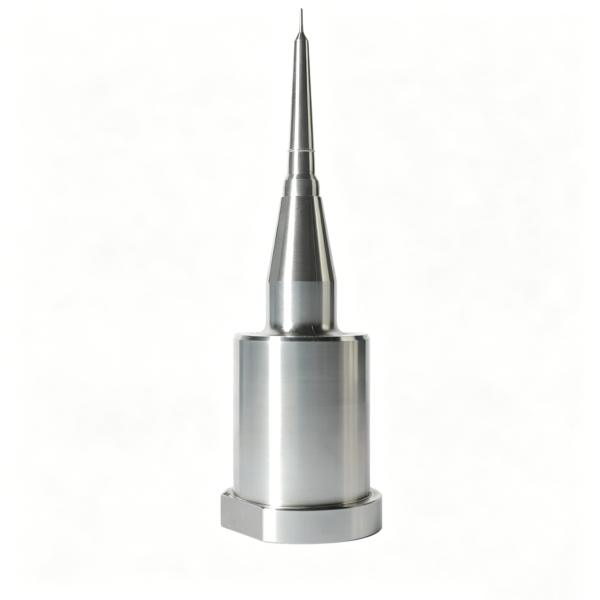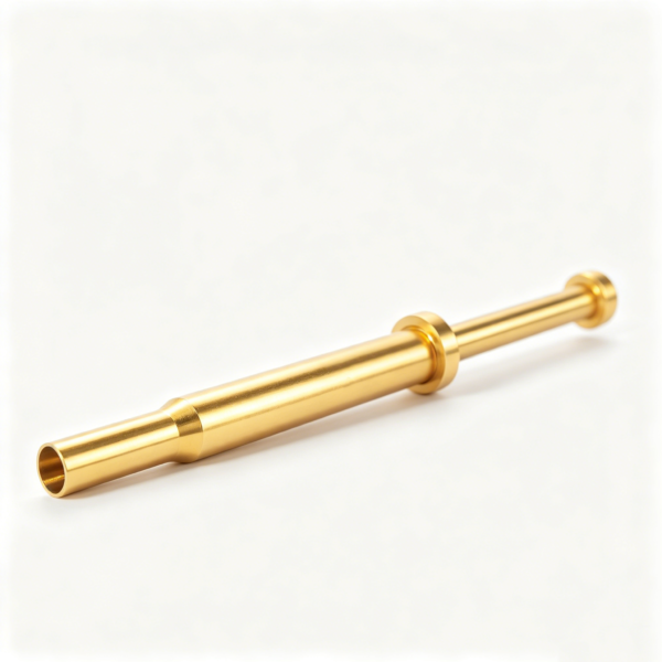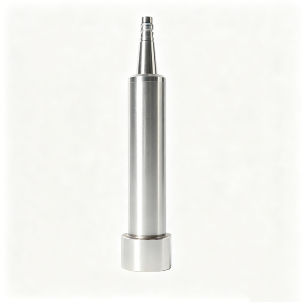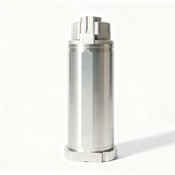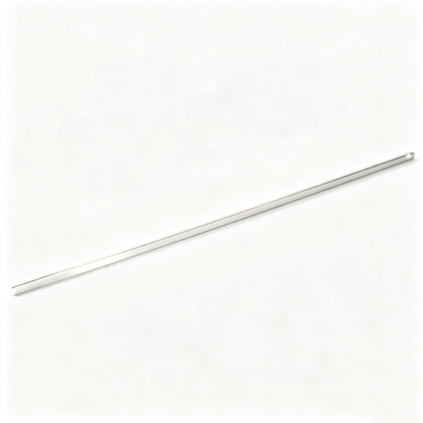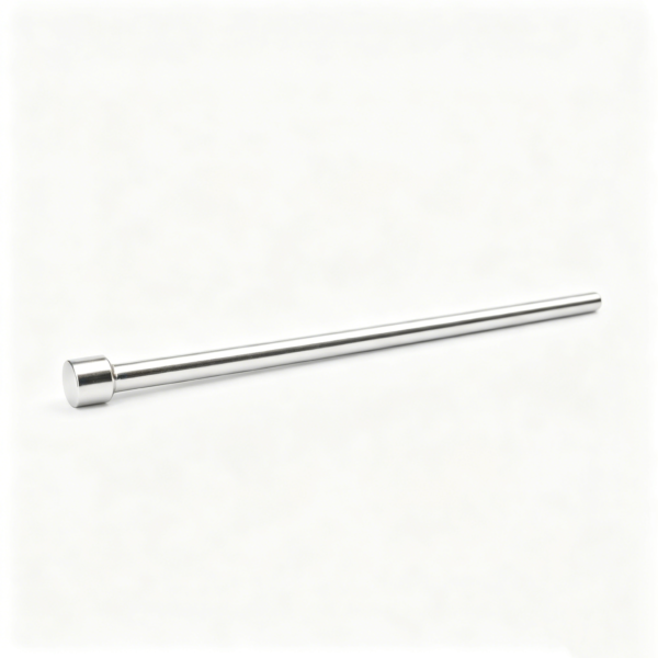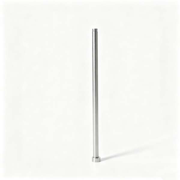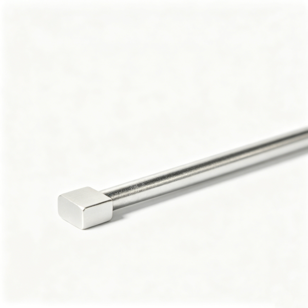
Ejector pin clearance must be defined from the mold design, polymer, operating temperature, venting intent and approved component standards; it cannot be reduced to one universal fit number. Verify both the pin and its running bore with traceable measurements, control straightness and surface condition, and assess the assembly under its actual alignment and thermal context. Excess clearance can contribute to flash or material entry, while insufficient effective clearance can promote binding, wear or pin breakage.
This engineering workflow supports components sourced through XUXIANG’s precision ejector pin program and should be used with released drawings and qualified mold-design review.
Define the Functional Clearance on the Drawing
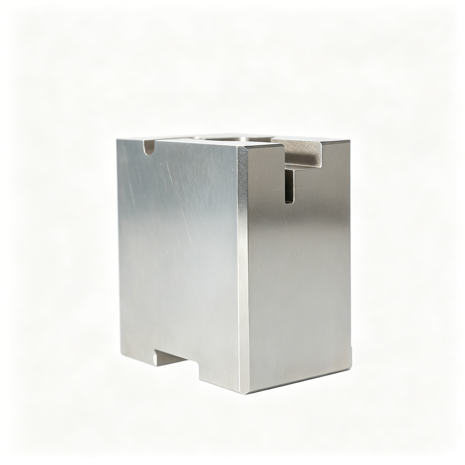
State the pin diameter, bore diameter or fit designation, tolerance, datum system, surface requirements, material, hardness condition and measurement temperature. Identify the functional length over which the fit applies. A single diameter callout without form and alignment controls may not prevent local interference.
The released specification should also identify:
- component standard and revision where applicable;
- ejector pin type and head geometry;
- bore manufacturing method and finish;
- guided and unsupported lengths;
- shutoff or venting role at the cavity end;
- expected process temperature range;
- lubrication policy if allowed;
- inspection method and sampling plan;
- replacement and wear limits.
Do not copy a clearance from an unrelated mold. Resin viscosity, fillers, cavity pressure, pin size, geometry and temperature change the decision.
Measure the Pin at Multiple Sections
Clean and condition the pin according to the inspection procedure. Measure diameter at named axial positions and more than one rotational orientation where the drawing or risk requires it. This reveals taper, lobing or localized damage that one reading can miss.
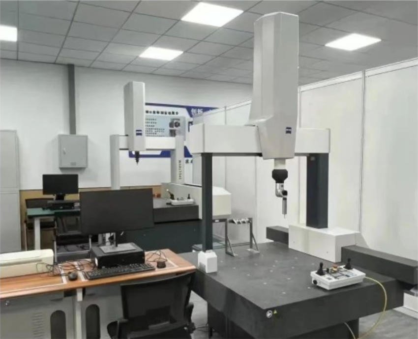
Record the instrument, resolution, calibration status, measurement force or setup, temperature and actual values. If the component has a relieved section, distinguish it clearly from the guided diameter.
Inspect the working end, transition and head for burrs, dents, grinding marks and edge damage. A nominally correct diameter can still bind if a raised burr enters the bore.
Verify Straightness and Runout
Long, slender pins can bend during manufacture, handling, assembly or service. Check straightness or runout using the drawing-defined method and suitable supports. Avoid a setup that sags the part enough to dominate the reading.
Document the support locations and measurement path. If a pin fails, do not straighten it informally and return it to service without an approved repair disposition; residual stress or surface damage may remain.
The Plastics Technology discussion of ejector-pin breakage reinforces a broader point: pin failure is a system problem involving alignment, support and operation, not merely pin hardness.
Inspect the Running Bore
The effective clearance depends on the bore as much as the pin. Verify bore size, roundness, straightness, finish and entry condition according to the drawing. Check for taper, bell-mouth, burrs, embedded debris and machining transitions.
Use gauges and instruments suited to the bore diameter and required uncertainty. A simple go/no-go result may be useful for production screening but may not explain a marginal assembly. For troubleshooting, retain actual profile or sectional readings.
Confirm that the bore is measured after all relevant heat treatment, coating, polishing and assembly operations. Later processes can alter size or introduce distortion.
Calculate Clearance From Actual Mating Results
Pair actual pin and bore readings by location when selective assembly or tight control is required. Report diametral and radial clearance clearly; do not use the word “clearance” without defining which one.
Consider worst-case combinations within the allowed tolerances. A nominal calculation can hide an interference at one limit and excessive clearance at the other. Include form error and alignment where they materially affect the available running space.
The drawing authority should decide whether parts are fully interchangeable or paired. If selective pairing is used, preserve pair identity through assembly and maintenance.
Account for Thermal Expansion
The mold operates at temperatures different from the inspection room. Pin, plate and insert materials may expand differently, and local cavity heat can alter effective clearance. Evaluate the operating condition using verified material properties and the mold’s thermal model or engineering method.
Do not convert a room-temperature fit into an operating guarantee without this review. Record the assumed temperatures, materials and calculation source. Where risk is high, validate through controlled mold trials and monitored ejection behavior.
Thermal context also affects measurement comparison. Condition components to the specified inspection temperature before making micron-level decisions.
Evaluate Surface Finish and Lubrication Policy
Surface roughness, grinding direction, waviness, coating and damage influence friction and wear. Verify the specified surface using the defined instrument, cutoff and direction where required. A generic “polished” note is not a measurable acceptance criterion.
Follow the mold design’s lubrication policy. Some applications restrict lubricants because of contamination, migration or polymer interaction. Do not add grease to solve a binding pin until alignment, bore condition, thermal fit and material compatibility are understood.
Record any approved lubricant, quantity, application point and maintenance interval. A change in product should trigger review rather than silent substitution.
Check Assembly Alignment
Install the pin and ejector system using the approved sequence. Verify plate guidance, pin seating, head clearance, return system and free motion before full machine operation. Look for side loading caused by misaligned plates, poorly located bores or uneven ejector travel.
Move the system through its intended stroke under safe setup conditions. Record binding position and orientation if resistance occurs. Do not hammer a pin through a tight bore; the resulting damage destroys evidence and can score the bore.
Confirm that the pin does not bottom or carry unintended load at the head. Assembly stack and plate movement belong in the same fit review.
Review Cavity-End Function
At the molding surface, the pin end may affect part appearance, flash, venting and ejection load. Inspect end geometry, height relative to the cavity, edge condition and surface match. Define the permissible witness or mark in the part quality standard.
If clearance is intended to support venting, verify that the design remains safe for the specific resin and process. Excessive material entry can lock or damage the pin. Do not enlarge clearance as an informal venting fix.
Track residue and flash during trials. Their location can help distinguish cavity-end leakage from general alignment or wear.
Validate Through a Controlled Mold Trial
Before production release, run the ejector system under approved mold and process conditions. Observe ejection smoothness, return, part release, witness marks, noise and temperature-related change. Inspect pins and bores after the trial interval defined by the validation plan.
Correlate mold behavior with actual dimensional records. If a pin binds only when hot, the root cause may not appear in room-temperature hand fitting. If flash develops progressively, inspect wear and process conditions rather than adjusting the pin alone.
Keep trial parameters and cycle history with the approval record. Without them, later comparisons are weak.
Establish Incoming and Final Inspection
Incoming inspection should confirm identity, material or hardness evidence as specified, key dimensions, straightness, surface and visible condition. Final assembly inspection should verify paired fit, motion, height and traceability.
Use a control plan based on risk, capability and contract requirements. Sample across grinding batches and heat-treatment lots. For critical features, retain actual readings rather than only a pass stamp.
Any nonconformance must receive a documented disposition. Blending, polishing or regrinding changes the component and requires reinspection of affected characteristics.
Manage Wear and Replacement
Create baseline readings and photographs for service. During maintenance, inspect scoring, diameter loss, bending, mushrooming, head wear and cavity-end damage. Inspect the bore at the same time; replacing only the pin may not restore the designed fit.
Use drawing-defined wear limits or engineering disposition. Do not wait for breakage as the replacement trigger. If repeated failures occur at one position, investigate ejection load, cooling, part sticking, alignment and support.
Maintain component and mold-position traceability. A replacement pin must match the released revision and any selective-fit requirement.
Common Verification Mistakes
Using a universal clearance. Mold, resin and operating conditions differ.
Measuring one pin diameter. Taper, lobing and local damage remain hidden.
Ignoring the bore. Effective fit depends on both components.
Checking only at room temperature. Operating expansion can change clearance.
Hand-polishing without records. Size, form and surface may leave specification.
Replacing pins without inspecting alignment. The same failure mechanism persists.
Frequently Asked Questions
What clearance should an ejector pin have?
Use the released mold design based on pin size, resin, temperature, venting, process and component standards. There is no safe universal value.
What causes ejector pins to bind?
Insufficient effective clearance, bore or pin form error, bending, debris, thermal growth, side loading, surface damage and misalignment can contribute.
Is a go/no-go gauge enough?
It can screen a defined size limit, but troubleshooting or tight fits may require actual diameter, form, straightness and bore-profile data.
Should the bore be checked when replacing a pin?
Yes. Wear, scoring or misalignment in the bore can damage the new pin or leave excessive clearance.
Final Verification Principle
Approve ejector pin clearance as an operating assembly characteristic. Drawing-defined fits, traceable pin and bore data, thermal and alignment review, controlled trials and maintenance records provide stronger evidence than a nominal size or hand-feel check.