
Precision Mold Components & CNC Machining — +/-0.001 mm Accuracy, ISO 9001 Certified
XUXIANG delivers precision mold components, custom core inserts and CNC-machined metal parts held to micron-stable tolerances, validated by ZEISS CMM metrology, with quotes returned in 24 hours and full FAI documentation.
Featured Precision Mold Components & CNC Parts
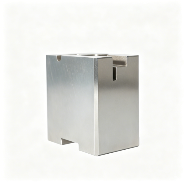
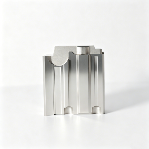
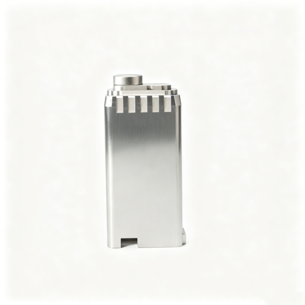
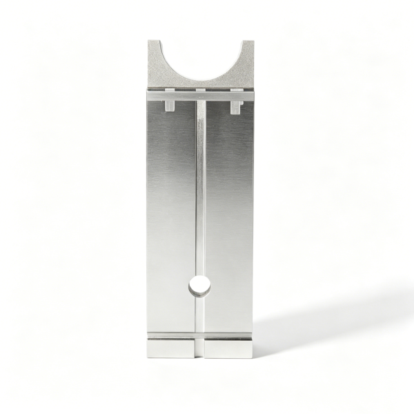
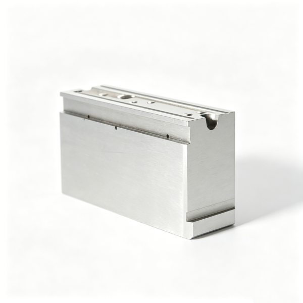
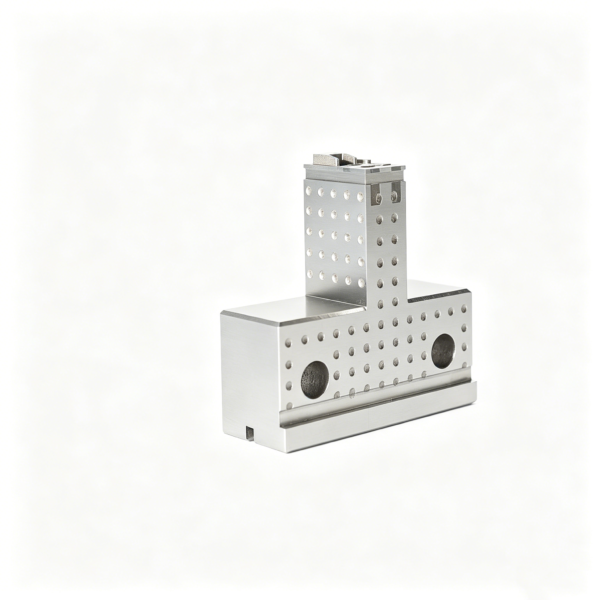
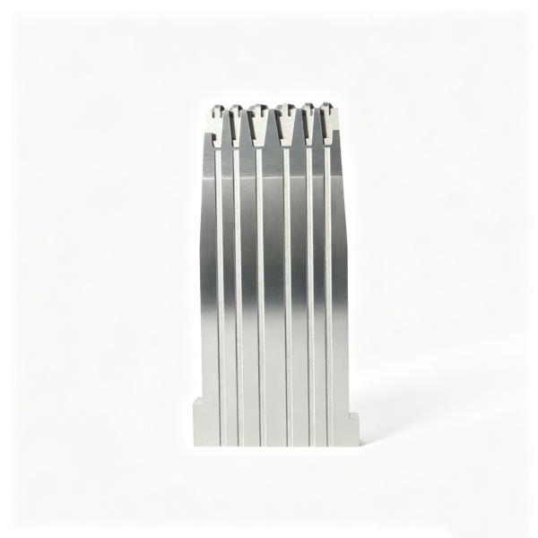
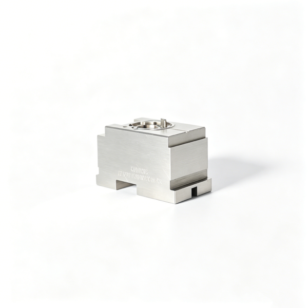
Production Samples & Precision Showcase
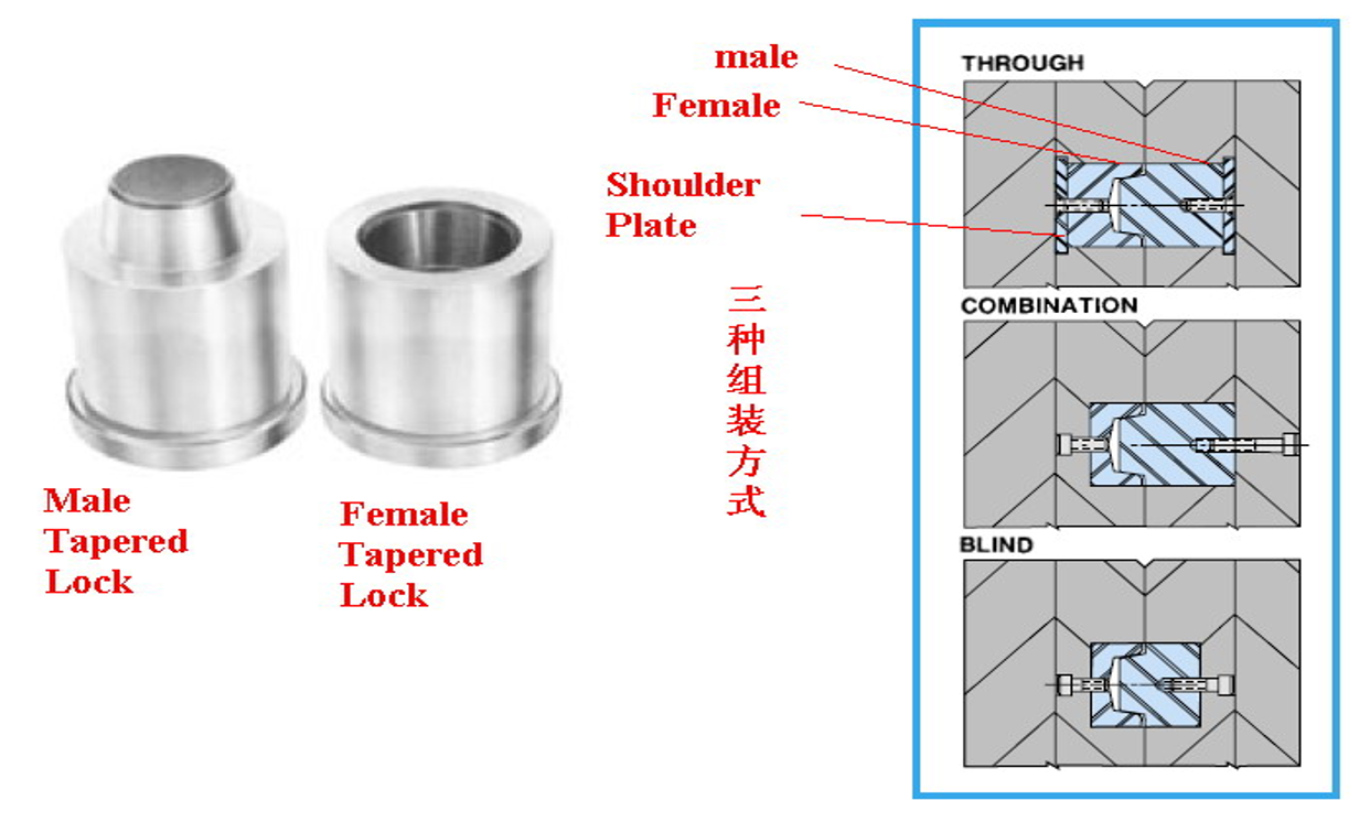
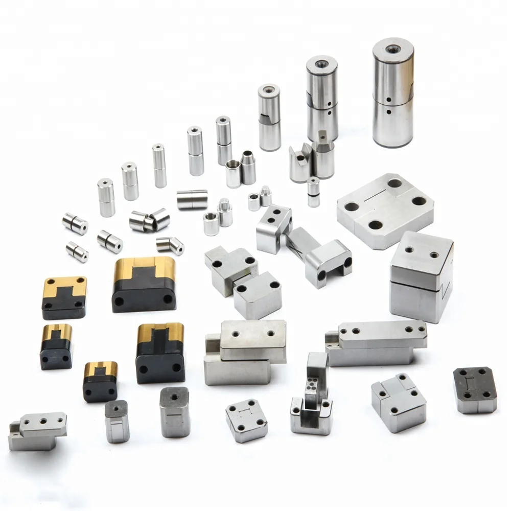
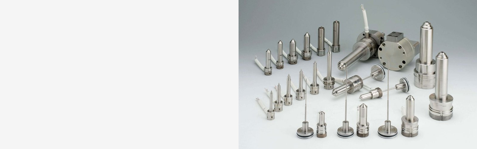

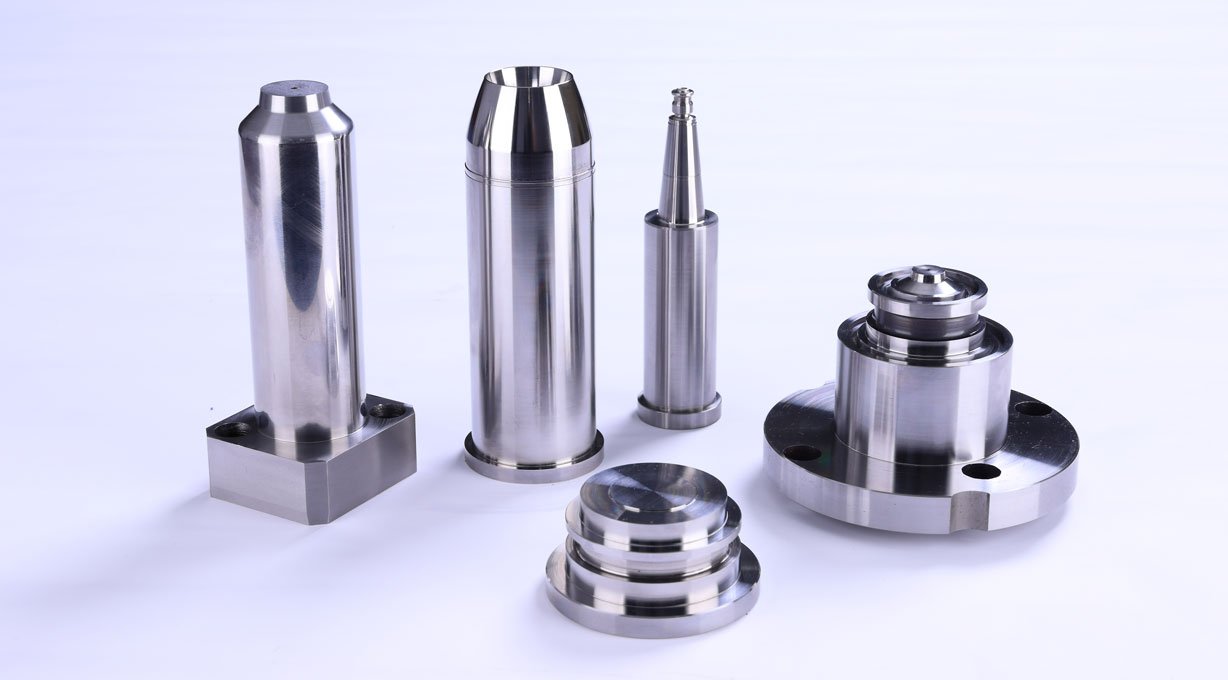
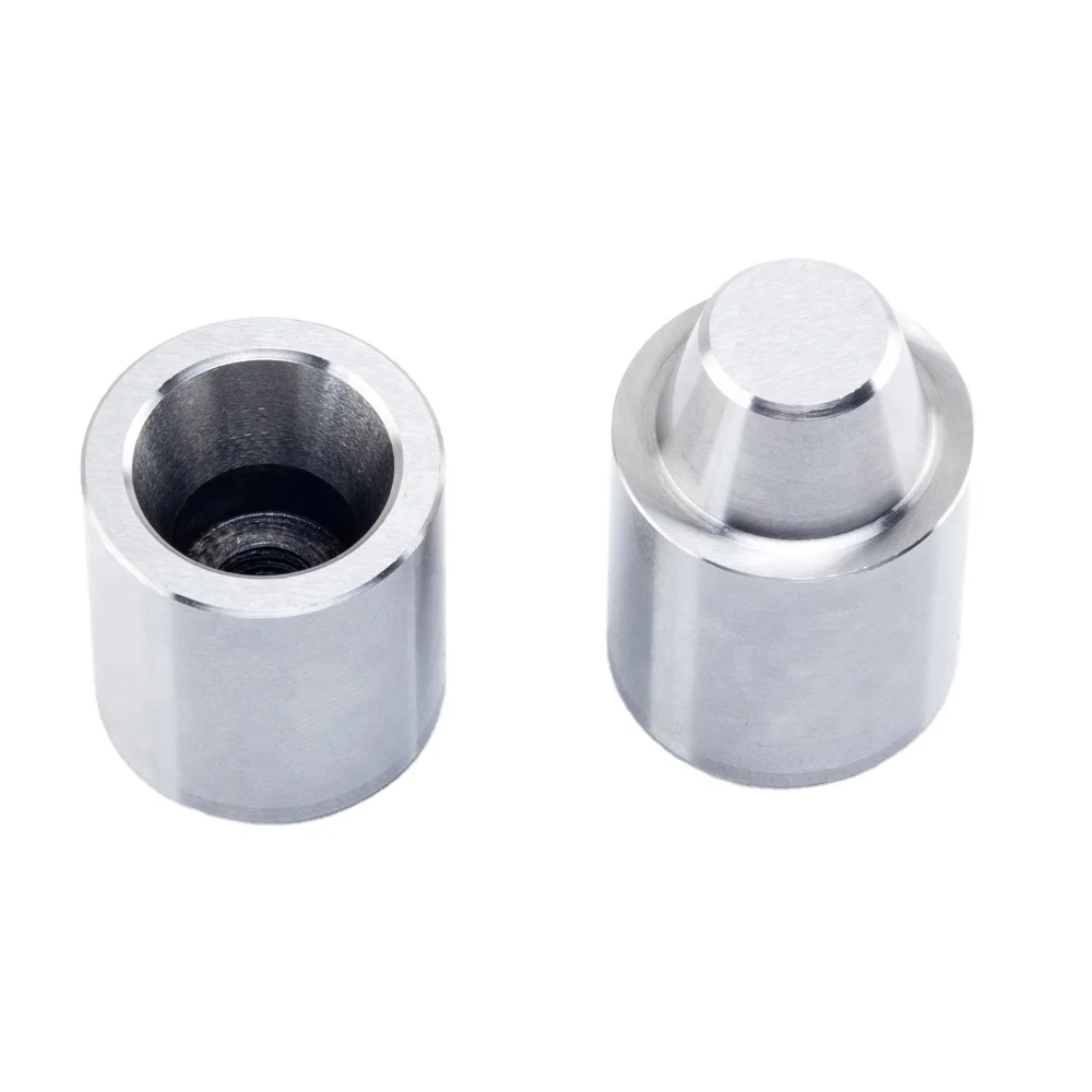
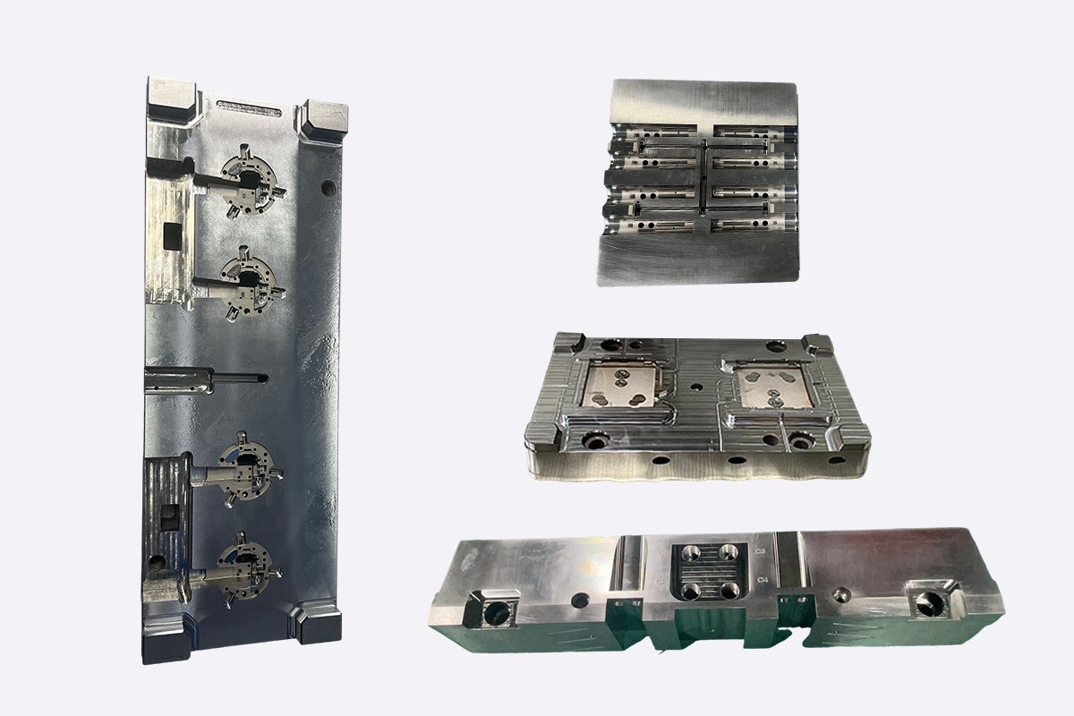
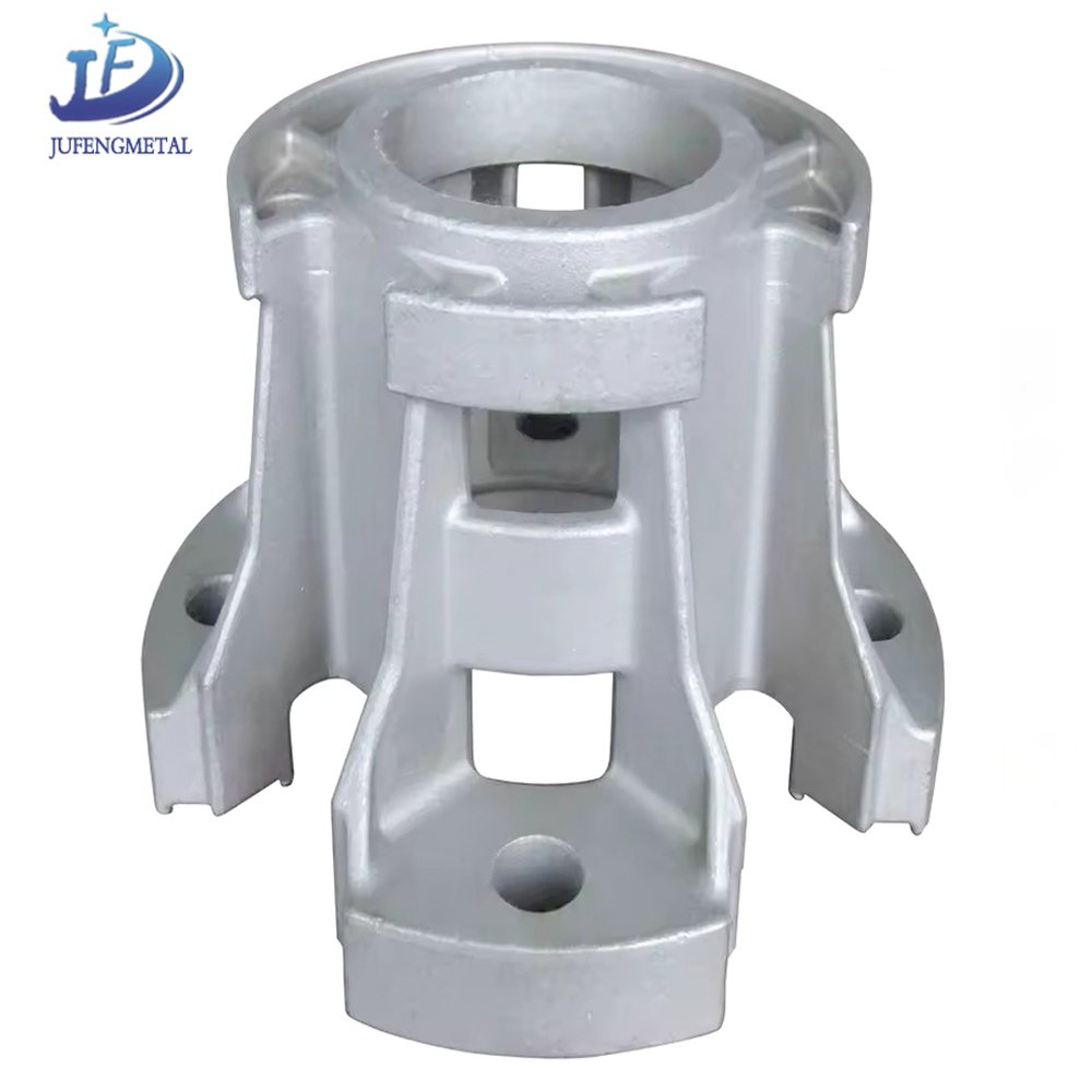
Why XUXIANG’s Precision Mold Components Stand Out
+/-0.001 mm Machining Precision
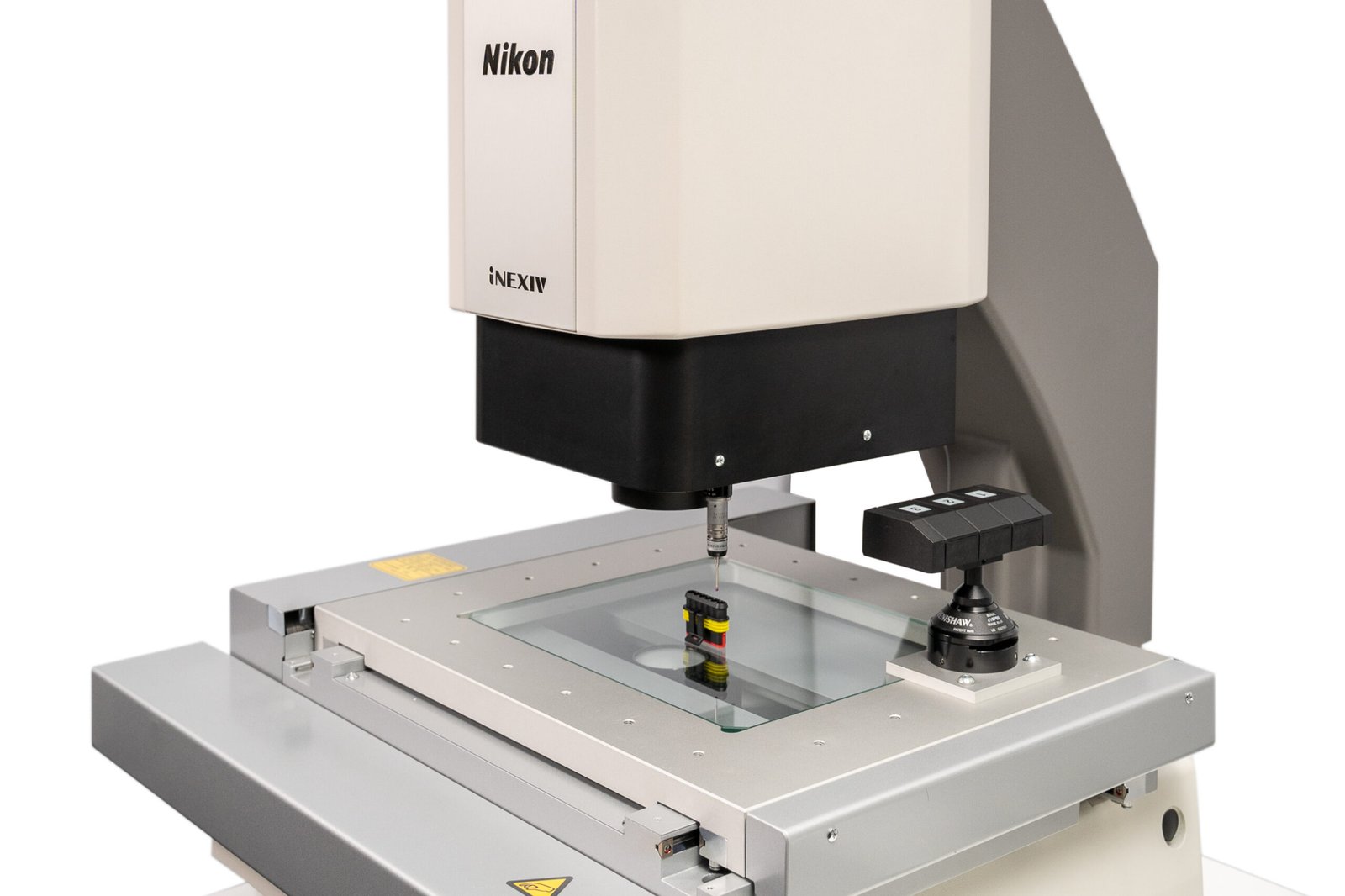
Micron-stable accuracy verified by ZEISS MICURA CMM and Nikon toolmaker’s microscopes, eliminating tolerance failure and costly rework cycles.
Ra 0.1um Mirror-Grade Finish
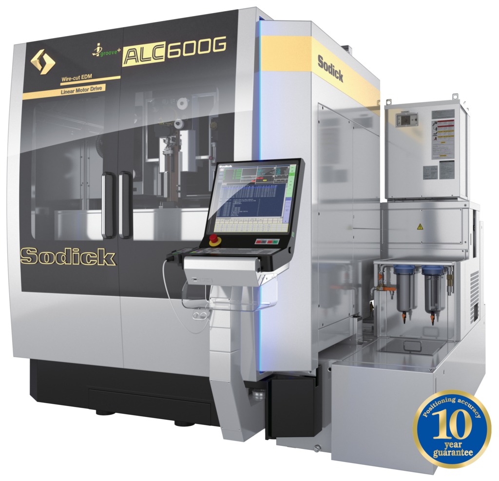
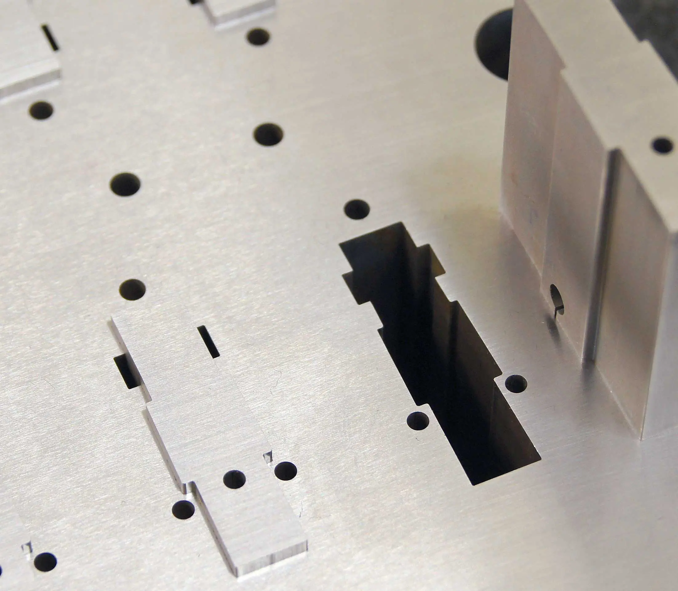
Sodick slow-wire EDM and Mitsubishi mirror EDM deliver optical-class surface integrity for critical mating surfaces and connector tooling.
Full FAI & Material Certificates
Every shipment includes first-article inspection reports, spectral analysis and dimensional validation—complete traceability for ISO 9001:2015 compliance.
24-Hour Quote Turnaround
Upload your CAD files and receive engineered DFM feedback plus transparent pricing within one business day, accelerating procurement cycles.
Dual-Factory Production Capacity
Dongguan R&D hub plus Quanzhou volume line deliver 200% expanded output, balancing prototype agility with dependable mass production.
3–7 Day Sample Delivery
Samples ship in as little as three days, with mass production completed in 15–25 days—roughly 30% faster than industry average.
Precision Mold Components & Tooling by Application
Complex mold cores, precision inserts and CNC-machined tooling held to +/-0.001 mm precision — from 5G micro-connectors to automotive sensors — backed by ZEISS CMM validation and ISO 9001:2015 quality control.
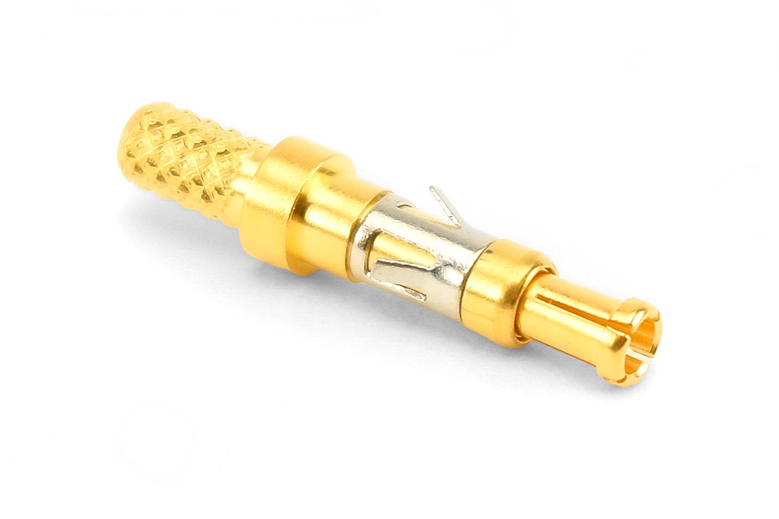
MIM Connector Pins
High-density connector pins for 5G, mobile and board-to-board applications. MIM delivers thin-wall geometries, tight concentricity and batch-to-batch repeatability that conventional machining cannot match economically. Validated on ZEISS MICURA CMM to 0.7um resolution; supplied with full dimensional reports and material certificates.
Get a Quote
MIM Micro Gears
Precision micro gears for miniature actuators, medical instruments and robotic assemblies. MIM enables complex tooth profiles, fine pitch and material consistency in stainless steel, tool steel or specialty alloys. Held to +/-0.002 mm class positioning; inspected under Nikon toolmaker’s microscope for tooth-form accuracy and surface integrity.
Get a Quote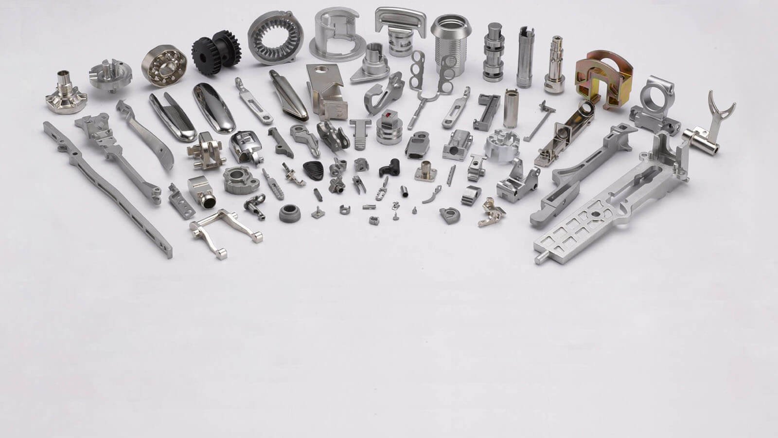
MIM Medical Components
Biocompatible housings, surgical-instrument components and implantable-device hardware in 316L stainless steel or titanium alloys. MIM combines design freedom with the cleanliness and traceability medical OEMs demand. Every lot ships with material certificates, FAI documentation and compliance to ISO 9001:2015 quality protocols.
Get a Quote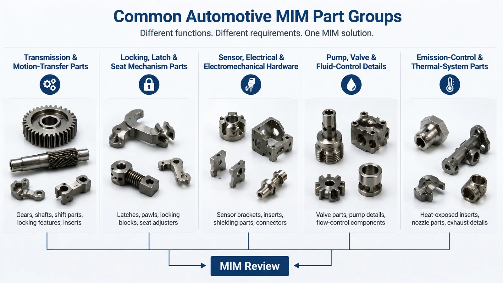
MIM Automotive Parts
ADAS sensor brackets, powertrain fasteners, BMS interconnect hardware and interior functional clips for automotive and new-energy-vehicle platforms. MIM supports lightweighting, corrosion resistance and high-volume repeatability. DFM feedback from 10+ engineers ensures manufacturability; lead times 15–25 days for production volumes.
Get a Quote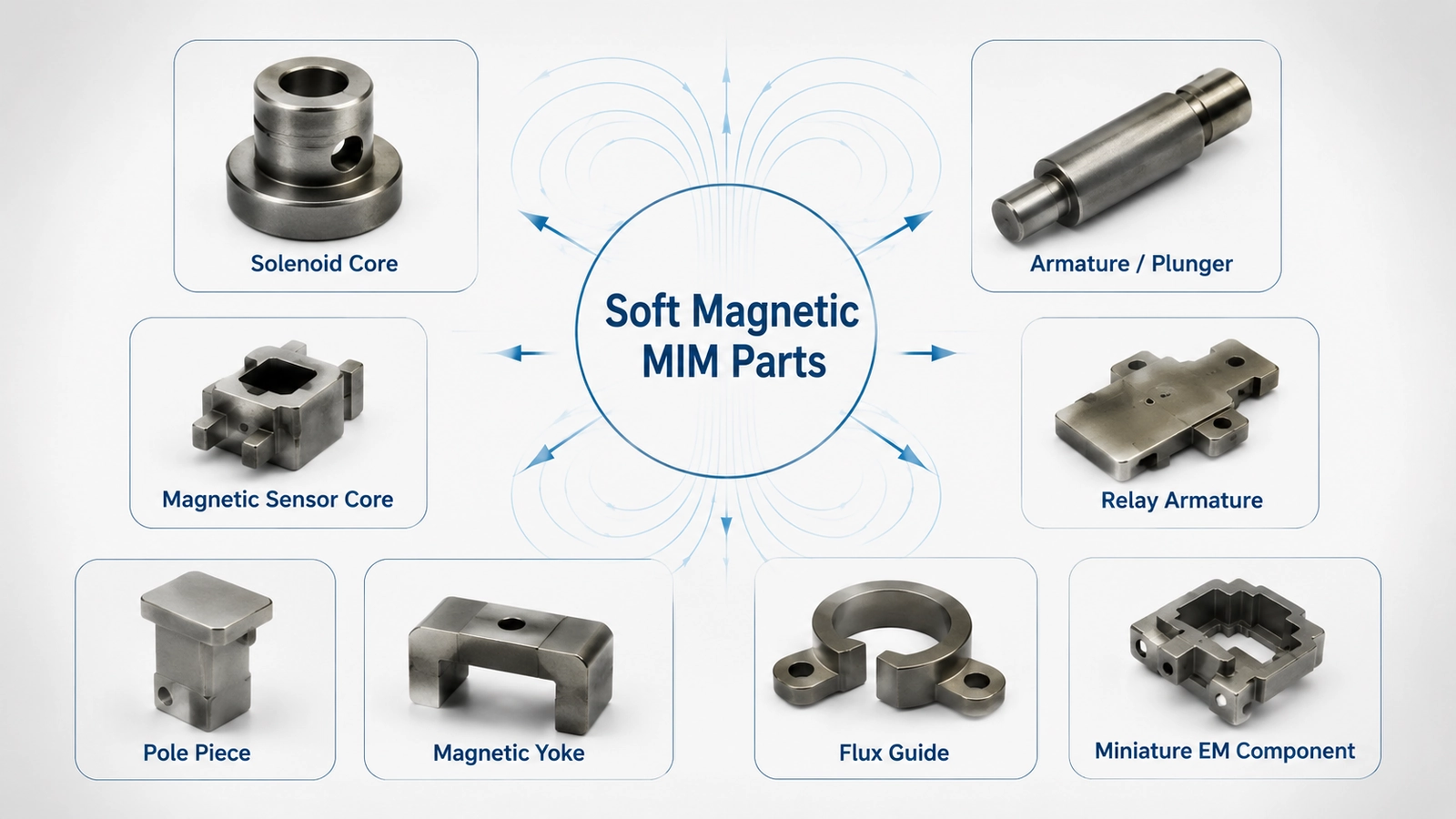
MIM Sensor Housings
Compact, hermetic housings for pressure sensors, temperature probes, ADAS radar modules and industrial IoT devices. MIM achieves wall thicknesses below 0.5 mm, tight flatness and integrated mounting features in a single sintered part. Metrology validated on ZEISS CMM; Ra 0.1um mirror finish available via post-EDM polishing.
Get a Quote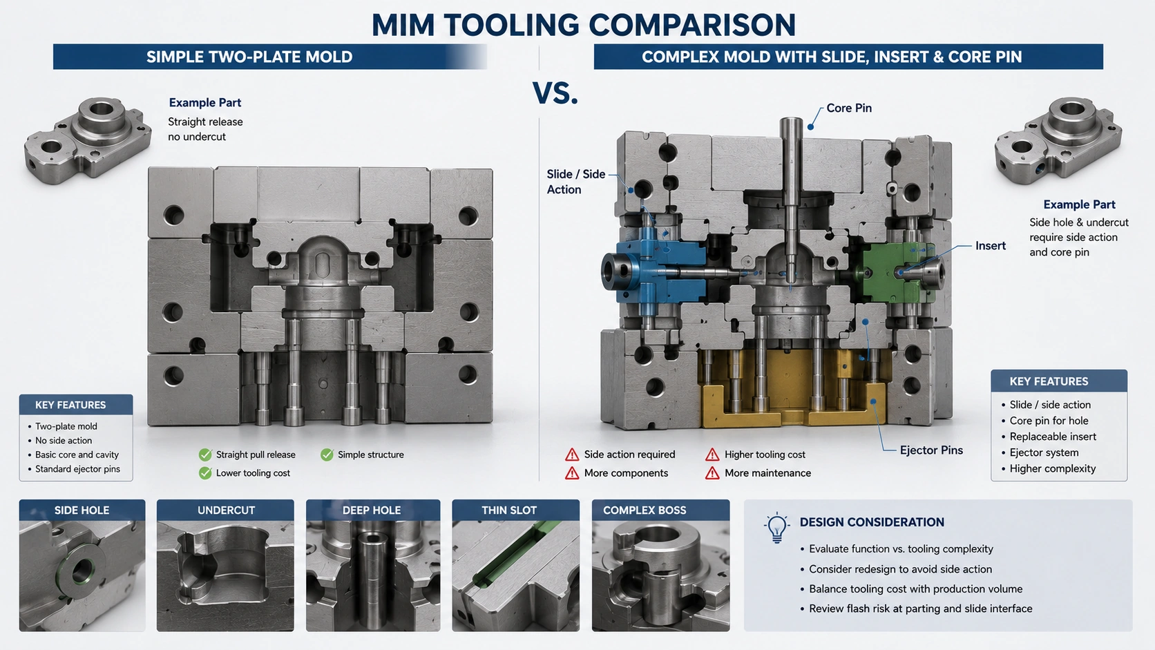
MIM Tooling Inserts
Core pins, ejector pins, lifter inserts and wear components for high-cavitation plastic-injection molds. MIM tool-steel inserts offer superior hardness uniformity and dimensional stability versus conventional machining. Heat-treated to HRC 58–62; ground to final tolerance +/-0.001 mm; compatible with conformal cooling and mirror-EDM finishing.
Get a Quote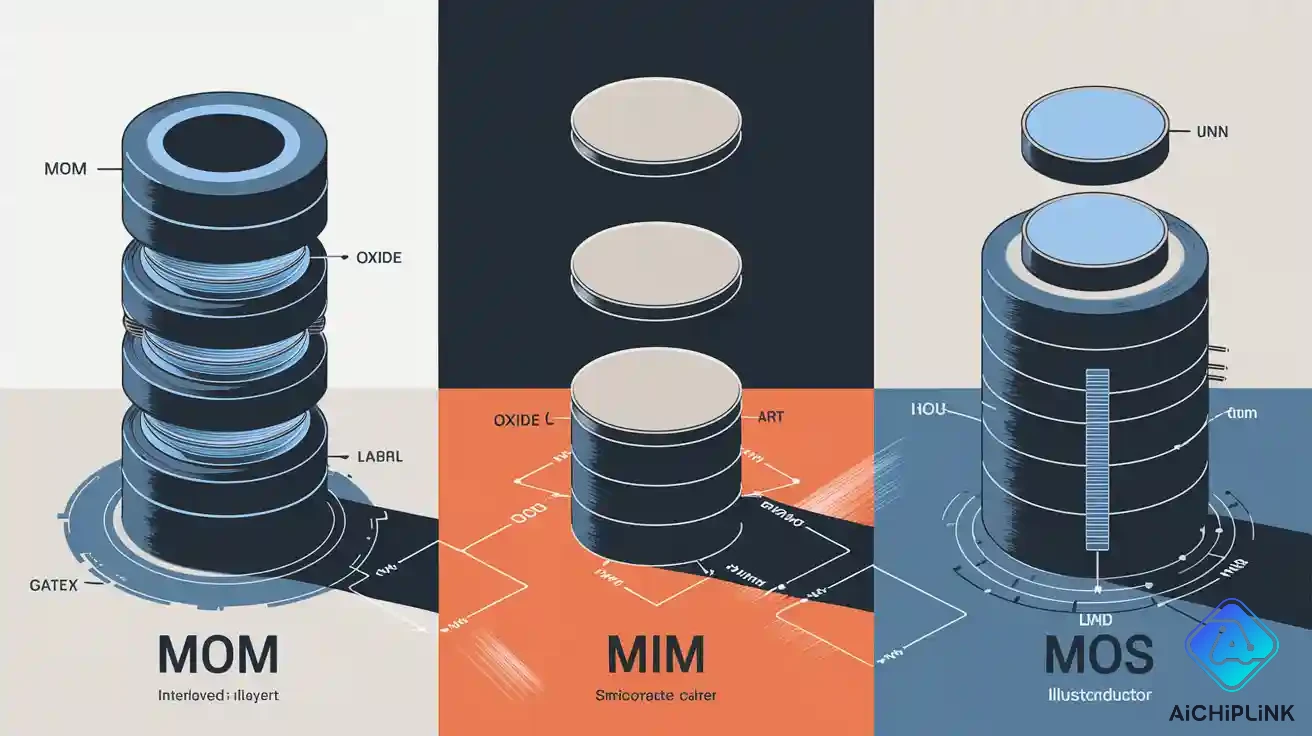
MIM Telecom Components
RF shields, antenna brackets, fiber-optic alignment sleeves and high-frequency connector bodies for 5G base stations and telecom infrastructure. MIM enables tight electromagnetic shielding tolerances and complex internal channels. Supplied with full traceability; quote returned in 24 hours; sample delivery in 3–7 days.
Get a Quote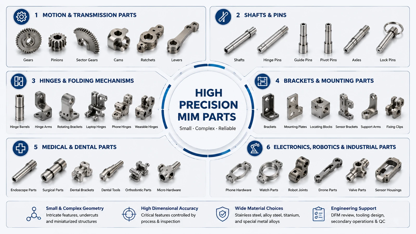
MIM Precision Brackets
Structural supports for LED modules, mounting brackets for industrial cameras and precision positioning hardware for automation equipment. MIM combines the strength of wrought metal with near-net-shape economics. Sodick slow-wire EDM and Fanuc CNC available for post-sinter secondary operations; ISO 9001:2015 process control throughout.
Get a Quote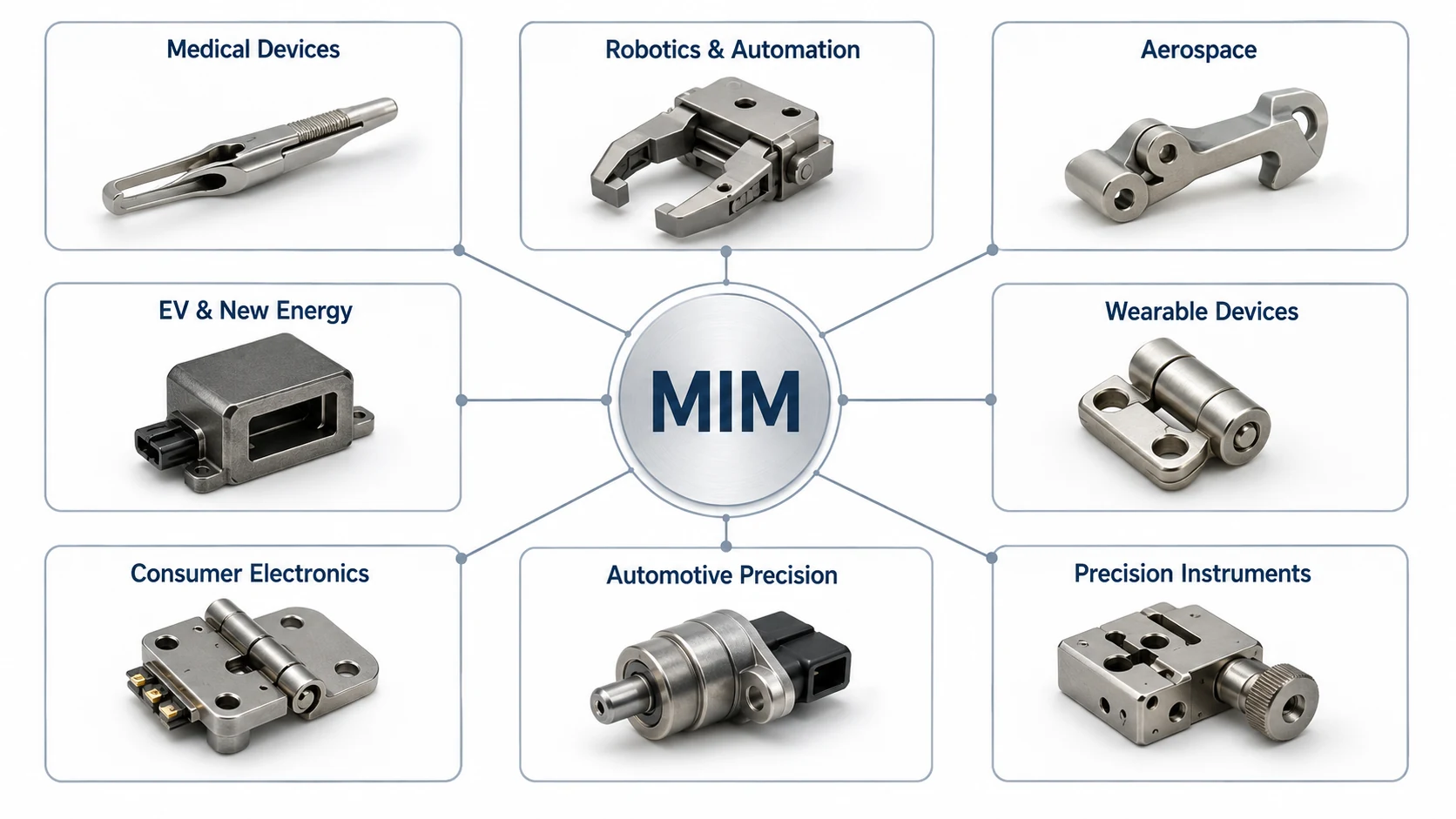
MIM Fasteners & Hardware
Threaded inserts, captive screws, standoffs and custom fastening hardware in stainless steel, carbon steel or exotic alloys. MIM delivers thread accuracy, corrosion resistance and cost efficiency at volumes from 10,000 to 1,000,000+ pieces. Five-step QC flow includes spectral analysis, in-process monitoring and final CMM verification before shipment.
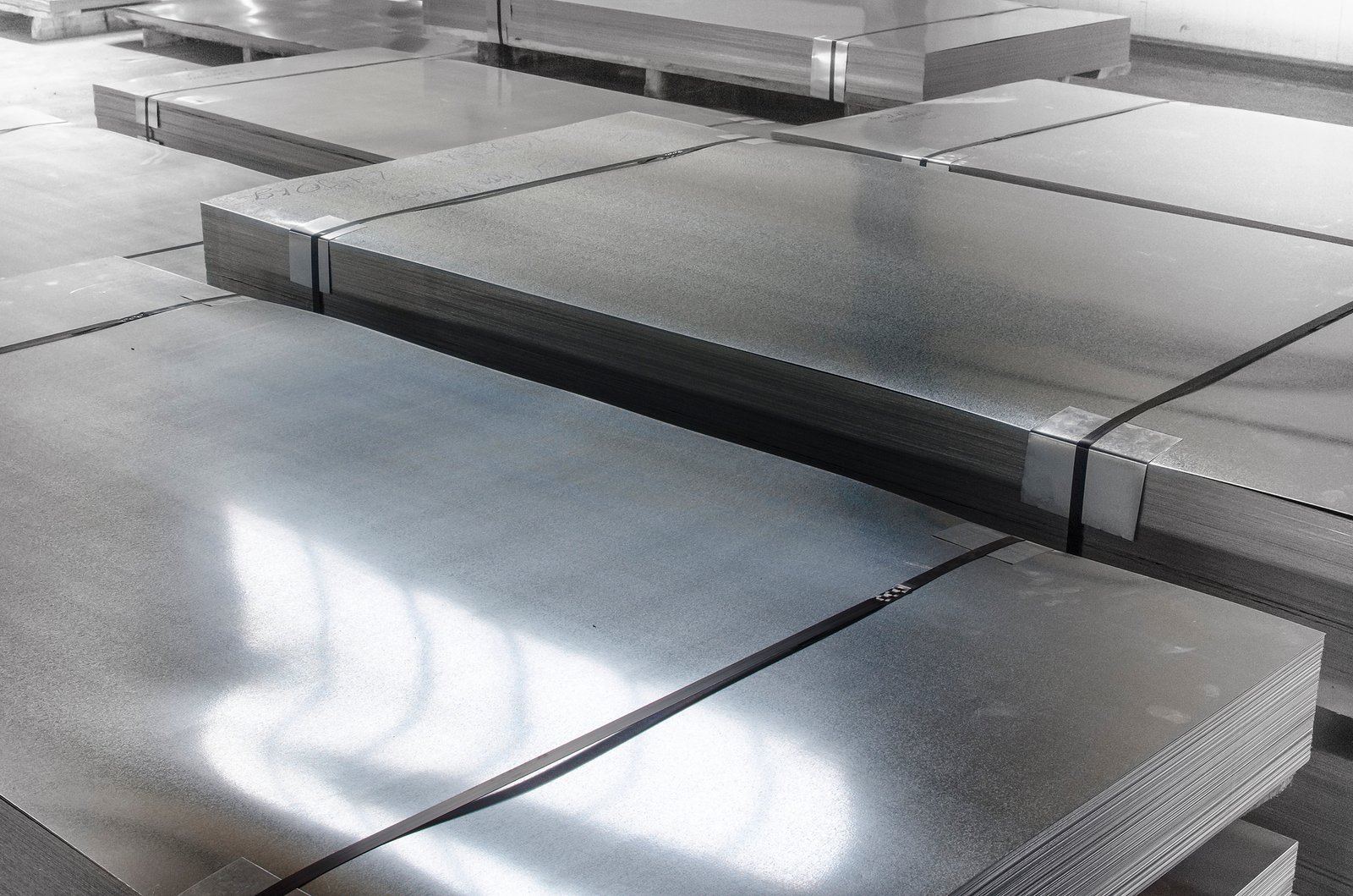
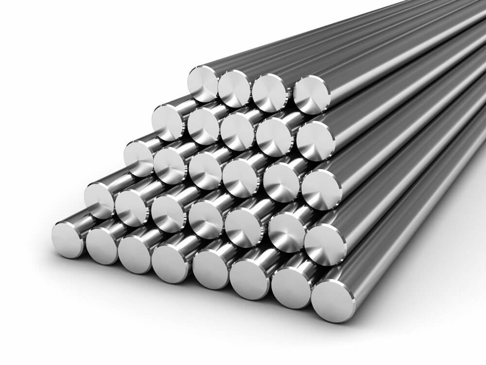
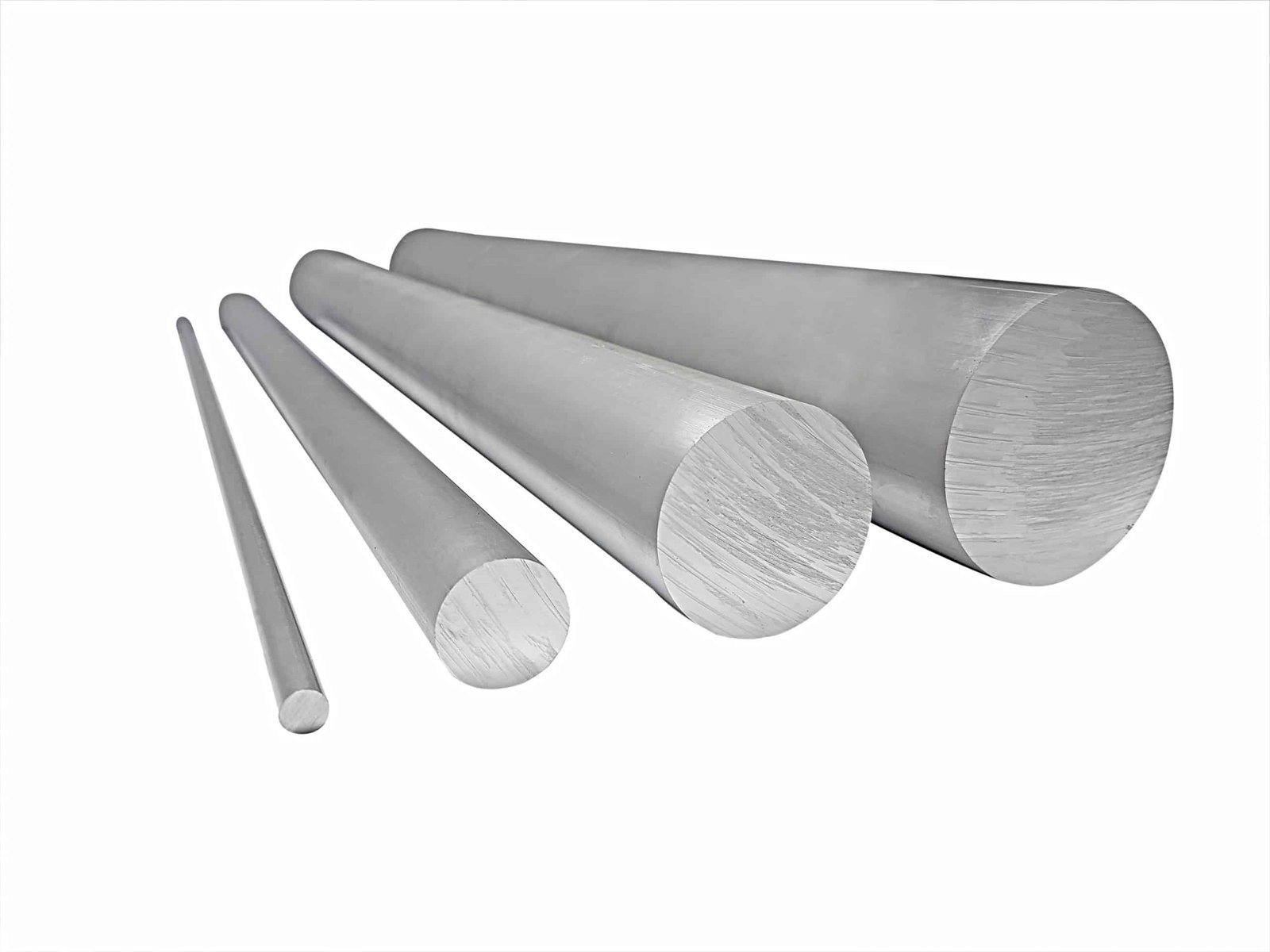
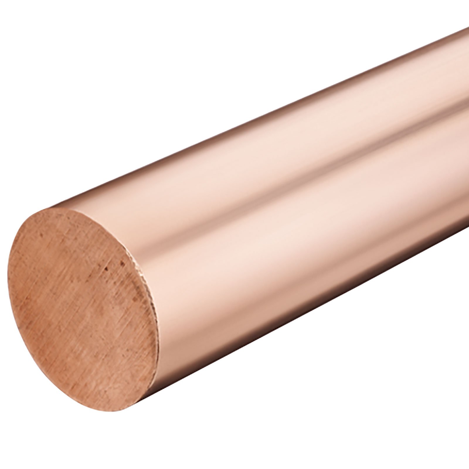
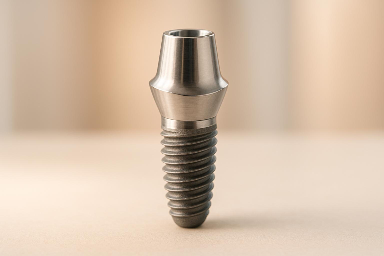
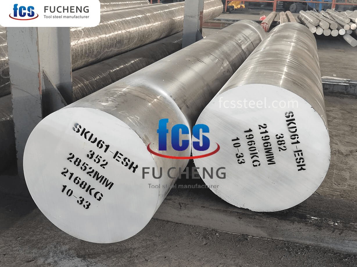
Get a QuotePrecision Alloys & Mold Steels for CNC Machining and EDM
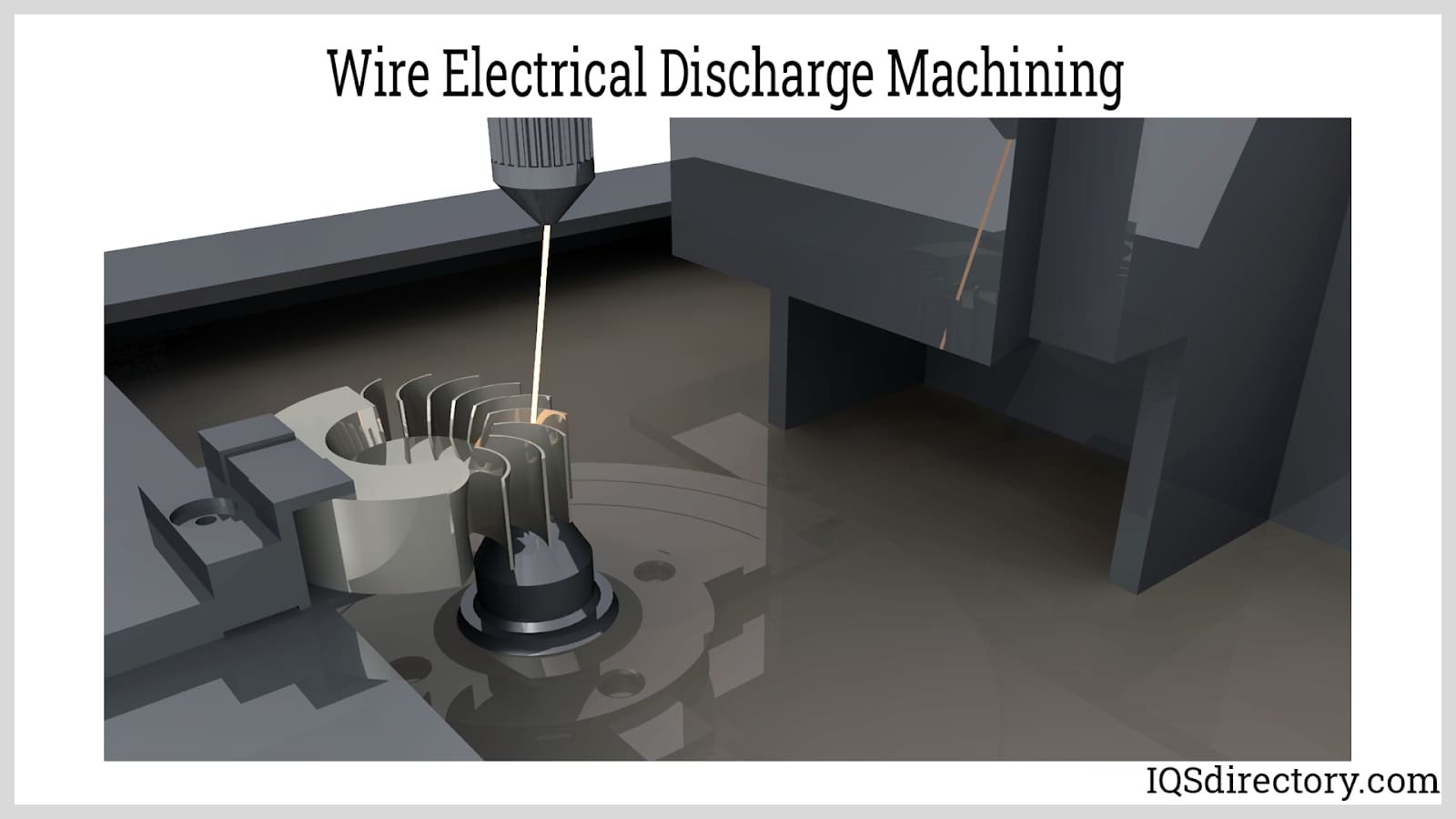
Precision Machining & EDM Processes for Mold Components
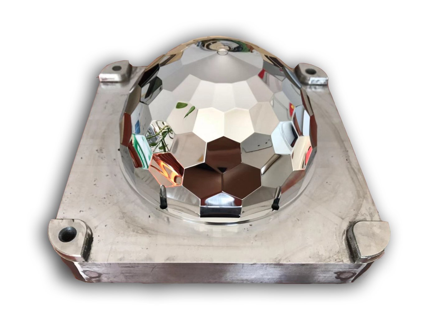
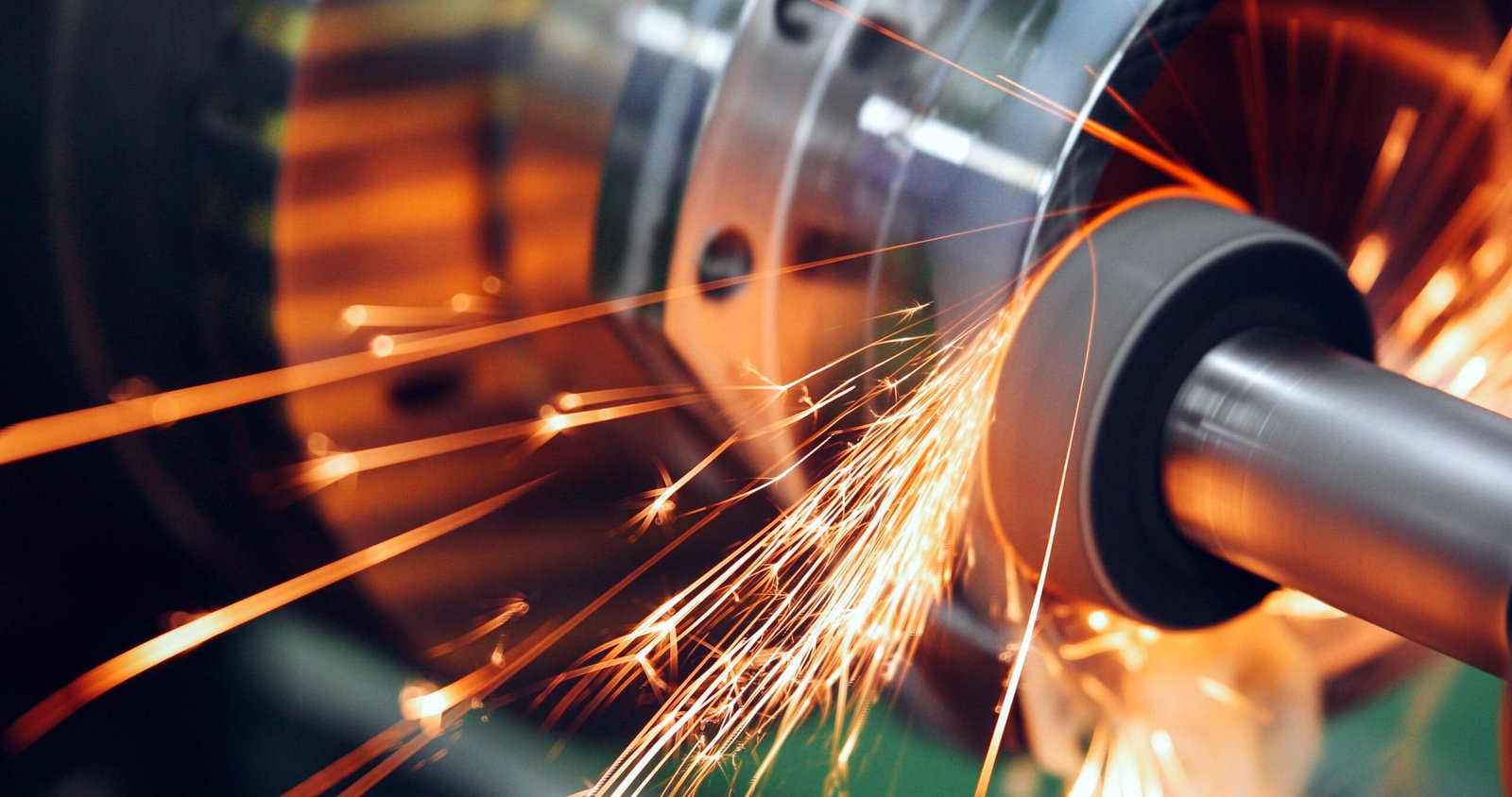
Mirror EDM
Mitsubishi mirror-grade electrical discharge machining achieves Ra 0.1 µm surface finishes on metal injection molded components, eliminating secondary polishing for optical-quality surfaces, micro-connector cavities and high-cosmetic automotive tooling.
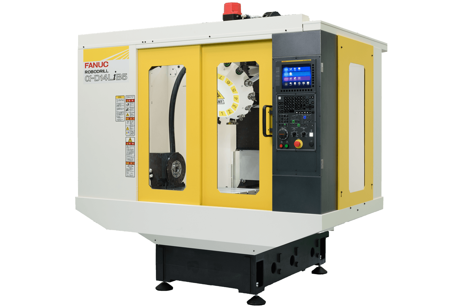

ZEISS CMM Validation
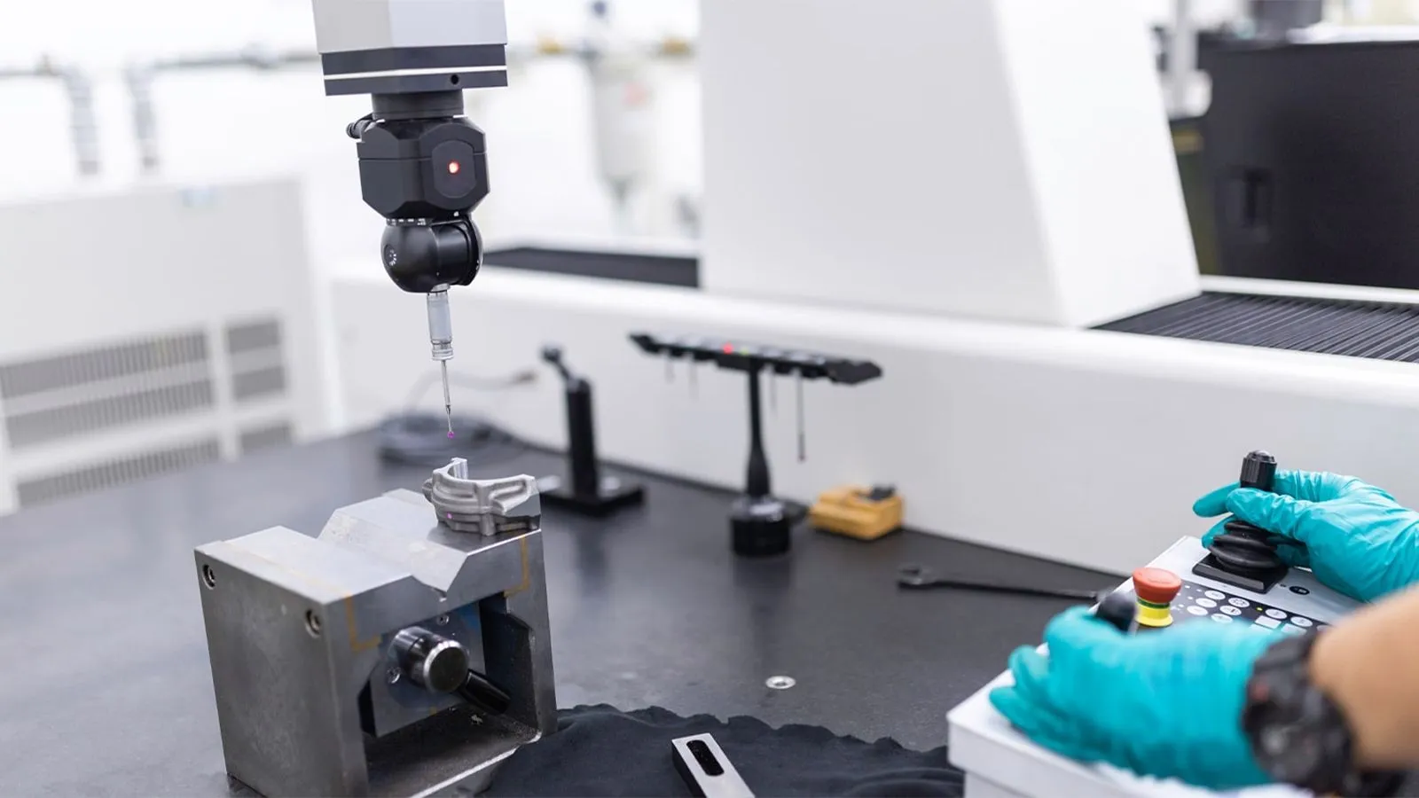
Every metal injection molded component is verified on our ZEISS MICURA coordinate measuring machine with 0.7 µm resolution, backed by Nikon toolmaker’s microscopes, ensuring full-dimensional traceability and FAI documentation with material certificates.
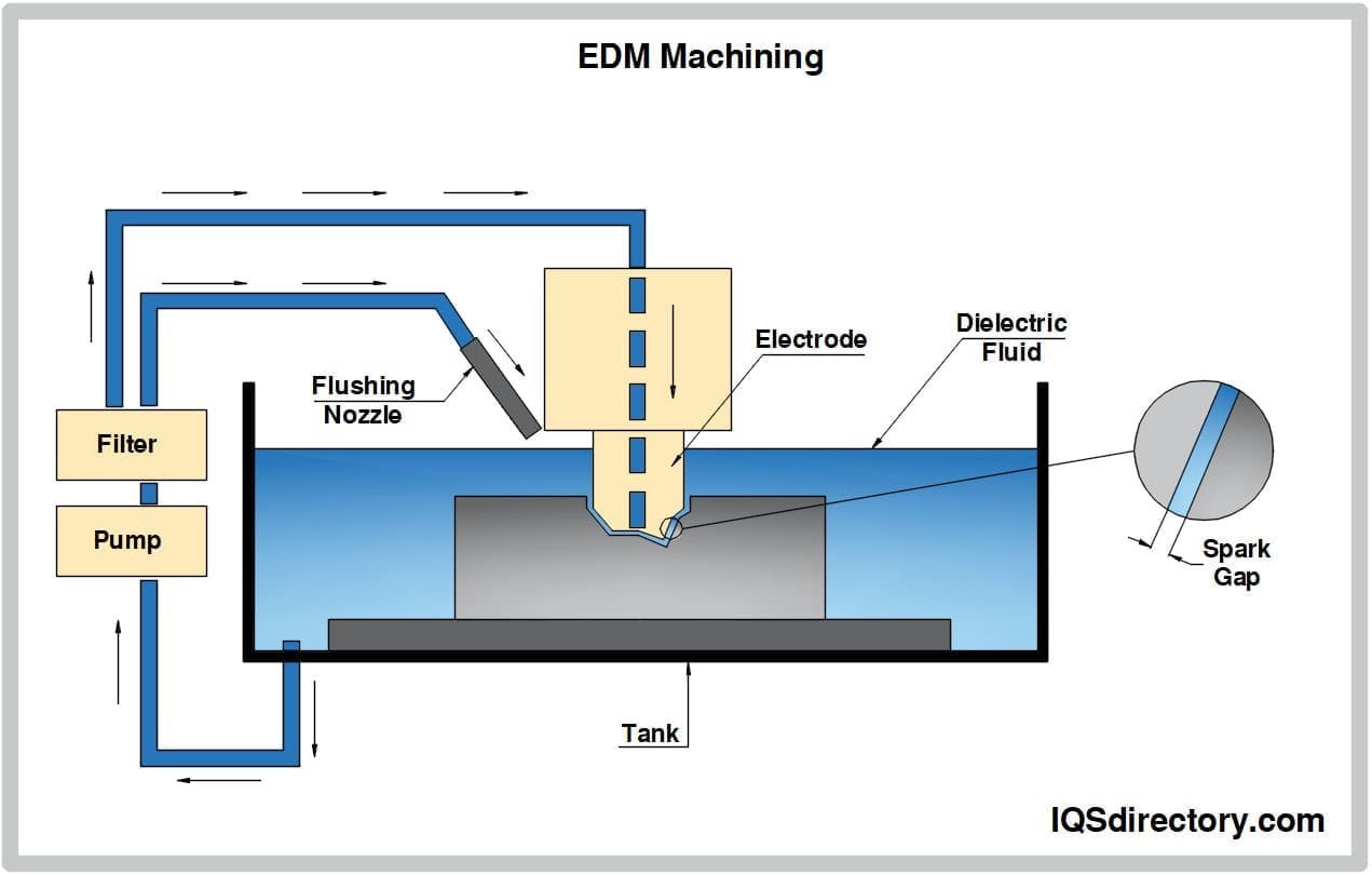
Sinker EDM
Sodick and Charmilles sinker EDM machines produce deep ribs, blind cavities and complex three-dimensional profiles in metal injection molded components with +/-0.003 mm accuracy, ideal for automotive sensors and connector tooling.
Finishing & Assembly Services for Precision Mold Components
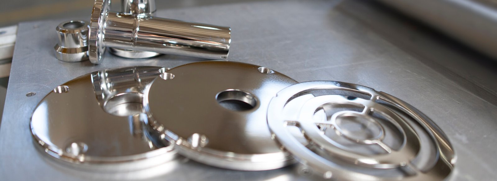
Electropolishing
Removes surface imperfections and micro-burrs from metal injection molded components, delivering a smooth, corrosion-resistant finish ideal for medical-device housings, automotive sensors and clean-room applications where biocompatibility and cleanability are critical.
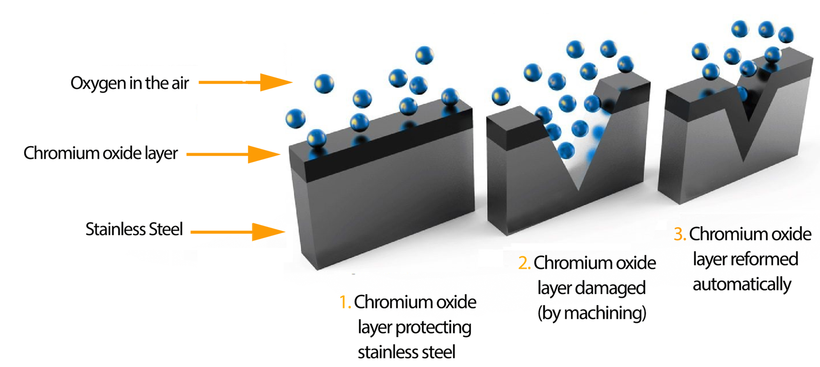
Passivation Treatment
Chemical passivation creates a protective oxide layer on stainless-steel metal injection molded components, enhancing corrosion resistance and extending service life in harsh environments — automotive underhood, marine electronics and industrial automation.

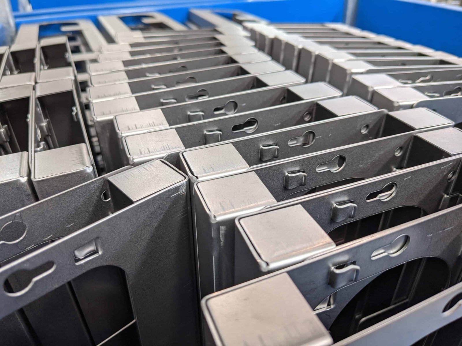
Assembly & Sub-Assembly
Full turnkey assembly of metal injection molded components with springs, pins, O-rings or inserts — validated by ZEISS MICURA CMM and delivered with FAI documentation, reducing your supply-chain complexity and accelerating time-to-market.

Laser Marking & Engraving
Permanent, high-contrast part numbers, date codes, QR codes or logos etched onto metal injection molded components for traceability and compliance — critical for automotive PPAP, medical-device UDI and electronics lot control.
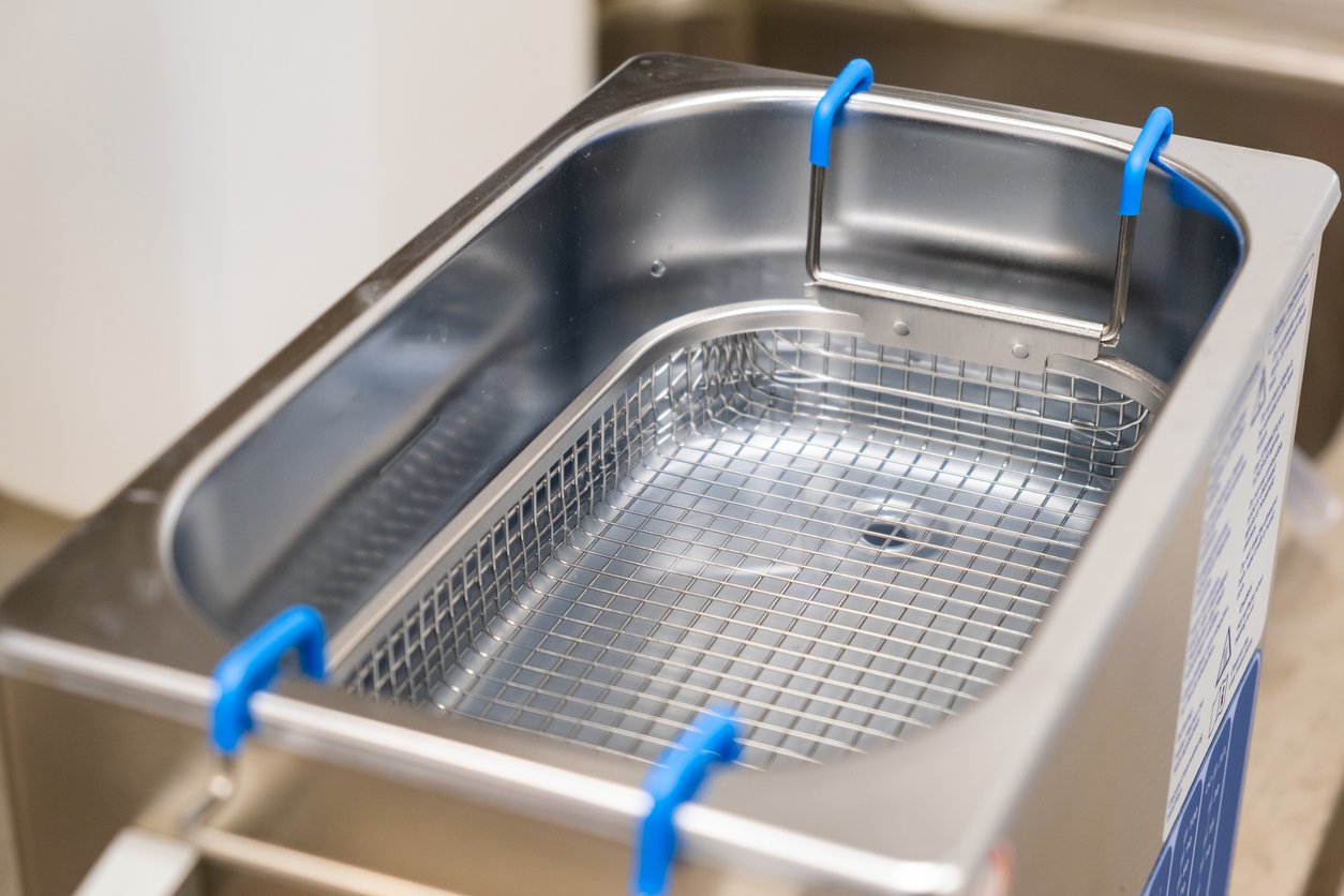
Ultrasonic Cleaning
Multi-stage ultrasonic degreasing and decontamination removes machining oils, particulates and residues from metal injection molded components, ensuring Class 100 cleanliness for medical, semiconductor and precision-connector applications before packaging.
About XUXIANG — 16 Years of Precision Manufacturing
Founded in 2010 in Dongguan’s Chang’an manufacturing hub, XUXIANG has evolved from a specialist mold-core machining shop into a dual-factory precision manufacturing group serving electronics, 5G/telecom, automotive & NEV, industrial automation and medical-device customers worldwide. Our mission is to bridge the gap between complex CAD designs and high-performance metal injection molded components that meet micron-stable tolerances.
Today XUXIANG operates 2,000 m² of R&D and micro-machining space in Dongguan plus a 1,400 m² volume-production facility in Quanzhou, backed by over CNY 8 million in Japanese, Swiss and German equipment — including Sodick slow-wire EDM, Mitsubishi mirror EDM, Fanuc CNC and ZEISS MICURA CMM metrology. This infrastructure enables us to hold +/-0.001 mm machining precision and Ra 0.1um mirror-grade finishes on every part.
What sets XUXIANG apart is our engineering-first approach: every project receives DFM feedback from 10+ experts before production, undergoes five-step QC validation with full FAI documentation, and ships with material certificates. ISO 9001:2015 governs every process, and our 2025 expansion has increased annual capacity by 200% while maintaining lead times 30% faster than industry average — delivering precision without compromise.

Metal Injection Molded Components Engineered and Validated
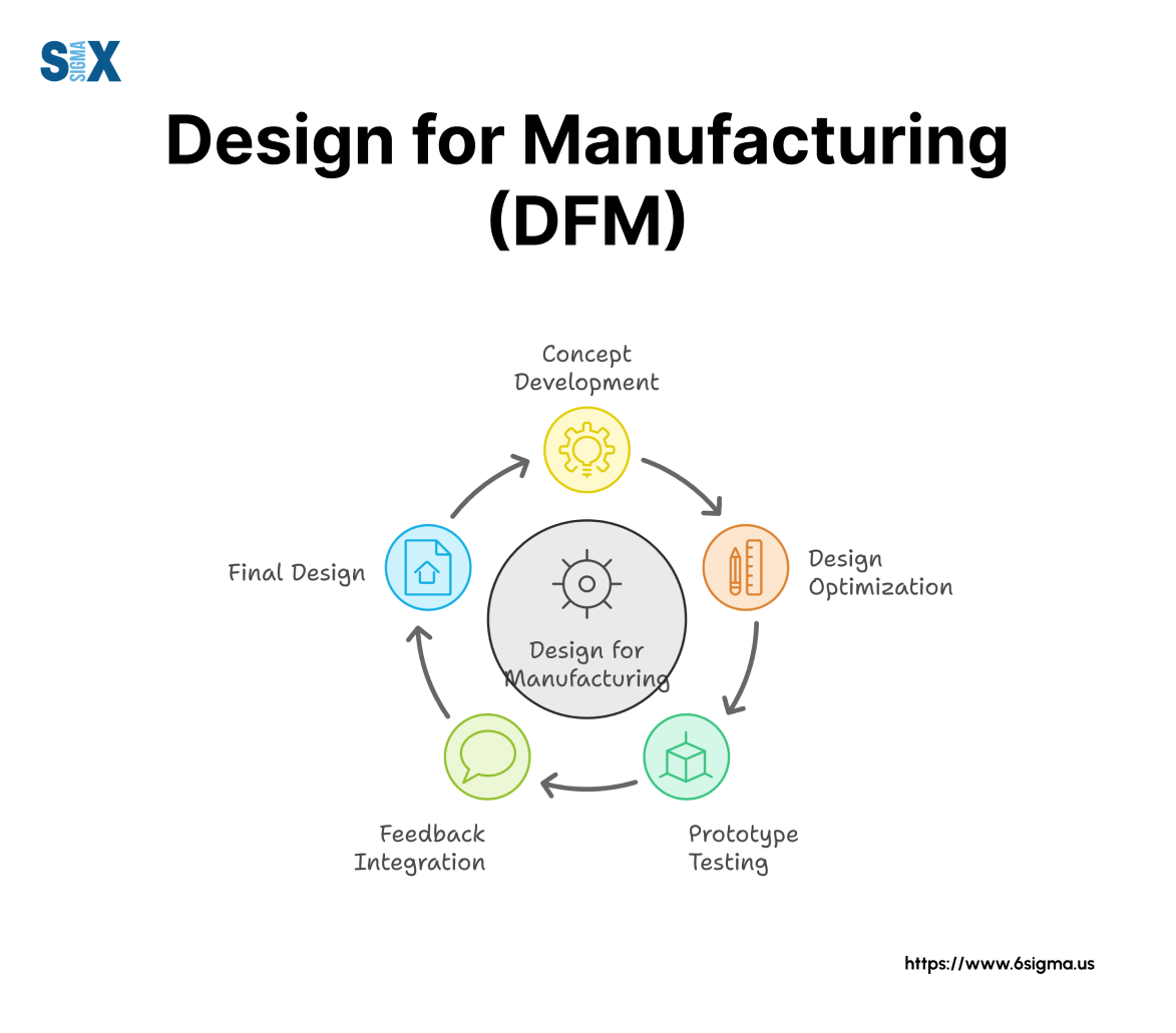
DFM Engineering Before Production Begins
Every metal injection molded component receives upfront design-for-manufacturability analysis from XUXIANG’s team of 10+ precision-mold engineers. You get actionable feedback on wall thickness, gate location, ejection geometry and tolerance feasibility — eliminating costly revisions and ensuring first-run success.
- DFM review within 24 hours of CAD submission
- Tolerance-stack analysis and gate-location optimization
- Material-selection guidance for thermal and mechanical requirements
- Collaborative engineering support through WeChat, email and video call
In-Process Tolerance Monitoring and Control
XUXIANG monitors dimensional stability at every stage — from electrode fabrication through slow-wire EDM and final grinding. Real-time CMM checks and on-machine probing ensure metal injection molded components hold +/-0.001 mm before they reach final inspection, reducing scrap and accelerating delivery.
- On-machine probing during CNC and EDM operations
- Intermediate CMM verification after each critical machining step
- SPC charting for repeat orders to track process drift
- Immediate corrective action when tolerance trends approach limits
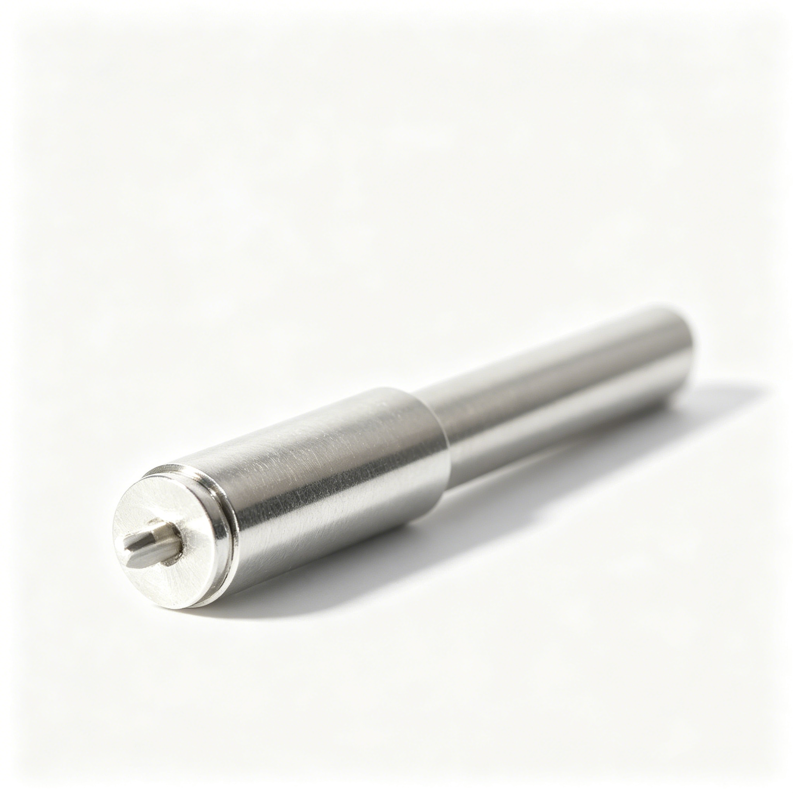
ZEISS CMM Validation and FAI Documentation
Final validation is performed on a ZEISS MICURA coordinate measuring machine with 0.7 µm resolution, backed by Nikon toolmaker’s microscopes for edge quality and surface integrity. Every shipment of metal injection molded components includes a full First Article Inspection report and material certificates.
- ZEISS MICURA CMM inspection to 0.7 µm resolution
- Nikon V-12B / MM-400 class microscope verification of critical features
- Full FAI report with dimensional data, surface finish and geometric tolerances
- Material certificates including spectral analysis and hardness testing
ISO 9001:2015 Quality System
XUXIANG’s dual-factory operation in Dongguan and Quanzhou is governed by ISO 9001:2015 procedures, ensuring traceability, repeatability and accountability across every order. From incoming-material inspection to final packaging, metal injection molded components are tracked, documented and archived for full auditability.
- ISO 9001:2015 certified quality-management system
- Incoming material spectral analysis and hardness verification
- Batch traceability and digital work-order tracking
- Archival of inspection data and process parameters for repeat orders

Precision Mold Components Engineered and Validated
When precision, delivery speed and documentation matter, here’s how XUXIANG’s metal injection molded components stack up against commodity alternatives.
← 左右滑动查看 →
XUXIANG vs. Typical Precision Mold Component Suppliers
When precision, delivery speed and documentation matter, here’s how XUXIANG’s mold components and CNC machining stack up against commodity alternatives.
24-Hour Quote & DFM
Submit your CAD files or drawings; our team returns a detailed quote within 24 hours, plus DFM recommendations from 10+ engineering experts to optimize tolerances and manufacturability.
Tooling & Precision Machining
Metal injection molded components are fabricated using Sodick slow-wire EDM, Fanuc CNC and Mitsubishi mirror EDM to achieve +/-0.001 mm accuracy and Ra 0.1 µm surface finishes.
In-Process Tolerance Monitoring
Every machining operation is checked in real time against blueprint specifications; deviations beyond +/-0.002 mm trigger immediate corrective action to prevent scrap and rework.
ZEISS CMM Validation
Finished metal injection molded components undergo coordinate measurement on a ZEISS MICURA CMM (0.7 µm resolution) to verify critical dimensions, flatness, parallelism and positional tolerances.
Surface Integrity & FAI
Surface roughness, hardness and edge quality are inspected under Nikon toolmaker’s microscopes; first-article inspection reports and material certificates are generated for traceability.
Final Packaging & Documentation
Approved parts are cleaned, protected with anti-corrosion treatment and packed with foam inserts; full FAI reports, material certs and dimensional data accompany every shipment.
On-Time Shipment
Sample orders ship in 3–7 days; production runs deliver in 15–25 days — roughly 30 percent faster than industry average, with real-time tracking and dedicated logistics support.
How to Order Metal Injection Molded Components from XUXIANG
From CAD upload to delivery, our streamlined five-step process ensures precision metal injection molded components arrive on time, on spec, with full traceability and ISO 9001:2015 quality assurance.
Submit Your CAD and Requirements
Upload 2D/3D files, technical drawings or tech packs via our online portal. Include material specs, tolerance requirements, surface finish and annual volume forecasts.
Receive DFM Review and Quote
Within 24 hours, our 10+ engineering experts return a detailed quote, DFM feedback and manufacturability recommendations to optimize cost and performance.
Approve Samples and Validate Tolerances
We machine first-article samples in 3–7 days, validate dimensions on ZEISS MICURA CMM to +/-0.001 mm, and ship with full FAI documentation.
Launch Mass Production
Upon sample approval, production begins across our dual factories with in-process monitoring, five-step QC and material certificates for every batch shipped.
Receive Parts with Full Traceability
Finished metal injection molded components arrive in 15–25 days with inspection reports, material certs and packaging tailored to your logistics and compliance needs.
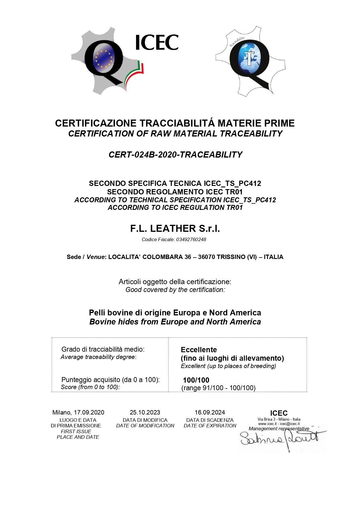
Certifications & Quality Standards for Metal Injection Molded Components



What Customers Say About Our Metal Injection Molded Components
We needed 5G micro-connector tooling held to +/-0.002 mm for a high-density board-to-board project. XUXIANG delivered on tolerance and cut our lead time by 9 days versus our previous supplier — zero rework on the first production run.
Our NEV BMS connector housings require mirror-finish EDM and strict dimensional control. XUXIANG’s ZEISS CMM reports showed 100% conformance across 2,400 metal injection molded components in the pilot batch, and they ramped to full volume in under three weeks.
For our implantable-device assembly fixtures, we cannot accept any dimensional drift. XUXIANG maintained +/-0.001 mm repeatability over six production lots, with full FAI documentation and material certificates every time. Their DFM feedback also saved us a costly redesign.
Frequently Asked Questions About Metal Injection Molded Components
What is the minimum order quantity for metal injection molded components?
How long does it take to receive metal injection molded components?
Do you charge for samples of metal injection molded components?
What tolerances can you hold on metal injection molded components?
What payment terms do you offer for metal injection molded components orders?
How do you protect my intellectual property and design files?
What material certifications do you provide with metal injection molded components?
Do you handle international shipping for metal injection molded components?
Can I get a quote for metal injection molded components within 24 hours?
The Complete Buyer’s Guide to Metal Injection Molded Components for Precision Manufacturing
Navigate the complexities of sourcing metal injection molded components with confidence. This guide delivers a proven decision framework, critical supplier evaluation criteria, and the most common procurement mistakes to avoid when selecting MIM parts for your production needs.
1. What Are Metal Injection Molded Components?
Metal injection molded components are net-shape or near-net-shape metal parts produced through a powder-metallurgy process that merges the geometric freedom of plastic injection molding with the material performance of sintered alloys. First commercialized in the 1970s, MIM bridges the gap between low-volume CNC machining and high-volume stamping, delivering complex three-dimensional features — undercuts, threads, thin walls below 0.5 mm — at tolerances typically +/-0.3 % to +/-0.5 % of nominal dimension.
The process unfolds in four sequential steps: feedstock preparation (fine metal powder mixed with thermoplastic binders), injection molding (the feedstock is shot into heated cavities to form ‘green’ parts), debinding (thermal or solvent removal of most binder), and sintering (high-temperature densification that shrinks parts 15–20 % and achieves 95–98 % theoretical density). Post-sintering, parts exhibit mechanical properties comparable to wrought or cast equivalents.
MIM is widely adopted in electronics (micro-connector housings, shielding clips), automotive sensor brackets, surgical-instrument components and industrial-automation end effectors — anywhere design complexity, material variety and production volumes from 10,000 to multi-million annually justify tooling investment.
2. Evolution and History of Metal Injection Molding Technology
Metal injection molding emerged in the early 1970s when researchers at Parmatech combined powder metallurgy with plastic injection molding to produce complex geometries impossible with conventional pressing. Commercial production began in the mid-1980s, first serving firearms (trigger assemblies, safeties) and dental orthodontics (brackets, bands), where intricate shapes and corrosion resistance justified the tooling investment.
By the late 1990s automotive and consumer electronics adopted MIM for high-volume precision hardware — turbocharger vanes, seat-belt components, smartphone hinge mechanisms and laptop latches — driven by tighter dimensional tolerances approaching ±0.3 % and expanded alloy libraries including 316L, 17-4PH and soft magnetics. Process refinements in feedstock rheology and sintering atmospheres reduced porosity below 2 % and enabled net densities above 96 %.
Since 2015 micro-MIM has scaled down feature resolution to ±0.01 mm, unlocking 5G RF-connector shields, board-to-board terminal housings and surgical micro-instruments. Today’s MIM lines integrate real-time mold monitoring and ZEISS-class CMM validation, delivering metal injection molded components with tolerances once reserved for CNC machining at a fraction of the per-piece cost.
3. Types of Metal Injection Molded Components by Application
Metal injection molded components serve five major application families, each with distinct geometry, tolerance and performance demands. Understanding these categories helps procurement teams match process capabilities to end-use requirements.
Electronics and 5G Connector Hardware
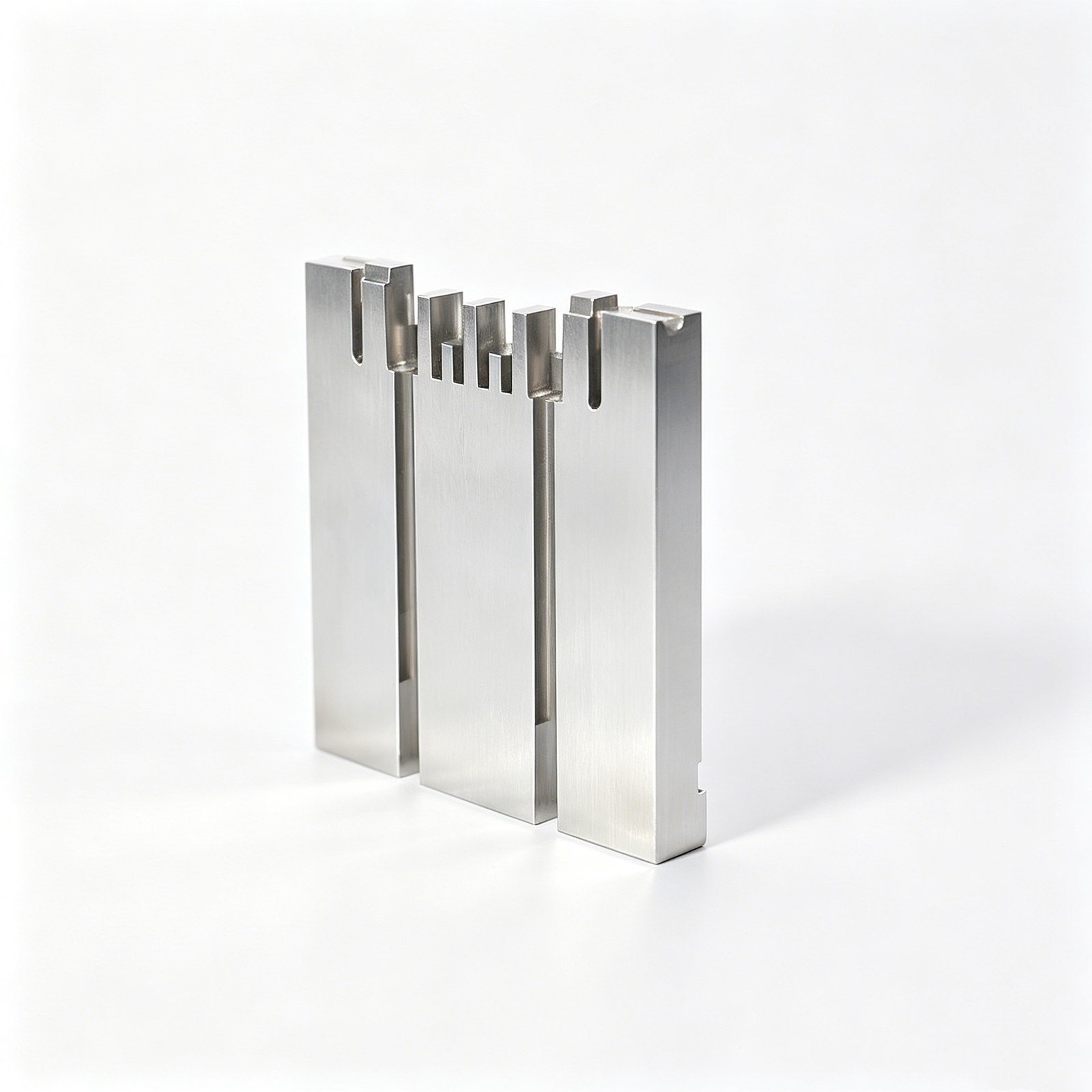
Connector pins, housings and terminal contacts dominate electronics MIM portfolios. Typical geometries include micro-pins down to 0.3 mm diameter, board-to-board housings with wall thickness ≤ 0.4 mm, and RF shields requiring +/-0.01 mm positional tolerance. Stainless 316L and 17-4PH alloys meet corrosion and spring-force specifications.
Automotive and NEV Sensor Housings
ADAS sensor brackets, BMS interconnect shells and powertrain mounting hardware require +/-0.02 mm flatness and operating ranges from -40°C to +150°C. Complex undercuts and integrated bosses reduce assembly steps; 17-4PH and low-alloy steels balance strength and cost.
Medical Instruments and Implantable Devices
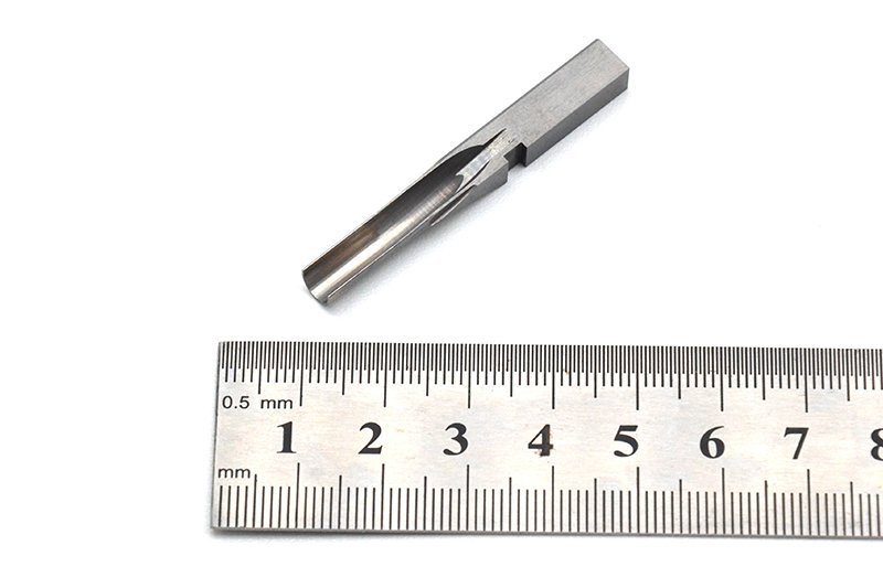
Surgical forceps jaws, orthodontic brackets and pacemaker cases demand biocompatible 316L or titanium alloys, Ra ≤ 0.8 µm surface finish, and full material traceability. Tolerances of +/-0.015 mm ensure repeatable fit in sterile assemblies.
Industrial Automation and Robotics

Gears (module 0.3–1.0), latches and end-effector fingers leverage MIM’s ability to net-shape teeth and snap features. Tolerances of +/-0.03 mm on pitch diameter and case-hardened surfaces (HRC 58–62) support 10⁶ cycle life in pick-and-place systems.
4. Materials and Alloys for Metal Injection Molded Components
MIM feedstock chemistry directly determines final component density, mechanical performance and corrosion resistance. Buyers must align alloy selection with functional requirements — strength, environment and magnetic behavior — before tooling design begins.
| Alloy Family | Density (g/cm³) | Tensile Strength (MPa) | Cost Tier | Common Uses |
|---|---|---|---|---|
| 316L Stainless | 7.9 | 480–620 | Medium | Medical implants, food equipment, marine hardware |
| 17-4PH Stainless | 7.8 | 1,000–1,200 | Medium-High | Aerospace fasteners, valve components, surgical tools |
| Low-Alloy Steel | 7.85 | 550–750 | Low | Automotive sensors, gears, structural brackets |
| M2 Tool Steel | 8.15 | 1,800–2,100 | High | Cutting inserts, wear-resistant tooling |
| D2 Tool Steel | 7.7 | 1,500–1,800 | High | Punch/die inserts, high-hardness fixtures |
| Ti-6Al-4V | 4.43 | 900–1,100 | Very High | Aerospace, biomedical implants, lightweight robotics |
| Inconel 718 | 8.2 | 1,200–1,400 | Very High | Turbine blades, high-temp exhaust, oil & gas |
| Tungsten Alloy | 17–18.5 | 700–900 | Very High | Radiation shielding, counterweights, defense |
5. Customization and Secondary Operations for Metal Injection Molded Components
Post-sintering secondary operations transform metal injection molded components into final-spec parts. While MIM achieves net-shape geometry and 95–98% density, critical tolerances, surface finish and functional performance often require CNC machining, finishing or coating.
| Finishing Method | Surface Roughness (Ra) | Corrosion Resistance | Cost Impact |
|---|---|---|---|
| Tumbling / polishing | 0.4–1.6 µm | Moderate | +5–15% |
| Passivation (stainless) | As-sintered | High | +3–8% |
| PVD coating | 0.1–0.3 µm | Very high | +15–30% |
| Electroplating (Ni, Au) | 0.2–0.5 µm | High | +10–20% |
CNC Machining for Critical Features
Sintered MIM parts shrink 15–20%, making sub-0.01 mm tolerances difficult. Post-sinter CNC machining adds threads, bores, flatness or tight positional features. XUXIANG’s ZEISS MICURA CMM verifies ±0.001 mm on machined surfaces.
Machining adds 3–5 days and 10–25% cost but ensures fit for micro-connectors, sensor housings and robotic grippers where interference or clearance is non-negotiable.
Surface Finishing and Passivation
Tumbling, vibratory polishing and passivation improve corrosion resistance and aesthetics. Passivation (ASTM A967) removes free iron from stainless MIM, extending service life in medical and automotive environments.
Finishing adds 1–3 days and 5–15% cost, depending on Ra target and batch size.
Heat Treatment, Coating and Assembly
Heat treatment boosts hardness (e.g., HRC 50+ for 17-4PH). PVD, electroplating and anodizing (titanium) add wear or corrosion layers. Press-fit inserts and laser welding enable hybrid assemblies, common in 5G connector tooling and NEV battery interconnects.
6. Key Quality and Design Considerations for Metal Injection Molded Components
Successful metal injection molded components demand rigorous design-for-manufacturing rules and multi-stage quality gates. Wall thickness uniformity, draft angles and tolerance targets directly influence green-part yield, sintering shrinkage and final mechanical properties.
Design-for-MIM Fundamentals
Maintain wall thickness between 0.5 and 6 mm with ≤ 2:1 variation across features to ensure uniform feedstock flow and predictable sintering. Apply draft angles ≥ 0.5° on vertical walls and limit undercuts; external slides or collapsible cores add cost. Tolerance capability is typically ±0.3–0.5 % of nominal dimension; tighter bands require secondary CNC or grinding.
Design choices cascade: thick-thin transitions trap voids, sharp corners elevate stress concentration, and excessive complexity reduces cavity count and raises per-part cost.
Five-Stage Quality Control Checkpoints
Green-part inspection verifies cavity fill and dimensional conformance before debinding. Debinding cycle validation tracks binder removal kinetics to prevent cracking or slumping. Sintering shrinkage control — typically 15–20 % linear — is monitored via witness coupons and process logs.
CMM verification on ZEISS or equivalent platforms confirms final geometry to ±0.001 mm, while material certification (spectral analysis, hardness, density) ensures alloy composition and mechanical performance meet datasheet values.
7. How to Choose a Metal Injection Molded Components Manufacturer
Choosing the right MIM supplier requires evaluating technical capability, quality infrastructure and operational agility. A structured audit framework protects against tolerance failure, delivery delay and hidden rework costs.
Production Capacity and Scalability
Confirm annual shot capacity, press tonnage range and multi-cavity tooling capability. Ask whether the supplier owns backup capacity or relies on subcontractors during peak demand.
A dual-factory setup — like XUXIANG’s Dongguan and Quanzhou sites — offers roughly 200 percent capacity headroom, shortening lead times by ~30 percent and enabling pilot-to-production transitions without vendor changes.
In-House Tooling and Mold-Making Capabilities
Suppliers with integrated EDM, slow-wire and CNC electrode fabrication deliver faster DFM feedback and tighter gate-to-gate tolerances. Ask to see mold-flow simulation software, electrode libraries and tool-room certifications.
XUXIANG’s Sodick and Charmilles sinker EDM, Seibu slow-wire and Beijing Jingdiao electrode CNC maintain +/-0.002 mm positioning, eliminating third-party tooling delays and version-control risk.
Material Certifications and Quality Systems
Medical-device buyers require ISO 13485; automotive OEMs mandate IATF 16949. Verify ISO 9001:2015 registration, process FMEA documentation and incoming-material spectral analysis.
XUXIANG’s five-step QC flow — spectral analysis, in-process monitoring, ZEISS MICURA CMM (0.7 µm resolution), surface-integrity checks and FAI with material certificates — ensures traceability from billet to final inspection.
Prototyping Speed and Secondary Operations
Ask for typical sampling lead times, NRE structure and whether secondary operations (heat treatment, plating, assembly) are performed in-house or outsourced. Integrated secondary ops reduce handoff delays and quality escapes.
8. Common Mistakes When Sourcing Metal Injection Molded Components
Even experienced procurement teams encounter avoidable pitfalls when sourcing metal injection molded components. Understanding these mistakes — and the engineering realities behind them — protects both timeline and budget.
Ignoring Sintering Shrinkage in Design Tolerances
MIM parts shrink 15–20% during sintering; failing to account for this in CAD tolerances leads to out-of-spec deliveries. Specify final dimensions and confirm your supplier models shrinkage compensation into the feedstock and tooling design.
XUXIANG’s DFM team reviews every design for shrinkage compatibility before production, ensuring +/- 0.002 mm class final tolerances through ZEISS MICURA CMM validation.
Specifying Incompatible Material-Geometry Combinations
Requesting 316L stainless in wall sections below 0.3 mm or complex undercuts without ejection analysis creates mold-release failures. Match alloy flow properties to part geometry and consult your supplier’s material-design matrix early.
Engineers with 10+ years of micro-connector and precision-insert experience can flag incompatibilities during quote review.
Choosing Suppliers Without Secondary-Operation Capabilities
MIM often requires CNC machining, heat treatment or plating to meet final specs. Vendors lacking in-house secondary ops add handoff delays and traceability gaps. Select partners who integrate post-sintering processes under one roof and one ISO 9001:2015 quality system.
9. Steps to Launch Your Metal Injection Molded Components Project
Launching a metal injection molded components project requires a structured procurement sequence to minimize risk and ensure dimensional and mechanical compliance. Each phase carries specific deliverables and timeline milestones that protect tooling investment and production schedules.
Define Requirements and Conduct DFM Review
Document part geometry, tolerances (e.g., ±0.05 mm), material grade (316L, 17-4PH, etc.) and annual volume before contacting suppliers. Request a design-for-MIM feasibility analysis within 3–5 business days to identify wall-thickness limits, draft angles and ejection constraints.
XUXIANG’s 10+ engineering experts deliver DFM feedback that flags tooling risks and cost drivers, helping buyers avoid post-tooling redesigns that add 4–6 weeks to launch.
Select Material, Request Quotes and Validate Samples
Shortlist 2–3 suppliers and request formal quotations with tooling cost, piece price at target volume and lead-time breakdown. Order prototype samples (typically 10–50 units) for dimensional CMM validation, mechanical testing (tensile, hardness) and environmental exposure (salt spray, thermal cycling) per application standards.
Sample turnaround averages 2–3 weeks; allocate an additional week for metrology and test reports before tooling approval.
Approve Tooling, Launch Pilot and Establish Scorecards
Sign off on tooling design and production plan, then place a pilot order (500–2,000 pieces) to validate process capability and incoming-inspection protocols. Finalize quality agreements covering FAI documentation, material certificates and ongoing supplier scorecards (on-time delivery, Cpk ≥1.33, zero-defect rate).
Pilot-to-production transition typically spans 4–6 weeks, ensuring stable supply before volume ramp.
10. Pricing and Cost Factors for Metal Injection Molded Components
Tooling investment for metal injection molded components typically ranges from $5,000 to $50,000 per cavity, depending on part complexity and feature density. This fixed cost is amortized across production volume, making MIM economically attractive above 10,000 pieces. Material costs — powder feedstock blended with polymer binder — add $8–$25 per kilogram, while debinding and sintering cycles contribute $0.15–$0.80 per part depending on furnace throughput.
At 1,000-piece runs, unit costs remain high ($8–$15) because tooling amortization dominates; CNC machining or precision casting may be more cost-effective. Beyond 50,000 pieces, unit prices drop to $0.50–$3.00, and MIM begins to outperform traditional machining on complex geometries. Secondary operations — heat treatment, surface finishing, precision grinding — add $0.10–$1.50 per part but are often unavoidable for tight-tolerance connector pins or sensor housings.
Lead times compress with volume: prototype tooling ships in 3–4 weeks, production molds in 5–7 weeks, and first articles follow 2–3 weeks later, roughly 30% faster than conventional precision-machining workflows.
| Quantity Tier | Unit Price (USD) | Tooling Allocation | Typical Lead Time |
|---|---|---|---|
| 1,000 pcs | $8.00–$15.00 | $5.00–$10.00/pc | 6–8 weeks |
| 10,000 pcs | $2.50–$6.00 | $0.50–$1.50/pc | 7–9 weeks |
| 100,000 pcs | $0.80–$2.50 | $0.05–$0.20/pc | 8–10 weeks |
| 500,000 pcs | $0.50–$1.50 | $0.01–$0.05/pc | 10–12 weeks |
Ready to Source Precision Metal Injection Molded Components?
Send your drawings today and receive a detailed quote within 24 hours — backed by dual-factory capacity and ISO 9001:2015 quality.