By Jenny
Angularity measurement for mold components starts by simulating the drawing datums, then evaluating the entire specified inclined face against a linear tolerance zone set at the basic angle. A reported angle by itself is not enough. Buyers should approve the datum setup, measured-face coverage, and reporting logic before deciding whether a fixture-and-indicator method or CMM evaluation is appropriate.
What angularity controls on an inclined mold face
For the planar-face case, angularity controls the orientation and form of a surface relative to a datum at a drawing-defined basic angle. The acceptance zone is two parallel planes oriented at that basic angle from the datum; the controlled surface must lie within that zone. The tolerance value is a linear distance, expressed in the drawing’s units, rather than a plus/minus angular dimension. GD&T Basics explains the planar angularity zone and its linear tolerance value.
That distinction changes a buyer’s review. A report that says an inclined face is “at the correct angle” may describe an angle fit, but it does not necessarily demonstrate that all relevant points on the real face fit inside the required zone. An inclined face can have an acceptable average slope while local high and low areas, edge roll, or a bowed condition prevent the full surface from meeting angularity.
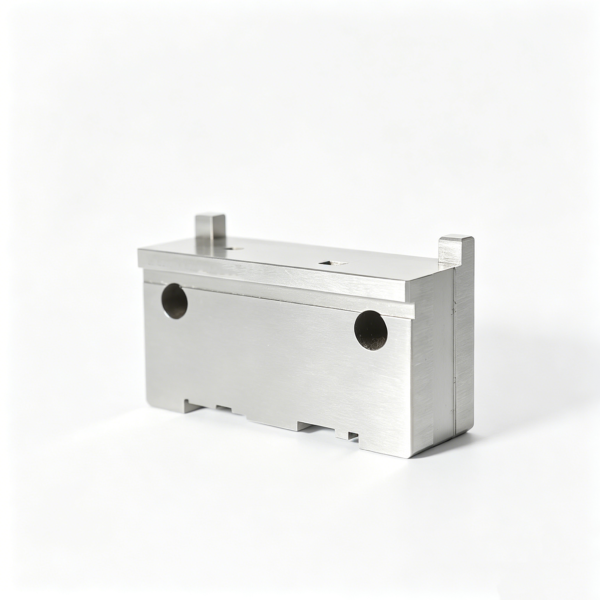
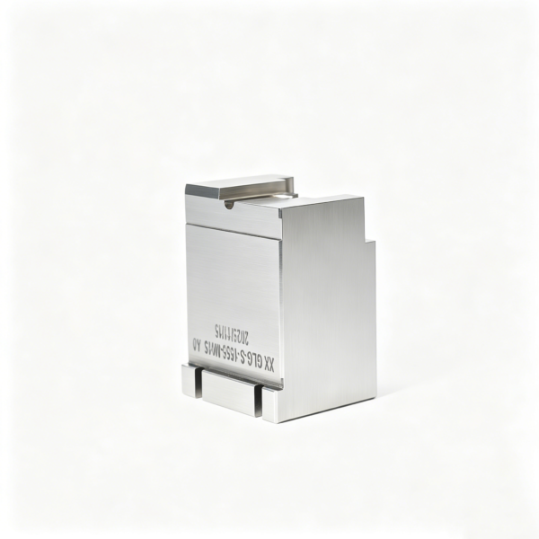
In mold work, this matters when an inclined contact, release, guiding, or wedge-related face must act predictably relative to the component’s functional seating surface. The drawing—not a photo, product category, or informal shop convention—defines what is controlled. A component may be associated with Lifters & Angle Lifters, for example, yet its inspection requirement still depends on the specific feature control frame, basic angle, datum references, and controlled face shown on the approved drawing.
Angularity is an orientation control. It does not locate the face in space and does not establish feature size. If the design also needs the inclined face to begin at a particular distance from another feature, or needs its boundary to sit at a defined location, those needs require their own drawing controls. Treating angularity as a substitute for location is a common approval mistake. GD&T Basics likewise distinguishes angularity’s orientation role from location control.
Read the callout before selecting a measurement method
A useful review begins with four questions.
First, identify the controlled feature. This article addresses a planar inclined face, not the axis of a hole, pin, or a midplane of a feature of size. Those applications may use different tolerance-zone shapes and measurement logic.
Second, identify the datum feature or datum system. The datum label is not merely a note on the drawing. It establishes the reference from which the basic orientation is constructed. If the part is seated on an unrelated convenient surface, the result may be repeatable but unrelated to the requirement.
Third, identify the basic angle. A boxed or otherwise basic angular value defines the theoretically exact orientation of the angularity zone. It is not an allowable plus/minus production angle.
Fourth, identify the boundaries of the face to be evaluated. A narrow usable strip, a full machined plane, a relieved area, and a face interrupted by a pocket do not present the same coverage question. Buyers should not leave that decision to an unstated interpretation after machining is complete.
Datum setup is the measurement, not a preliminary chore
A stable datum setup starts with the datum feature actually named by the drawing. For a primary planar datum, the inspection arrangement needs to simulate the intended contact relationship without allowing incidental burrs, damage, or unsupported overhang to dictate the result. The choice of supports, clamps, and contact areas should be recorded because each can influence how the component seats.
For a datum system, the order of precedence matters. The primary datum establishes the first orientation; secondary and tertiary datums then constrain the remaining degrees of freedom only as the drawing calls for. Adding an uncalled-for stop or clamping a side face tightly enough to reorient the part can hide the condition that inspection is meant to reveal.
A datum plane should be established from suitable points or an appropriate datum simulation strategy, not inferred from a single contact. KEYENCE describes CMM evaluation by sampling multiple points on the datum plane and measuring the target plane after the datum is established; it also notes that a datum system can be handled similarly. KEYENCE, “Measuring Angularity.”
The controlled inclined face deserves the same discipline. Measure the surface area that the callout controls, not only a visually clean line near its center. If machining leaves a narrow land alongside a relieved area, define whether the land alone is the controlled feature. If the face is interrupted, identify the usable patches before inspection begins. Clear coverage rules prevent a favorable but unrepresentative scan path from becoming the de facto acceptance standard.
Separate angularity result, angle-fit residual, form, and coverage
These four ideas are often blended into one vague statement that a face is “good.” They answer different questions.
Angularity result
This is the calculated or indicated result against the drawing’s datum-derived linear tolerance zone at the stated basic angle. It is the acceptance result for the angularity callout when the setup and coverage are valid.
Angle-fit residual
An angle fit can estimate the slope that best represents measured data and show how data deviate from that fitted slope. It is useful for diagnosis: it may suggest a gradual machining tilt or a setup issue. But a best-fit angle is not automatically the drawing’s datum-related angularity evaluation. It can mask a datum shift or distribute error in a way that does not reflect the specified zone.
Form
For a planar surface, angularity’s two-plane zone also constrains the surface’s form within that oriented zone. A face can therefore fail even when its overall slope appears correct. Local waviness, a corner high point, or an edge condition may matter if it lies within the controlled area. GD&T Basics describes surface angularity as controlling both orientation and form through the two parallel planes.
Coverage
Coverage is the extent and pattern of sampling over the controlled face. It is not the same as collecting many points in one small region. A defensible plan reaches the locations most likely to reveal the actual condition: near relevant boundaries, across the face, and around interrupted or transition areas where applicable. The exact point pattern should suit the geometry and approved inspection plan rather than follow a generic count.
A useful report names these items separately. It should state the drawing revision, controlled feature, datums simulated, basic angle, evaluation area, method, result in drawing units, and any exclusions. Where diagnostic information is included, label it as diagnostic rather than presenting it as the acceptance criterion.
Choosing a qualified fixture and indicator or CMM evaluation
Neither route is universally superior. The right choice depends on the geometry, access, datum simulation, required documentation, and whether the method can evaluate the specified surface rather than a convenient proxy.
A qualified fixture-and-indicator approach can be a practical option for a planar inclined face when the component can be seated reliably on its simulated datum and the fixture establishes the required basic orientation. The inspection team then traverses the relevant face relative to that reference. The method should account for fixture qualification, part seating, indicator travel direction, and meaningful surface coverage.
A conventional arrangement may use an angle plate, support, and dial indicator. KEYENCE notes that such setups can require time to align the target, plate, and related tooling, and can be difficult when the component cannot be fixed appropriately. KEYENCE, “Measuring Angularity.” For buyers, the implication is simple: ask to see the setup logic, not merely the final indicator range.
CMM evaluation can be preferable when the datum system, face boundaries, or access make a physical fixture difficult to interpret consistently. It can establish datums from measured features and evaluate target-plane data in a documented alignment. Yet a CMM result is only as relevant as its datum construction, measured region, probing strategy, and evaluation routine. A dense cloud over the wrong region does not improve approval confidence.
Use this decision framework:
- Choose a qualified fixture-and-indicator route when the drawing datum can be simulated physically, the face is accessible for a meaningful traverse, and the fixture provides a reviewable representation of the basic orientation.
- Consider CMM evaluation when multiple datums need to be established, the part cannot be stably or accessibly positioned on a fixture, or the controlled face needs broader mapped coverage.
- Use both approaches when the contract or risk level calls for a correlation exercise. Compare the agreed setup and reporting definitions, rather than assuming the instruments must deliver interchangeable numbers.
- Escalate before release when the face boundary, datum-contact area, or interpretation of a relieved region is unclear. The remedy is an engineering clarification, not a more elaborate measurement report.
A worked approval example for one planar inclined face
In this hypothetical example, consider a mold insert with one planar inclined face controlled by an angularity feature control frame relative to datum A at a stated basic angle. The drawing identifies the face, the basic angle, the linear tolerance, and the relevant units.
The review team first agrees which physical surface simulates datum A and which portion of the inclined face is functional and controlled. They decide whether a fixture can seat the insert on A without forcing it into a different orientation. If a fixture is used, it is arranged to represent the basic angle rather than simply to make the face look level. If a CMM is used, the program establishes datum A from the agreed datum area and evaluates the agreed face area in that alignment.
The report then presents the angularity result against the specified zone. It separately records the actual coverage and any intentionally excluded non-feature area. If a best-fit angle or a local map is included, it is retained as diagnostic context. No one uses the best-fit angle alone to override an out-of-zone surface condition, and no one treats angularity as proof that the inclined face begins at the required location.
Numbered approval workflow for buyers and engineering teams
- Freeze the controlling drawing revision and identify the planar inclined face, basic angle, datum references, units, and angularity tolerance.
- Mark the functional area of the face and the usable datum-contact area. Resolve pockets, reliefs, blends, damaged edges, and coating boundaries before inspection.
- Select an inspection route based on stable datum simulation and access: qualified fixture with indicator, CMM evaluation, or an agreed comparison plan.
- Review the setup before measurement. Confirm how the part is seated, supported, clamped, and prevented from shifting without being distorted or reoriented.
- Approve a coverage plan that represents the controlled face, including boundary and cross-face locations appropriate to the geometry.
- Evaluate angularity in the datum-derived alignment and report the result in the drawing’s units.
- Review diagnostics separately from acceptance: angle-fit residual, local form behavior, coverage record, and any excluded areas.
- Release, rework, or request engineering disposition using the documented drawing requirement—not an informal nominal-angle comparison.
Compact measurement-readiness checklist
Before approving a measurement plan, confirm:
- The exact controlled planar face is identified.
- The datum feature and datum precedence match the drawing.
- The basic angle is used to orient the tolerance zone.
- The report uses the drawing’s linear units.
- The fixture or program explains datum simulation and part restraint.
- Coverage reaches the agreed functional area, not only an easy measurement line.
- Acceptance angularity, angle-fit diagnostics, form observations, and location requirements are not conflated.
- The report identifies drawing revision, method, exclusions, and result.
Buyer FAQ
Is a plus/minus angle reading enough to approve angularity?
No. A plus/minus angle comparison may be useful diagnostic information, but planar angularity is evaluated as a linear zone oriented at the drawing’s basic angle from the datum.
Does passing angularity prove the inclined face is in the correct location?
No. Angularity controls orientation, not location. Review location dimensions or separate GD&T controls when the face boundary or intersection must be positioned.
Can an indicator method be used for a planar inclined face?
It can be considered when the part can be reliably datum-seated and the fixture establishes the required orientation. The planned traverse and coverage should be reviewed before it becomes an acceptance method.
Is a CMM automatically the better option?
No. It may handle complex datum setups or access well, but its alignment, measurement area, and reporting rules still need to match the drawing requirement.
Why does surface coverage matter if the reported angle is correct?
A limited path can miss local form variation or edge behavior. Angularity concerns the controlled surface within its zone, so the measured area must represent that surface.
For an inclined-face drawing review or component discussion, discuss your project with XUXIANG.