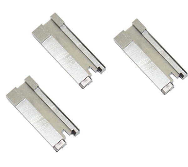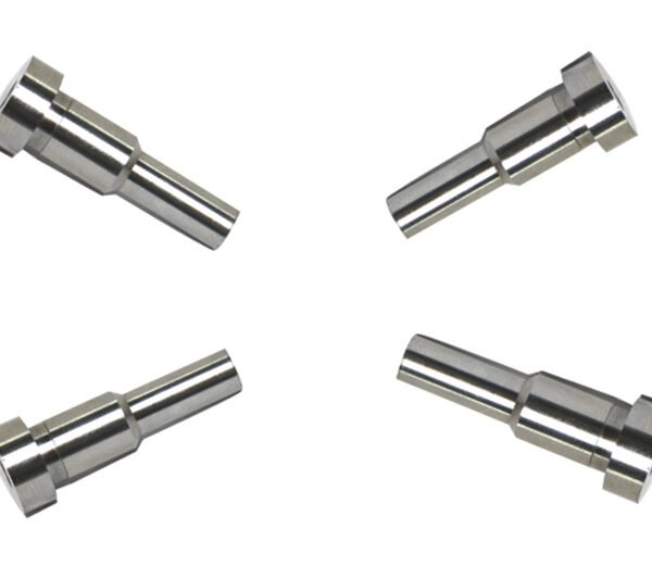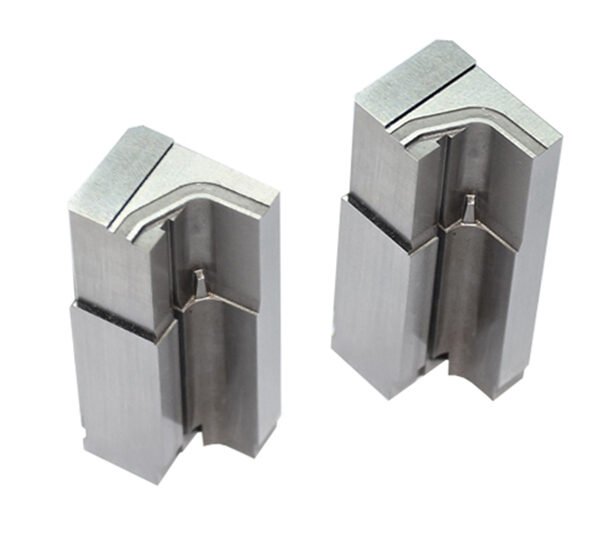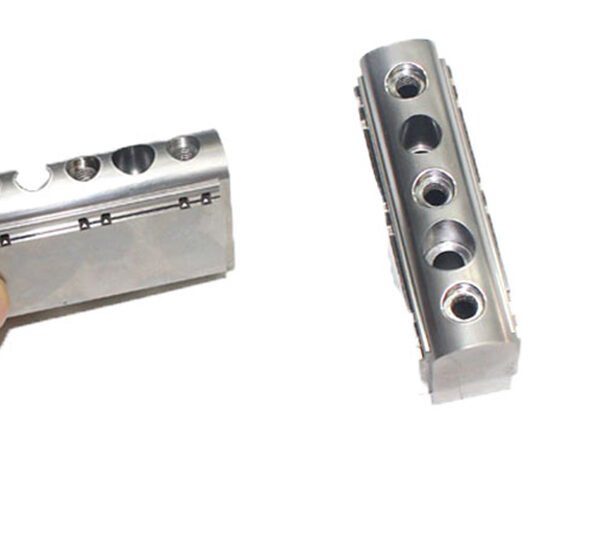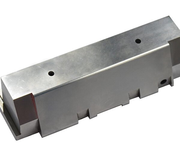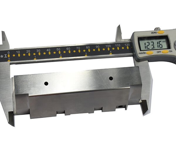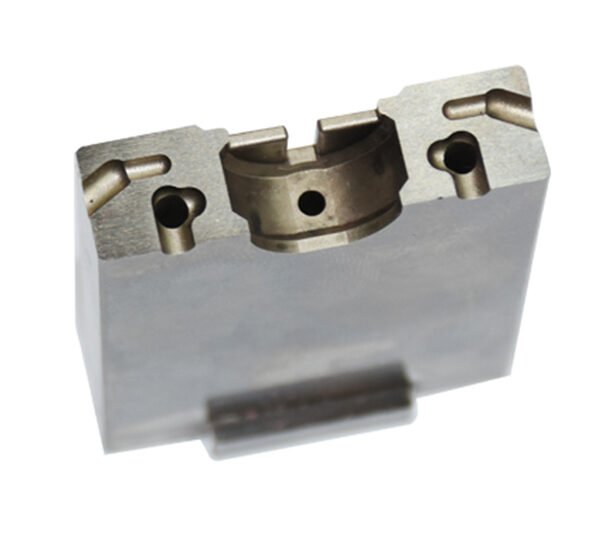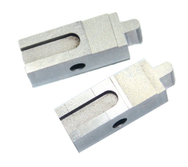
Burr acceptance for precision mold components should be decided feature by feature, not by a blanket “burr-free” instruction. The drawing or approved inspection plan should define the controlled edges, allowable condition, inspection method, reference surfaces, and disposition path. This protects mating function and safe handling without unintentionally rounding shutoffs, sealing lands, or delicate working geometry.
Start with a functional definition of the edge condition
A burr is unintended material that remains or is displaced at an edge after an operation such as milling, drilling, turning, grinding or cutting. It may appear as a raised lip, feather, sliver, rollover, or sharp projection. In metalworking, burr size may be described by its height or base thickness; more importantly for a buyer, its location and attachment condition determine whether it can interfere with the next operation. KEYENCE’s burr measurement overview also notes that out-of-range burrs can create fitting, joining, and connection problems.
Do not use “burr” as a catch-all for every edge concern. A sound acceptance package separates these conditions:
- Burr: unwanted raised or displaced material at an edge.
- Intentional sharp edge: a deliberately retained intersection that performs a function, such as a cutting, locating, shutoff, or profile-defining edge. It is not automatically a defect.
- Chamfer or radius: a deliberately specified geometric transition. It has its own drawing definition and dimensional verification path; it is not merely evidence that a burr was removed.
- Surface roughness: the texture of a surface area. It can influence friction, sealing, appearance, and measurement response, but it does not define edge projection.
- Recast layer: material that melted and then resolidified at a worked surface. Its evaluation, where relevant, is separate from visual burr acceptance.
This distinction matters because an indiscriminate edge-rounding instruction can solve a handling issue while changing the geometry that makes the component work. A burr-removal operation should therefore be evaluated against the intended edge condition, not against a vague preference for smoother-looking parts.
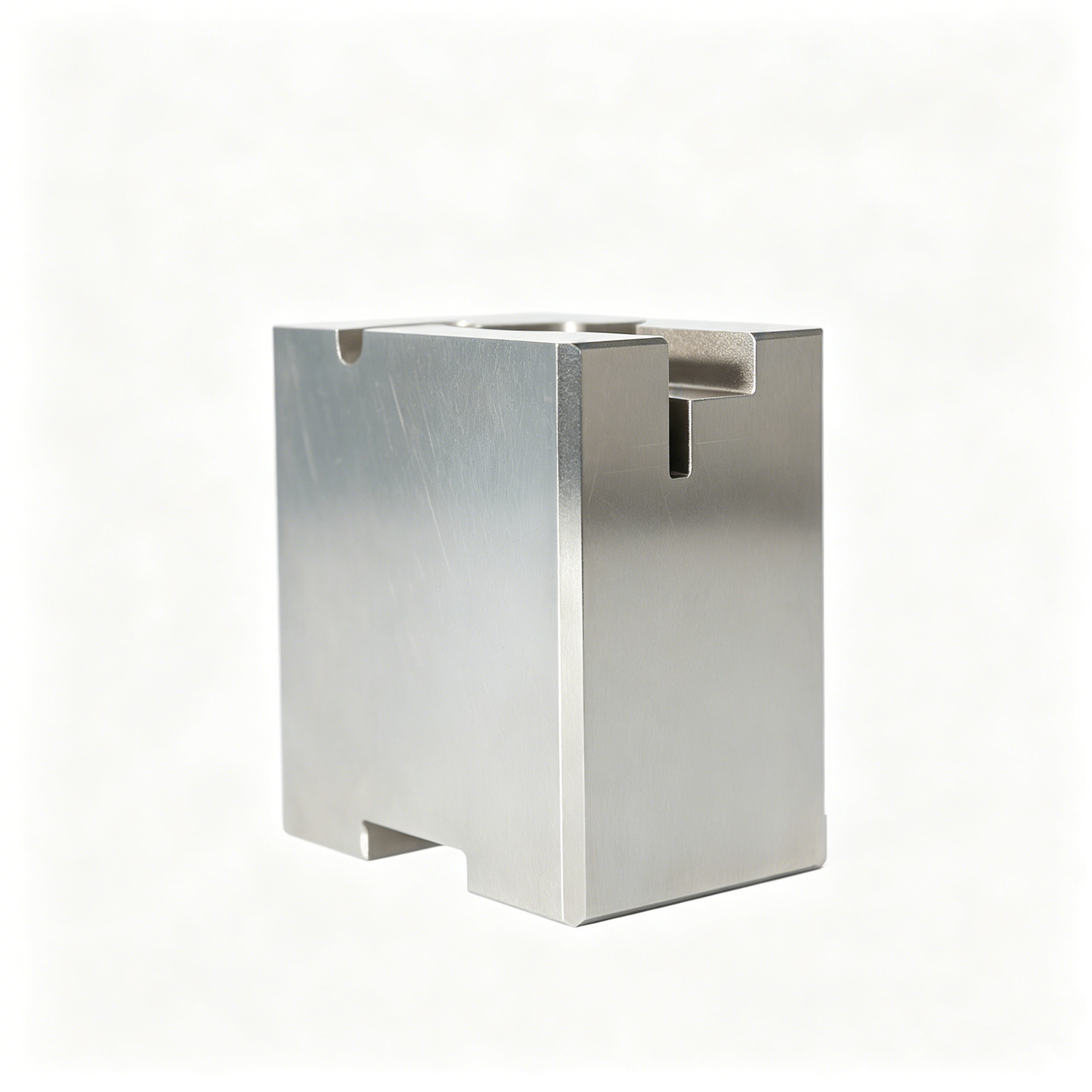
Decide which edges need the strongest control
The same visible projection has different consequences depending on where it sits. Build an inspection map that names the features and assigns each a functional class before deciding the acceptance limit or method.
Critical functional boundaries
Give explicit drawing or project-level direction to edges that affect shutoff, sealing, location, movement, electrical contact, or a close mating relationship. Typical examples include:
- shutoff boundaries on cores, inserts, slides, and mating tooling surfaces;
- sealing lands and surfaces that must meet without an unintended gap;
- locating faces, guide interfaces, datum-related edges, and close-fit bores;
- slender pins, ribs, walls, and fine projections that could be weakened or reshaped by aggressive finishing;
- edges adjacent to cavities, vents, gates, or formed parting features where geometry influences the molded result;
- contact faces that could scratch, snag, bind, or carry loose debris into an assembly.
For these areas, the buyer should state whether the edge is to remain sharp, receive a defined chamfer or radius, or be controlled only for an agreed burr condition. “Break all edges” is usually too broad when the part contains functional intersections. It can obscure which edges were meant to change and which were meant to remain intact.
Controlled but lower-risk boundaries
Non-mating external edges, handling edges, and cosmetic perimeter edges can still need a defined condition. The priority is often safe handling and removal of loose material, provided the treatment does not alter a nearby datum, engraved detail, hole entrance, or visible profile. Put these areas on the inspection map too; otherwise, inspectors are forced to infer what “acceptable” means from appearance alone.
Why loose particles deserve their own line item
A burr can be attached yet tolerable under an agreed condition, while a detached sliver can contaminate an assembly, obstruct a small passage, or scratch a mating surface. Treat loose-particle concerns separately from burr height or projection. The inspection plan should say how the part is cleaned, which areas are checked after cleaning, and how the final condition is documented. This prevents a dimensional measurement from being mistaken for a cleanliness decision.
Use a decision framework before writing the callout
A practical approval decision asks four questions in order.
First: what must the edge do? Identify whether it seals, locates, shears, mates, clears another component, or is handled by an operator. If the function requires a sharp intersection, preserve it unless the drawing changes it.
Second: what failure could an unwanted projection cause? Consider interference, damage to a mating face, unreliable seating, snagging, particle release, or handling risk. Do not assume that every edge carries the same risk simply because the component has close dimensional tolerances.
Third: what is actually controlled? Separate burr projection, burr location, loose debris, intentional edge geometry, and dimensional tolerance. A burr at a bore exit, for example, may need a different requirement from an outer handling edge. A chamfer, if required, should be called out as a chamfer rather than accepted through a visual “deburred” note.
Fourth: can the chosen method see and measure it reliably? An accessible outer edge may be screened visually, while a recessed slot, small cross-hole, or functional profile may need magnification, a calibrated optical method, a suitable dimensional method, or another agreed approach. The answer depends on access, the agreed reference plane, feature orientation, and the uncertainty appropriate to the acceptance limit.
This framework produces an inspection plan that is testable and auditable without pretending that one inspection technology or one cosmetic standard suits every component.
Write edge requirements that a supplier and inspector can use
A useful requirement identifies the edge, intended condition, acceptance criterion, and verification approach. It should also state what happens when the condition cannot be resolved by normal finishing without affecting function.
For an intentionally broken edge, specify the intended chamfer or radius on the relevant feature and make it subject to the appropriate dimensional controls. For a retained sharp edge, identify the boundary clearly and define any allowable unintended projection separately. For a general handling edge, state the agreed condition and include a loose-material expectation if it matters to assembly.
Avoid ambiguous acceptance phrases such as “remove all burrs” when the part has critical sharp geometry. They invite inconsistent judgment: one operator may lightly finish an edge, while another may materially alter it. Similarly, avoid treating surface roughness as proof that an edge is acceptable. A smooth face can end in an unwanted lip, and a controlled edge break can exist on a surface with a separately specified texture.
The buyer should also decide whether the first approved article establishes visual reference examples. Reference samples can support repeatable decisions, but they should be tied to the drawing and inspection map rather than replace them. A photo alone is insufficient unless it identifies the feature, orientation, scale or reference, and the approved disposition.
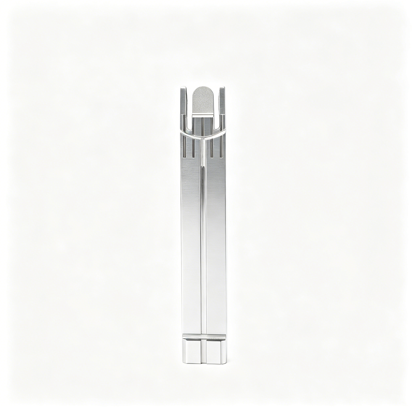
Match inspection to the question being asked
Visual inspection under stable lighting and magnification is valuable for finding edge reflections, burr location, shape, and obvious loose material. The microscope manufacturer’s guide recommends examining edges under stable lighting, rotating components to reveal edge reflections, and using documented criteria; it also distinguishes screening before deburring from verification after it. HS Microscope supports these qualitative inspection practices.
Microscope screening is not automatically a calibrated measurement. It is appropriate when the approved question is whether a feature shows a visible burr, whether an edge condition resembles the approved reference, or whether debris is present in accessible areas. Its limits include access, focus, lighting direction, operator interpretation, and the lack of a defensible dimensional reference unless the setup is calibrated for that use.
When acceptance depends on a measurable projection or edge transition, agree a calibrated method and measurement setup. Define the datum or reference plane from which the feature is evaluated, the view or section used, how the part is fixtured, and the reporting resolution and uncertainty needed for the approved criterion. A method that cannot access the relevant edge or establish the reference surface should not be used as the sole release evidence.
Profile-only sampling can miss a localized maximum if the selected line is not where the burr occurs. KEYENCE describes the challenge of evaluating burrs with conventional profile measurement and presents area-based 3D shape evaluation as a way to examine broader geometry and compare data with tolerance information. KEYENCE’s application note is useful as a qualitative reason to plan coverage, not as a mandate to use a particular instrument.
For buyers, the practical question is not “Which machine is best?” It is “Does this method reliably cover the risk area and produce evidence that corresponds to the agreed requirement?” A high-value or difficult-to-access feature may justify more complete coverage; a low-risk external edge may only need a defined visual screen. All limits and method choices remain drawing-, customer-, or project-agreed.
Approval workflow for burr acceptance
- Classify every relevant edge. Mark critical shutoff, sealing, mating, locating, slender, handling, and cosmetic boundaries on an inspection map. Name the feature and identify the functional consequence of an unintended projection.
- Define the intended geometry. For each class, state whether the design calls for a retained sharp edge, a drawing-defined chamfer or radius, or an agreed burr condition. Keep surface roughness and recast-layer requirements in their own controls where applicable.
- Set acceptance evidence before production approval. Agree the criterion, inspection coverage, viewing or measurement orientation, reference plane where needed, sampling or full-coverage decision, and the record format. Do not leave these choices for shipment inspection.
- Screen before any corrective work. Inspect representative risk areas to understand burr location and process behavior. Record the feature, condition, photo scale or measurement reference, and whether the condition is attached material or loose debris.
- Use controlled deburring only where permitted. Select a process that preserves the specified geometry and does not hand-rub sharp edges. If removal could alter a critical intersection, stop and request an engineering disposition rather than making an undocumented change.
- Clean and reinspect. Verify that deburring has not left particles or damaged a functional edge. Reinspect the same mapped areas with the agreed method, rather than assuming the operation resolved every location.
- Approve exceptions before shipment. Any departure from the drawing or agreed inspection plan needs documented customer or project approval before release. The record should identify the part, revision, feature, observed condition, evaluation evidence, proposed disposition, and approval status.
Compact pre-approval check
Before releasing a purchase order or first article, confirm that the package answers these points:
- Are critical edges identified by feature rather than covered by one global note?
- Does each edge state sharp, chamfered/radiused, or burr-controlled intent?
- Are burr projection, location, loose particles, and dimensional tolerance treated separately?
- Is the inspection method capable of accessing the edge and using the agreed reference?
- Will the record show orientation, photo scale or measurement reference, and final disposition?
- Is there a defined path for a condition that cannot be corrected without changing function?
These questions are especially useful when a component moves between machining, finishing, cleaning, assembly, and receiving inspection, where a vague “deburred” status can otherwise lose its meaning.
FAQ
What is a burr on a machined part?
It is unintended raised or displaced material at an edge created by an operation. Its acceptance depends on the feature’s function, the agreed criterion, and whether it presents an interference, damage, particle, or handling risk.
What is the callout for an edge break?
Use a drawing-defined chamfer or radius when a geometric edge break is intended. For burr control, identify the affected edge or feature and state the project-agreed acceptance condition and inspection method. Do not rely on a broad phrase where critical sharp edges must remain unchanged.
What is the process of removing burrs called?
It is commonly called deburring. For precision mold components, deburring should be a controlled operation followed by cleaning and reinspection, because removal can affect a functional edge as well as the unwanted material.
How do you measure edge breaks?
First distinguish a specified chamfer or radius from an unintended burr. Measure the specified geometry using an agreed calibrated method and reference scheme. Use visual magnification for screening when appropriate, but select a dimensional method when acceptance depends on quantified geometry.
Can a part pass dimensional inspection but fail burr acceptance?
Yes. Dimensional tolerance, burr projection, edge intent, and loose-particle condition are separate decisions. A part can meet nominal dimensions while an unwanted edge condition still threatens assembly, sealing, mating, or safe handling.
For a drawing-specific edge map and inspection evidence plan, discuss a drawing and inspection plan with XUXIANG. For component context, see precision mold components and the related guidance on surface-finish specifications.