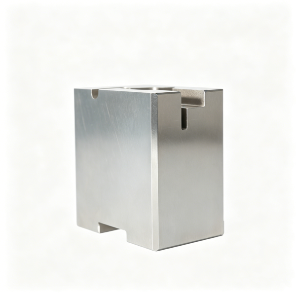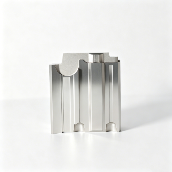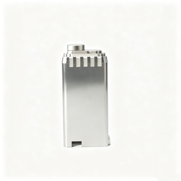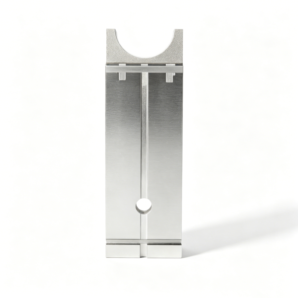
Datum alignment for mold component inspection means evaluating the part in the drawing-controlled reference frame, not simply placing it where it is convenient on a CMM. Buyers should approve the datum features, restraint method, alignment logic, and reporting record before using results for acceptance. That protects functional location and orientation requirements from being hidden by setup choices.
For a mold insert, core, slide, cavity component, or precision-machined fixture element, inspection begins before a probe takes a point. The released drawing establishes what must be evaluated. The physical part, the fixture, the CMM program, and the report must all preserve that intent.
This matters because two competent inspectors can obtain different values from the same raw measurement data when they use different alignments. A difference is not automatically evidence that either result is wrong. It is evidence that the buyer needs to identify which setup represents the acceptance condition defined by the drawing.
XUXIANG buyers can use the following framework when reviewing an inspection plan alongside the drawing, CAD model, and applicable acceptance requirements.
Start with the distinction between a feature and a datum
A datum feature is an actual part feature selected to establish a reference: for example, a mounting face, a bore, a slot, or a pair of datum targets. A datum itself is the theoretically exact reference derived from that feature through a specified establishment method. KEYENCE describes a datum as a plane, line, or point used as a reference and distinguishes the real datum feature from the simulated feature that contacts it, such as a surface plate, gauge, or mandrel. KEYENCE: What Are Datums?
That distinction is practical. A real face may contain texture, local damage, residual burrs, or form variation. The CMM does not make the real face perfect; it derives an idealized plane, axis, center plane, or other reference according to the programmed and approved method. The fixture must support that derivation without accidentally redefining it.
A datum reference system is the ordered set of datum references used by a particular geometric tolerance. It may use one or more datums as specified, including datums established from combined feature groups. It need not be three planar surfaces. A cylindrical datum feature may establish an axis; datum targets may establish contact locations; a center plane may be appropriate for a feature of size. The drawing, not a customary A-B-C template, determines the reference system.
Read the feature control frame before choosing an alignment
A feature-control frame communicates the geometric characteristic, tolerance, and any datum references or modifiers that govern evaluation. When several datums are listed, their position in the frame expresses precedence from left to right, according to KEYENCE’s overview. KEYENCE: Feature Control Frame
Do not infer precedence from the letters alone. “A,” “B,” and “C” are datum labels, not a universal declaration that A must always be primary. A callout referring to B|A, for example, has a different sequence from one referring to A|B. Nor does every dimension or form requirement require a datum reference. A flatness requirement, for instance, is evaluated against the requirement shown rather than automatically against a separate datum system.
Before approving a CMM setup, identify each acceptance characteristic and ask:
- Which drawing revision controls this result?
- What feature-control frame, basic dimensions, notes, and CAD authority apply?
- Which datum references govern this particular feature?
- Is the feature evaluated in a free, restrained, assembled, or otherwise specified state?
- Do material-boundary modifiers, datum targets, or datum-shift conditions affect datum establishment?
- Does the drawing leave an ambiguity that must be resolved by design authority?
The metrology team should not cure an ambiguous datum target, restraint condition, or modifier by selecting a convenient program option. Obtain a written interpretation from the responsible drawing authority and retain it with the approved inspection basis.
Separate locating and holding from evaluating
A fixture has two related but distinct jobs: safely locating the component and holding it stable during measurement. Neither job automatically makes every contact point an evaluation datum.
A locating feature may be used only to place the part repeatably enough for probing. A clamp may exist solely to prevent movement. A support may prevent sag but be outside the drawing’s datum scheme. Conversely, a drawing datum may need to be probed and mathematically established even if it is not the feature against which a clamp bears.
This distinction is especially important for thin inserts, long slides, relieved cores, or parts with polished functional surfaces. A clamp that pulls a component onto supports can alter its free-state shape or orientation. Excess force can conceal a condition that matters in use; insufficient restraint can let the part move during probing. The buyer should ask for the fixture concept, points of support, clamping direction, contact material, and the rationale for each restraint.
A useful fixture review asks four questions:
- Does the fixture provide access to all required datum and inspection features?
- Does it prevent movement without imposing a condition the drawing does not call for?
- Are contact surfaces clean and protected from burrs, chips, oil, or local damage?
- Can the part be removed and reloaded without relying on an operator’s visual repositioning?
If an acceptance setup needs specialized restraint, define that restraint explicitly. A report marked merely “fixtured” does not tell a future reviewer where the part was supported, how it was clamped, or whether the reported condition represents functional use.
Machine coordinates are not the drawing-controlled frame
CMM machine coordinates describe the instrument’s own axes. Fixture coordinates can describe the pallet, baseplate, or nest. CAD coordinates describe model geometry. These coordinate systems are useful operational references, but none becomes the acceptance frame merely because it is available.
The acceptance frame is the frame established from the drawing’s stated datums and rules for the specific characteristic. A program may begin with a rough alignment to avoid collisions, then establish a final datum alignment for evaluation. That rough alignment is operational. It must not be confused with the final evaluation alignment.
For approval, require the report or program record to state the final alignment name and the datum features used. If the program calculates a transformation after probing, retain enough information to identify its method and software version. This makes later comparison possible when a fixture, probe qualification state, CAD revision, or algorithm changes.
Best-fit alignment has a valid role, but not a free pass
Unrestricted best-fit aligns measured points to nominal geometry by minimizing overall discrepancy. It is useful for diagnostic CAD comparison: it can show broad deformation, machining stock distribution, or where a complex freeform surface differs from nominal without first forcing the part into a datum frame.
It is not automatically an acceptance alignment for a datum-controlled callout. If an unrestricted best-fit is allowed to rotate or translate the part freely, it can reduce apparent location or orientation error that the drawing intends to expose. A reported pass under that setup may therefore answer a different question than the feature-control frame asks.
Best-fit is not categorically invalid. It can be constrained and may be appropriate where the released requirement permits it, where a characteristic lacks usable datum features, or for a separately labeled diagnostic comparison. MSP describes best-fit as an approach for parts without datum features or parts needing finishing to size, based on an overall alignment from measured points; its discussion is specific to its own software and machining context. MSP: How to create an accurate Best Fit alignment
When both views are useful, request the same raw measurement data evaluated under clearly labeled alignments. For example:
- Drawing-datum alignment: the acceptance result for a datum-referenced requirement.
- Constrained best-fit: a defined supplementary evaluation whose retained constraints are stated.
- Unrestricted best-fit: a diagnostic model comparison, clearly excluded from acceptance unless the requirement authorizes it.
That approach makes disagreement visible rather than letting a favorable transformation quietly replace the approved acceptance basis.
Approval workflow for component inspection
- Freeze the governing inputs. Identify the released drawing revision, relevant CAD revision, applicable notes, and the characteristics to be accepted. Separate informational dimensions from acceptance characteristics.
- Map each characteristic to its reference system. Record the datum references as they appear in its feature-control frame. Note any datum targets, feature simulators, modifiers, free-state or restrained-state requirements, and unresolved questions.
- Review the part condition. Clean the proposed datum and contact surfaces. Inspect for burrs, chips, contamination, handling marks, and damage that could change seating or probing. Document any condition that prevents normal datum establishment.
- Approve the fixture and restraint approach. Define supports, locators, clamps, contact surfaces, loading orientation, and intended force direction. Check that the arrangement does not block required access or impose unapproved distortion.
- Define representative measurement coverage. Select probing or scanning coverage appropriate to the actual feature and requirement. Specify which areas, patterns, cavities, or interfaces are represented. Do not substitute an arbitrary minimum point count for an engineering strategy.
- Program and identify the alignment. Preserve the sequence used for pre-alignment, datum establishment, and feature evaluation. Record the alignment type, algorithm where relevant, CMM program revision, inspection software version, and applicable CAD/drawing revisions.
- Run a reload check. Remove and reload the component under the documented fixture method, then compare results according to the approved plan. A reload check tests the setup’s sensitivity to normal handling; it does not replace the defined measurement strategy.
- Issue a decision-ready report. State the part identification, revision status, condition, setup, final evaluation alignment, datum references, and result disposition. Keep supplementary diagnostic views distinct from acceptance results.
- Escalate disagreement without rewriting the evidence. If the supplier, buyer, or third party obtains a material difference, compare the released drawing, raw data, datum construction, fixture restraint, feature extraction, alignment type, and program/software records. The remedy is a documented technical disposition or drawing-authority clarification—not changing the approved drawing simply to make a result pass.
When a result should be held for clarification
Place a result on hold rather than forcing a pass/fail decision when the datum scheme cannot be established as specified, the part cannot seat because of a burr or damaged contact, the fixture changes part form without an approved restrained condition, or the drawing does not resolve a meaningful interpretation question.
Likewise, hold a comparison when teams have used different transformations but have not established whether both reports are evaluating the same drawing requirement. A best-fit CAD deviation map may still aid troubleshooting, but it should not displace the datum-constrained acceptance result.
For a review of documentation expectations and quality-system information, see Quality & Certifications. The applicable drawing and mutually approved acceptance basis remain the authority for the individual component.
FAQ
Should the report show datum alignment or best-fit?
Show the alignment that evaluates the released requirement. For a datum-referenced acceptance callout, identify the required datum system; present any additional best-fit comparison separately and state its purpose and constraints.
How is a datum feature different from a datum?
The datum feature is a real, imperfect feature on the component. The datum is the theoretically exact reference established from it using the applicable method. A fixture contact and a drawing datum are therefore not automatically the same thing.
What is a 3-2-1 alignment in CMM inspection?
It is a simple locating model using three contacts for a primary plane, two for a secondary plane, and one for a tertiary plane to constrain six degrees of freedom. It helps explain fixturing and alignment but does not prescribe the amount of measurement coverage needed for acceptance.
Can a CMM use best-fit alignment for acceptance?
Yes, only when the released requirement or drawing authority permits that method. For a datum-referenced geometric requirement, use the required datum system for the acceptance result. A separately labeled best-fit result can be valuable for diagnosis.
Why can two CMM reports disagree on the same part?
They may use different datum construction, restraint, sampling, feature extraction, CAD revisions, software settings, or alignment transformations. Compare the raw data and setup records before deciding whether the part condition or the evaluation basis created the difference.
Need an inspection-basis discussion for a mold component RFQ or approval package? Contact XUXIANG with the released drawing, CAD, and identified critical features.