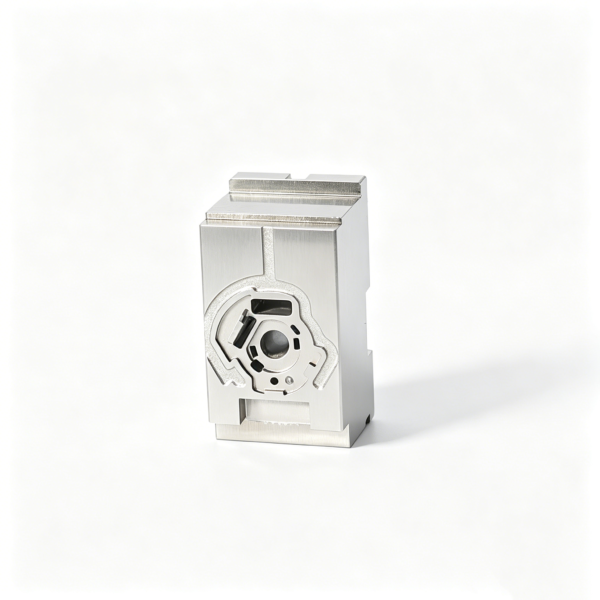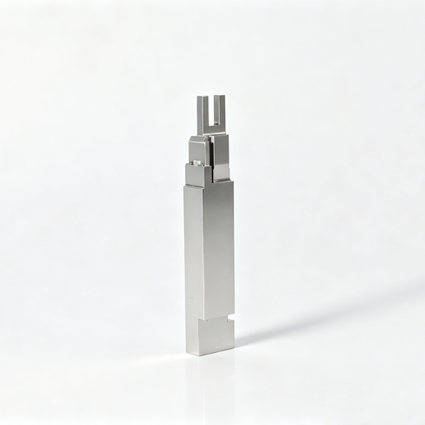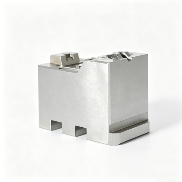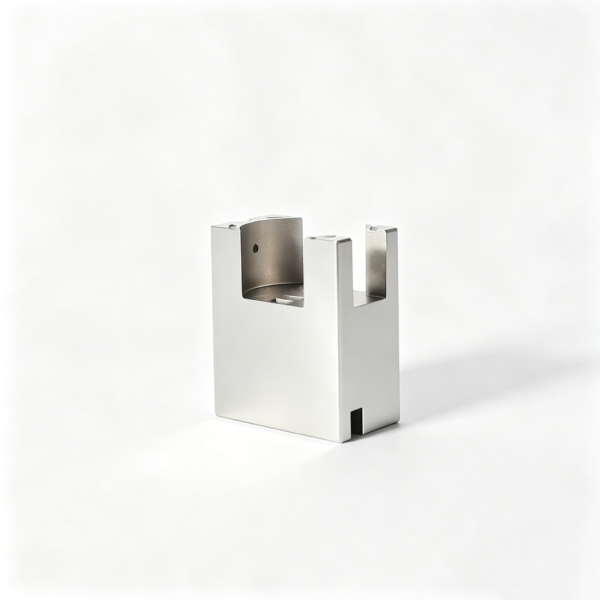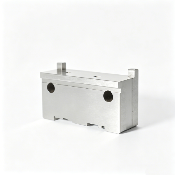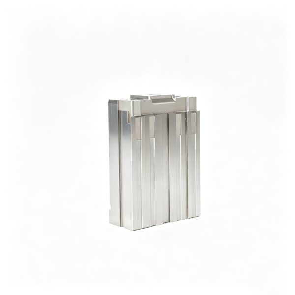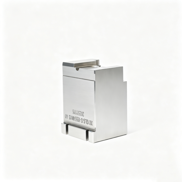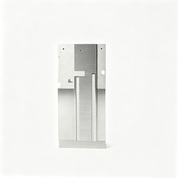
A mold insert surface-finish specification must describe the intended functional surface, the finishing method and the inspection agreement in terms that design, tooling and molding teams interpret the same way. A vague note such as “polish,” “matte” or “SPI finish” can leave direction, location, cutoff, gloss, texture replication and repair acceptance unresolved. The result may be visually inconsistent parts even when the toolmaker believes the drawing was followed.
Use the workflow with the XUXIANG quality and certification system to connect drawing control, insert manufacturing, sample approval and future maintenance.

Start from part function
Define why the surface matters. A cosmetic housing may need controlled gloss and uniform texture. A sliding shutoff may need a directional technical finish. An optical or sealing surface requires different controls from a hidden ejector-side area. Texture can influence appearance, release, scratch visibility, coating adhesion and perceived quality.
Map every critical part surface to the responsible mold face. Identify cavity, core, slide, lifter or replaceable insert. If a part feature spans multiple inserts, define how boundaries and texture transitions should appear. A finish callout on the part drawing should be traceable to tooling surfaces and revision records.
Choose a recognized finish language carefully
Industry comparison charts are useful, but a label alone is not a complete acceptance method. The Protolabs overview of injection molding finishes explains common polished, paper and blasted categories. The Fictiv SPI guideline similarly describes reference groupings. Use such systems to establish a shared starting point, then attach the actual approved standard, process and inspection conditions.
Do not convert a visual category into an exact roughness value unless the relationship has been validated for the material and process. Directional machining marks, polishing waviness and texture geometry can produce similar average readings but different appearance.
Put location and boundary on the drawing
Use a surface map or clearly bounded callout. State whether the finish applies to the complete insert face, a named cavity region, a shutoff, an edge break or a transition band. Avoid leaders that could point to either the molded surface or an adjacent tool surface.
For multiple requirements, use identifiers such as F1, F2 and F3 tied to a finish schedule:
| ID | Tool location | Purpose | Finish definition | Inspection |
|---|---|---|---|---|
| F1 | Main cavity cosmetic face | Visible appearance | Approved polished standard | Visual master and instrument where agreed |
| F2 | Sidewall in draw direction | Release control | Directional technical finish | Direction and comparator |
| F3 | Hidden rib region | Non-cosmetic function | Controlled machining finish | Visual and roughness limit if specified |
Include the cutoff between surfaces and define whether a blend line is permitted. On a replaceable insert, state how its edge must match the surrounding cavity.
Specify direction
Direction matters on draw surfaces, slides, sealing interfaces and brushed aesthetics. Mark the required lay relative to tool movement or part orientation. “Vertical” is ambiguous if the insert can be viewed or mounted in more than one orientation. Use an arrow tied to mold-opening, ejection or a drawing datum.
Crossed or circular polishing marks may behave differently from a consistent draw-direction finish. If the finish is functional, explain the intended effect so the toolmaker does not optimize appearance in a way that harms release.
Control preparation before final finishing
Final finish cannot reliably hide incorrect geometry, EDM recast layer, deep cutter marks, pits or weld defects. Define machining allowance and the sequence for grinding, stoning, paper, compound, blasting, etching or other treatment. Require inspection between stages for critical surfaces.
Material grade, heat treatment and hardness influence polishing and texture response. Mixed steel conditions across adjacent inserts can appear different even with the same nominal process. Link the finish record to material certificate and hardness verification; the mold component hardness verification guide provides the companion control.
Weld repair should require approval on critical cosmetic or sealing surfaces. Record filler, heat treatment, affected zone and re-finishing method. A repaired surface can texture or polish differently from the parent steel.
Use physical standards
An approved plaque or first-off molded part is often the clearest visual standard. Label it with resin, color, texture source, tool revision, molding condition and approval date. Protect it from scratching, UV, chemicals and handling. Photographs can support communication but are not reliable color or gloss masters because camera and display processing change appearance.
For texture supplied by an external specialist, record the supplier code, version, depth range if provided, draft recommendation and any agreed repair procedure. Do not assume similarly named textures from different sources are interchangeable.

Define measurement where it adds value
Roughness parameters can help control technical surfaces, but the specification must name the parameter, filter or cutoff approach, measurement direction, instrument, trace length and sampling locations. A bare “Ra” number is incomplete. The Xometry finish overview illustrates how molded appearance choices differ; tool-surface metrology should be agreed for the specific function.
Gloss measurement on molded parts requires defined geometry, instrument angle, color, resin, surface cleanliness and molding condition. Color and gloss can change with packing, temperature, drying and additive lot. Separate tool acceptance from process troubleshooting.
For optical, sealing or precision sliding surfaces, use the applicable engineering standard and calibrated method selected by the responsible engineer. This general guide does not replace application-specific tolerances.
Inspect the tool and molded result
Tool inspection confirms workmanship and location; molded samples confirm replication and appearance in the chosen resin. Both are needed for critical cosmetic surfaces. Review samples under defined lighting, orientation and viewing distance, with an approved master nearby.
Inspect across cavities when the mold is multi-cavity. A consistent process can still reveal cavity-to-cavity differences from steel, polishing, venting or local temperature. Mark samples by cavity and cycle stage.
Check:
- finish coverage and boundary;
- direction and uniformity;
- scratches, pits, drag lines and polishing waves;
- texture interruptions at inserts, gates, ejectors and parting lines;
- gloss and visual match to master;
- release behavior and evidence of scuffing;
- cleanability and maintenance access.
Consider draft and release
Deeper or more aggressive texture can require additional draft. Confirm the texture supplier’s guidance and validate with the actual resin, geometry and molding conditions. Insufficient draft may cause scuffing, whitening, high ejection force or part damage. Do not polish away a texture locally to solve release without an approved engineering change; that creates an uncontrolled appearance patch.
Release agents can mask a tooling problem and contaminate downstream painting or bonding. Record any use during sampling and do not treat agent-assisted parts as equivalent to the intended stable process unless approved.
Manage changes and repairs
Every finish change should identify reason, affected surface, previous state, new state, responsible approval and reinspection plan. Update the drawing, finish map, physical master and maintenance record. Retire obsolete comparators from the work area.
After insert replacement or repair, repeat tool-surface inspection and molded-part comparison. Check adjacent regions and all cavities, not only the repaired location. Apply the broader engineering change control workflow so maintenance does not silently become a design revision.
Diagnose common disagreements
“The code is correct but the appearance is wrong”
Confirm the physical standard, steel condition, process sequence, molding material, color and lighting. A category code may not capture the approved visual target.
Roughness passes but release is poor
Check measurement direction, local geometry, draft, texture depth, process conditions and scuff evidence. An averaged reading may miss directional or local problems.
Adjacent inserts do not match
Review material, hardness, repair history, polishing operator, process stage and boundary blending. Do not overwork one insert without controlling the other.
Texture looks different by color
Resin color, additives and gloss perception can change appearance. Approve the intended production material and colorways under common conditions.
Approval record
The final record should contain part and tool revision, surface map, finish schedule, direction arrows, physical master ID, material and hardness, process route, tool inspection, molded sample conditions, cavity comparison, deviations and signatures. For critical surfaces, include maintenance and repair limits.
Frequently asked questions
Is an SPI label enough on a drawing?
It is a useful shared reference but may not define location, direction, boundary, master, process or inspection. Add those controls where the surface is important.
Should finish be inspected only on the mold?
No. The molded part shows replication in the actual resin and process. Critical appearance normally requires both tool and part evidence.
Can a photograph serve as the master?
It can document location, but lighting and display variation make it a weak finish or gloss master. Preserve a controlled physical reference.
Does a roughness value define texture appearance?
Not completely. Direction, spacing, waviness and geometry influence appearance and function beyond one average parameter.
Preserve the Approved Surface Through Maintenance
The acceptance record should remain available after tool launch. Cleaning, weld repair, stone work and repolishing can change texture depth, direction, gloss and local draft behavior. Maintenance instructions should identify protected cosmetic zones, permitted tools and the point at which a repaired insert needs renewed surface approval.
After a repair, inspect both the insert and molded evidence using the original method and reference standard. Record the repaired area, technician, process, inspection result and new photographs. If the appearance cannot be restored locally without a visible boundary, engineering and the customer should decide whether to refinish a wider zone or replace the insert. This lifecycle control prevents a qualified surface from gradually drifting through undocumented touch-ups.
Final decision
Approve a mold insert surface finish only when the drawing identifies exact location and direction, the manufacturing route is compatible with material and hardness, a controlled master exists, and tool plus molded-part inspections pass. Link replacements and repairs to change control. This turns an aesthetic adjective into a repeatable engineering requirement.